This document provides instructions to disassemble the transfer gears of a 631G wheel tractor scraper. The steps include:
1. Removing identification marks from components
2. Removing bearing cages, shims, and gears from the transfer gear case using tools
3. Removing bearing cups using pullers and by turning the gear case over
4. Separating additional bearing cages, gears, and bearings from the gear case and each other using bolts and pullers
The disassembly fully removes and separates all components of the transfer gears.
This document provides instructions for disassembling and assembling the transfer gears of a 631G wheel tractor. The disassembly process involves removing 18 components from the transfer gear case including bearing cages, gears, shims, and cups. The assembly process reverses this, cleaning and lubricating parts before installing components in the reverse order, using various tools to position and set bearings. Proper cleaning is emphasized to prevent contamination of hydraulic systems.
The document provides instructions for disassembling and assembling the transfer gears of a 631G wheel tractor. It describes removing 18 components including bearing cages, gears, cups, and seals. It then describes assembling the components in reverse order, including cleaning, lubricating, heating/cooling parts, and adjusting shims to achieve proper end play. Tools required include link brackets, pullers, drivers, and dial indicators.
Caterpillar Cat CP-433E Vibratory Compactor (Prefix BTY) Service Repair Manua...fjkskkedmm4r
This document provides instructions for disassembling and assembling the piston motor (axle propel) of a CP-433E vibratory compactor. The disassembly procedure involves removing 21 components from the housing in a specific order, taking care with spring-loaded parts. The assembly procedure reverses this process in 23 steps, ensuring proper installation of seals, bearings, pins and other components back into their original positions in the housing. Special tools and torque specifications are listed to correctly perform the work.
Caterpillar Cat CS-423E Vibratory Compactor (Prefix CFX) Service Repair Manua...fjkskkedmm4r
This document provides assembly instructions for the axle on a CS-423E vibratory compactor. It details 33 steps to assemble components such as the differential, wheel hubs, brakes, and gearbox. Tools and torque specifications are listed. Parts are cleaned and seals/bearings replaced if damaged before assembly. Components like the differential, wheel hubs, brakes, and gearbox are assembled separately then installed on the axle housing.
Caterpillar Cat CS-433E Vibratory Compactor (Prefix BTY) Service Repair Manua...fjkskkedmm4r
This document provides instructions for disassembling and assembling the piston motor (axle propel) of a CP-433E vibratory compactor. The disassembly procedure involves removing 21 components from the housing in a specific order, taking care with spring-loaded parts. The assembly procedure reverses this process in 23 steps, ensuring proper installation of seals, bearings, pins and other components back into their original positions in the housing. Special tools and torque specifications are listed to correctly perform the work.
Volvo EC55-2 Compact Excavator Parts Catalogue Manual – SN 5001 - 7620.pdffjkskkedmm4r
This document contains specifications for various engine parts for a Volvo EC55-2 engine. It includes sections for the engine, cylinder head, valves, pistons, connecting rods, camshaft, and other components. Each section lists the relevant part numbers, descriptions, quantities, and other details. The document provides an extensive catalogue of replacement parts for this engine model.
JCB 300T TRACKED Robot Parts Catalogue Manual (Serial Number 02427501-024278...fjkskkedmm4r
This document contains parts catalogs and diagrams for hydraulic components for an agricultural construction vehicle. It includes lists of parts with descriptions and quantities for hydraulic circuits, pumps, motors, tubing, valves, filters and other components. Pictures and diagrams show the layout and connections between various hydraulic system parts.
JCB 4CX444 (Sideshift AA AB Engine) BACKOHE LOADER Parts Catalogue Manual (Se...fjkskkedmm4r
This document contains parts listings and diagrams for engine components of a backhoe loader, including:
1. The block assembly diagram lists parts such as the cylinder block, liners, plugs, bolts, and rear seal housing.
2. The crankshaft assembly diagram lists the crankshaft, bearing kits, thrust washers, connecting rod assemblies, pistons, rings, and gears.
3. The document provides additional diagrams for components like the timing case, flywheel, and engine mountings. The parts are identified by part number, description, and quantity for various engine builds.
1) The document provides instructions to disassemble and assemble the final drive of a D9R track-type tractor.
2) It describes using various tools to remove over 30 components of the final drive including gears, shafts, seals, and hubs.
3) Precautions are included when using hydraulic cylinders and heated components to disassemble pieces.
1. The document provides instructions for removing and installing various engine components of a 3406C diesel engine, including the spacer plate, valves, valve seat inserts, bridge dowels, valve guides, oil pan and plate, oil pump, and piston cooling tubes.
2. The instructions describe cleaning and preparing surfaces, using specific tools to remove and install components, and ensuring proper installation and operation after reassembly.
3. The overall process involves removing engine components, cleaning surfaces, installing new parts as needed, and reassembling the engine, with the goal of properly servicing the 3406C diesel engine.
The document provides instructions for disassembling and assembling a recoil cylinder. Key steps include:
1. Removing the recoil cylinder and various components like bolts, guards, valves, and seals.
2. Inspecting parts and cleaning components as needed.
3. Reassembling the recoil cylinder by reinstalling components in reverse order and applying lubricants and seals. Precise torques are specified.
4. The process involves over 20 numbered steps and utilizes various specialized tools to properly disassemble and reassemble the recoil cylinder.
1. Remove the transmission, torque converter, and transfer gears from the tractor. Lift the assembly weighing approximately 1320 kg onto stands.
2. Attach lifting brackets and remove the bolts and nuts securing the 340 kg transfer gears to the transmission. Separate the transfer gears and remove o-rings.
3. Remove the final o-ring seal from the transmission. Install the transfer gears by reversing the removal steps.
This document provides assembly instructions for a final drive on an excavator. It involves assembling and installing several components in the following order: installing bearings and determining shim thickness; installing seals; installing dowel pins; installing the housing on the motor housing; installing coupling gear, bolts, and ring gear; assembling carrier assemblies; installing gears, shafts, and retaining rings; installing the cover and testing for leaks. The process requires precision measurements and uses several specialized tools to properly assemble the final drive.
The document provides instructions for removing and installing the drive shaft group with retarder on a 621E, 623E, or 627E tractor. It describes disconnecting hydraulic lines and removing bolts, covers, and housing to access the drive shaft group. Special care must be taken when removing plates and springs from the retarder, as they are under pressure. The process is reversed for installation, reconnecting hydraulic lines and refastening housings and covers.
This document provides step-by-step instructions to disassemble a piston pump. It begins by removing the piston pump and cleaning it. Key components like the piston assemblies, barrel assembly, springs and seals are then removed. Precision tools are required to remove parts like bearings and seals without damage. The multi-stage process dismantles both sides of the pump housing and internal components like valves, solenoids and control blocks are broken down. Precise part tracking and cleanliness are emphasized for reassembly.
This document provides instructions for disassembling and assembling bevel and transfer gears on a D6M track-type tractor. It outlines 22 steps for disassembly, which include removing brackets, yokes, carriers, cages, seals, bearings, gears, pins, shafts, and other components. It then outlines 21 steps for assembly, which involve cleaning parts, installing bearings, gears, pins, shafts, seals, covers, and other components in the reverse order of disassembly. Proper tools and cleaning procedures are emphasized to prevent damage to components from dirt and contaminants.
The document provides instructions for disassembling and assembling the steering clutch and brake of a D6N track-type tractor. It describes removing the final drive, steering clutch, and brake as separate components. It then details each step to disassemble the steering clutch and brake parts and housing. The corresponding assembly instructions are also provided in reverse order.
The document provides instructions for removing and installing various components of a 3406C diesel engine cylinder head. The procedures include removing and installing the cylinder head assembly, spacer plate, valves, valve seat inserts, bridge dowels, valve guides, and oil pan and plate. The instructions describe the specific steps to disassemble and reassemble each component.
This document provides disassembly and assembly instructions for a 3406C engine governor. It begins with removing the fuel injection pump housing and governor. It then provides 37 detailed steps for disassembling the governor components. The assembly section provides 43 steps for reassembling the governor in reverse order.
This document provides instructions for disassembling and assembling components of the retarder and bearing cage (drive shaft) of a 623G wheel tractor. The disassembly procedure involves using various tools to remove 15 different components. The assembly procedure instructs installing the components in reverse order and refers to other documents for installing related components. Safety notices are provided regarding containing fluids and preventing contamination.
1) The document provides assembly instructions for a final drive on an excavator.
2) It involves over 40 steps to assemble bearings, seals, gears, carriers, housing and cover components.
3) Special tools and procedures are required to set bearing preloads, install seals, and test for leaks. Proper torque values and sealants are specified.
Caterpillar Cat CB-534D VIBRATORY COMPACTOR (Prefix C8M) Service Repair Manua...fjkskkedmm4r
1. The document provides instructions for removing and installing a lifter group from a Caterpillar 3054C engine.
2. It lists the required tools which include a telescoping magnet.
3. The removal procedure involves first removing the camshaft, then using a magnet to remove the lifters from the cylinder block. Installation is the reverse of removal.
The document provides instructions for disassembling and assembling a swivel and swing motor on an excavator. Key steps include:
1. Removing bolts, seals and components to separate the swivel housing, rotor and cover.
2. Applying clean oil before reassembling components and installing seals, retainer and cover.
3. Draining swing motor oil before disconnecting hoses and removing bolts to detach the motor.
4. Dismantling the swing motor involves removing valves, seals, springs and using tools to separate internal components like pistons, plates and barrels.
Caterpillar Cat CB-335E Vibratory Compactor (Prefix C3F) Service Repair Manua...fjkskkedmm4r
This document provides instructions for removing the drum and drum support from a CB-335E vibratory compactor. It involves:
1. Removing the vibratory motor.
2. Disconnecting the water supply hose from the spray bar and removing the scraper and spray bar assembly.
3. Removing the drum support bolts and lifting the drum and drum support from the machine using lifting beams.
Caterpillar Cat CB-334E Vibratory Compactor (Prefix C3F) Service Repair Manua...fjkskkedmm4r
This document provides instructions for removing the drum and drum support from a CB-335E vibratory compactor. It involves:
1. Removing the vibratory motor.
2. Disconnecting the water supply hose from the spray bar and removing the scraper and spray bar assembly.
3. Removing the drum support bolts and lifting the drum and drum support from the machine using lifting beams.
Caterpillar Cat 980G II Wheel Loader (Prefix AXG) Service Repair Manual (AXG0...fjkskkedmm4r
This document provides instructions for removing and installing a valve mechanism cover and valve mechanism cover base on a Caterpillar 3406E engine. The procedure involves:
1. Removing bolts to remove the valve mechanism cover.
2. Cleaning old gasket material and installing a new gasket when reinstalling the cover.
3. Removing bolts and other hardware to remove the valve mechanism cover base. Cleaning and installing new seals when reinstalling.
The instructions provide illustrations and specify torque values for fasteners. Proper cleaning and use of new seals/gaskets is emphasized.
This document provides instructions for removing and installing various components of the front gear group, front housing, valve mechanism cover, and valve mechanism cover base of a Caterpillar 3412E engine used in a 992C wheel loader. The procedures include removing gears, shafts, housings, covers, and electrical harness assemblies. Special tools may be required and components must be kept clean to prevent premature wear. Torques are specified for tightening bolts and nuts.
Understanding Catalytic Converter Theft:
What is a Catalytic Converter?: Learn about the function of catalytic converters in vehicles and why they are targeted by thieves.
Why are They Stolen?: Discover the valuable metals inside catalytic converters (such as platinum, palladium, and rhodium) that make them attractive to criminals.
Steps to Prevent Catalytic Converter Theft:
Parking Strategies: Tips on where and how to park your vehicle to reduce the risk of theft, such as parking in well-lit areas or secure garages.
Protective Devices: Overview of various anti-theft devices available, including catalytic converter locks, shields, and alarms.
Etching and Marking: The benefits of etching your vehicle’s VIN on the catalytic converter or using a catalytic converter marking kit to make it traceable and less appealing to thieves.
Surveillance and Monitoring: Recommendations for using security cameras and motion-sensor lights to deter thieves.
Statistics and Insights:
Theft Rates by Borough: Analysis of data to determine which borough in NYC experiences the highest rate of catalytic converter thefts.
Recent Trends: Current trends and patterns in catalytic converter thefts to help you stay aware of emerging hotspots and tactics used by thieves.
Benefits of This Presentation:
Awareness: Increase your awareness about catalytic converter theft and its impact on vehicle owners.
Practical Tips: Gain actionable insights and tips to effectively prevent catalytic converter theft.
Local Insights: Understand the specific risks in different NYC boroughs, helping you take targeted preventive measures.
This presentation aims to equip you with the knowledge and tools needed to protect your vehicle from catalytic converter theft, ensuring you are prepared and proactive in safeguarding your property.
EV Charging at MFH Properties by Whitaker JamiesonForth
Whitaker Jamieson, Senior Specialist at Forth, gave this presentation at the Forth Addressing The Challenges of Charging at Multi-Family Housing webinar on June 11, 2024.
Top-Quality AC Service for Mini Cooper Optimal Cooling PerformanceMotor Haus
Ensure your Mini Cooper stays cool and comfortable with our top-quality AC service. Our expert technicians provide comprehensive maintenance, repairs, and performance optimization, guaranteeing reliable cooling and peak efficiency. Trust us for quick, professional service that keeps your Mini Cooper's air conditioning system in top condition, ensuring a pleasant driving experience year-round.
Charging Fueling & Infrastructure (CFI) Program Resources by Cat PleinForth
Cat Plein, Development & Communications Director of Forth, gave this presentation at the Forth and Electrification Coalition CFI Grant Program - Overview and Technical Assistance webinar on June 12, 2024.
Real-time driver monitoring is one of the easiest ways to make fleet management efficient as well as seamless. Connected vehicle solutions such as fleet GPS trackers and associated software help businesses in several ways. Refer to the post below for more details.
Dahua provides a comprehensive guide on how to install their security camera systems. Learn about the different types of cameras and system components, as well as the installation process.
Charging and Fueling Infrastructure Grant: Round 2 by Brandt HertensteinForth
Brandt Hertenstein, Program Manager of the Electrification Coalition gave this presentation at the Forth and Electrification Coalition CFI Grant Program - Overview and Technical Assistance webinar on June 12, 2024.
Charging Fueling & Infrastructure (CFI) Program by Kevin MillerForth
Kevin Miller, Senior Advisor, Business Models of the Joint Office of Energy and Transportation gave this presentation at the Forth and Electrification Coalition CFI Grant Program - Overview and Technical Assistance webinar on June 12, 2024.
car rentals in nassau bahamas | atv rental nassau bahamasjustinwilson0857
At Dash Auto Sales & Car Rentals, we take pride in providing top-notch automotive services to residents and visitors alike in Nassau, Bahamas. Whether you're looking to purchase a vehicle, rent a car for your vacation, or embark on an exciting ATV adventure, we have you covered with our wide range of options and exceptional customer service.
Website: www.dashrentacarbah.com
car rentals in nassau bahamas | atv rental nassau bahamas
Caterpillar Cat 631G WHEEL SCRAPER (Prefix DEM) Service Repair Manual (DEM00001 and up).pdf
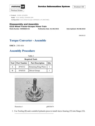
1. Shutdown SIS
Previous Screen
Product: WHEEL SCRAPER
Model: 631G WHEEL SCRAPER DEM
Configuration: 631G Wheel Scraper DEM00001-UP (MACHINE)
Disassembly and Assembly
631G Wheel Tractor-Scraper Power Train
Media Number -RENR8604-01 Publication Date -01/08/2010 Date Updated -09/08/2010
i06636123
Torque Converter - Assemble
SMCS - 3101-016
Assembly Procedure
Table 1
Required Tools
Tool Part Number Part Description Qty
A 2P-8312 Retaining Ring Pliers 1
B 1P-0510 Driver Group 1
Illustration 1 g00528674
1. Use Tooling (B) and a suitable hydraulic press to install sleeve bearing (33) into flange (32).
1/7(W)
w
2021/6/18
https://127.0.0.1/sisweb/sisweb/techdoc/techdoc_print_page.jsp?returnurl=/sisweb/sisw...
2. Illustration 2 g00528612
2. Position flange (32) and install bolts (31) onto housing (9). Tighten bolts (31) to a torque of
120 ± 15 N·m (89 ± 11 lb ft).
Illustration 3 g00525322
3. Install thrust bearing (29) and thrust race (30) into housing (9).
Illustration 4 g00525321
4. Install turbine (23) and clamp ring (28) onto hub (3).
2/7(W)
w
2021/6/18
https://127.0.0.1/sisweb/sisweb/techdoc/techdoc_print_page.jsp?returnurl=/sisweb/sisw...
3. Illustration 5 g00525320
5. Install bolts (27) into turbine (23). Tighten bolts (27) to a torque of 50 ± 7 N·m
(37 ± 5 lb ft). Install thrust race (26) onto hub (3).
Illustration 6 g01102582
6. Install thrust race (25) and thrust bearing (24) onto hub (3).
Illustration 7 g00525315
7. Install turbine (23) and hub (3) as a unit into housing (9).
3/7(W)
w
2021/6/18
https://127.0.0.1/sisweb/sisweb/techdoc/techdoc_print_page.jsp?returnurl=/sisweb/sisw...
4. Illustration 8 g00528953
8. Use Tooling (B) and a suitable press to install sleeve bearing (22) into carrier assembly (12).
Install thrust bearing (21) onto carrier assembly (12).
Illustration 9 g01110492
9. Install side plate (20) to stator (13). Use Tooling (A) to install retaining ring (19) to stator
(13).
Illustration 10 g01102579
10. Use Tooling (B) and a suitable hydraulic press to install freewheel cam (18) into stator (13).
4/7(W)
w
2021/6/18
https://127.0.0.1/sisweb/sisweb/techdoc/techdoc_print_page.jsp?returnurl=/sisweb/sisw...
5. 11. Install stator (13) to carrier assembly (12). Install freewheel springs (16) and freewheel
rollers (17) to freewheel cam (18). Always install new freewheel springs (16) and freewheel
rollers (17). Install freewheel springs (16) with the maximum number of loops in freewheel
springs (16) to the outside of freewheel cam (18). Stator (13) should turn freely in the
clockwise direction. Stator (13) should not turn freely in the counterclockwise direction.
Illustration 11 g01110494
12. Install thrust race (15) to stator (13). Use Tooling (A) to install retaining ring (14) onto
stator (13).
Illustration 12 g00525308
13. Install carrier assembly (12) and stator (13) as a unit into housing (9).
5/7(W)
w
2021/6/18
https://127.0.0.1/sisweb/sisweb/techdoc/techdoc_print_page.jsp?returnurl=/sisweb/sisw...
6. Illustration 13 g01108447
14. Install thrust bearing (11) and seal ring (12A) onto carrier assembly (12).
Illustration 14 g00525305
15. Install impeller hub (8) to impeller (5). Install thrust race (10) onto impeller (5).
Illustration 15 g01102576
16. Install clamp plate (7) and bolts (6) onto impeller hub (8). Tighten bolts (6) to a torque of
50 ± 7 N·m (37 ± 5 lb ft).
17. Install bolts (4) into impeller (5). Tighten bolts (4) to a torque of 50 ± 7 N·m (37 ± 5 lb ft).
6/7(W)
w
2021/6/18
https://127.0.0.1/sisweb/sisweb/techdoc/techdoc_print_page.jsp?returnurl=/sisweb/sisw...
7. Illustration 16 g00525299
18. Use Tooling (B) and a suitable press to install the sleeve bearing in carriage support
assembly (2). Install the sleeve bearing until the sleeve bearing is flush with the outside
machined surface of carriage support assembly (2).
19. Install carriage support assembly (2) onto hub (3). Use Tooling (A) to install retaining ring
(1) onto carriage support assembly (2).
End By:
a. Install the torque converter. Refer to Disassembly and Assembly, "Torque Converter -
Install".
Copyright 1993 - 2021 Caterpillar Inc.
All Rights Reserved.
Private Network For SIS Licensees.
Fri Jun 18 10:24:08 UTC+0800 2021
7/7(W)
w
2021/6/18
https://127.0.0.1/sisweb/sisweb/techdoc/techdoc_print_page.jsp?returnurl=/sisweb/sisw...
8. Shutdown SIS
Previous Screen
Product: WHEEL SCRAPER
Model: 631G WHEEL SCRAPER DEM
Configuration: 631G Wheel Scraper DEM00001-UP (MACHINE)
Disassembly and Assembly
631G Wheel Tractor-Scraper Power Train
Media Number -RENR8604-01 Publication Date -01/08/2010 Date Updated -09/08/2010
i02301155
Transfer Gears - Disassemble
SMCS - 3159-015
Disassembly Procedure
Table 1
Required Tools
Tool Part Number Part Description Qty
A 138-7575 Link Bracket 1
B
8B-7548 Push-Puller Tool Gp 1
8B-7551 Bearing Puller Gp 1
1P-0498 Drive Plate 1
C
5P-4170 Step Plate 1
1P-2321 Combination Puller 1
D
8B-7554 Bearing Cup Puller Gp 1
5P-4170 Step Plate 1
1P-0518 Drive Plate 1
E
8B-7560 Step Plate 1
5F-7345 Screw 1
8B-7554 Bearing Cup Puller Gp 1
F -
Bolts
3/8" - 16 NC by 3 inch
3
Start By:
1/8(W)
w
2021/6/18
https://127.0.0.1/sisweb/sisweb/techdoc/techdoc_print_page.jsp?returnurl=/sisweb/sisw...
9. a. Remove the transfer gear case. Refer to Disassembly and Assembly, "Transfer Gears -
Remove".
b. Remove the transmission oil filter base. Refer to Disassembly and Assembly, "Transmission
Oil Filter Base - Remove and Install".
c. Remove the transmission scavenge pump. Refer to Disassembly and Assembly,
"Transmission Scavenge Pump - Remove".
d. Remove the transmission oil pump. Refer to Disassembly and Assembly, "Transmission Oil
Pump - Remove".
NOTICE
Care must be taken to ensure that fluids are contained during
performance of inspection, maintenance, testing, adjusting, and repair
of the product. Be prepared to collect the fluid with suitable containers
before opening any compartment or disassembling any component
containing fluids.
Refer to Special Publication, NENG2500, "Dealer Service Tool
Catalog" for tools and supplies suitable to collect and contain fluids on
Cat®
products.
Dispose of all fluids according to local regulations and mandates.
NOTICE
Keep all parts clean from contaminants.
Contamination of the hydraulic system with foreign material will
reduce the service life of the hydraulic system components.
To prevent contaminants from entering the hydraulic system, always
plug or cap the lines, fittings, or hoses as they are disconnected. Cover
any disassembled components and clean them properly before
assembly.
Clean the hydraulic system properly after any major component
exchange or especially after a component failure, to remove any
contamination.
1. Put identification marks on components for installation purposes.
2/8(W)
w
2021/6/18
https://127.0.0.1/sisweb/sisweb/techdoc/techdoc_print_page.jsp?returnurl=/sisweb/sisw...
10. Illustration 1 g01048669
2. Remove the bolts that secure bearing cage (1) to the transfer gear case. Use Tooling (F) in
order to separate bearing cage (1) from the transfer gear case.
3. Remove bearing cage (1), shims (2), and pump drive gear (3) from the transfer gear case.
Illustration 2 g01102869
4. Remove the bolts that secure bearing cage (4) to the transfer gear case. Use Tooling (F) in
order to separate bearing cage (4) from the transfer gear case.
5. Remove bearing cage (4), shims (5), and gear (6) from the transfer gear case.
Illustration 3 g00529211
3/8(W)
w
2021/6/18
https://127.0.0.1/sisweb/sisweb/techdoc/techdoc_print_page.jsp?returnurl=/sisweb/sisw...
11. 6. Remove bearing cups (7) and (8) from the transfer gear case. Attach Tooling (A) and a
suitable lifting device onto the transfer gear case. The weight of the transfer gear case is
approximately 340 kg (750 lb). Turn over the transfer gear case. Remove Tooling (A).
Illustration 4 g01102873
7. Remove the bolts that secure bearing cage (9) to the transfer gear case. Use Tooling (F) in
order to separate bearing cage (9) from the transfer gear case.
8. Remove bearing cage (9), shims (10), and gear (11) from the transfer gear case.
Illustration 5 g00529214
9. Remove bearing cup (12) from the transfer gear case. Attach Tooling (A) and a suitable
lifting device onto the transfer gear case. Turn over the transfer gear case.
4/8(W)
w
2021/6/18
https://127.0.0.1/sisweb/sisweb/techdoc/techdoc_print_page.jsp?returnurl=/sisweb/sisw...
12. Illustration 6 g00529215
10. Remove bolts (13) that secure bearing cage (14) to the transfer gear case. If necessary, rotate
the gear until the three threaded holes are visible in bearing cage (14). Install Tooling (F)
through gear (15) and into bearing cage (14). Tighten Tooling (F) evenly until bearing cage
(14) and gear (15) separate from the transfer gear case. Remove bearing cage (14) and gear
(15) as a unit from the transfer gear case.
Illustration 7 g00529216
Illustration 8 g00529257
11. Remove retaining ring (16) from gear (15). Remove bearing (17) and bearing cage (14)
from gear (15).
5/8(W)
w
2021/6/18
https://127.0.0.1/sisweb/sisweb/techdoc/techdoc_print_page.jsp?returnurl=/sisweb/sisw...
13. Illustration 9 g01048544
12. Remove bearing (17) from bearing cage (14).
Illustration 10 g01048548
13. Remove bolts (19) and separate gear (20) from gear (11). Use Tooling (B) to remove
bearing cone (18) from gear (11). Repeat the procedure for the bearing cone on the opposite
side of the gear.
Illustration 11 g01048549
14. Use Tooling (C) to remove bearing cone (21) from gear (6). Repeat the procedure for the
bearing cone on the opposite side of gear (6).
6/8(W)
w
2021/6/18
https://127.0.0.1/sisweb/sisweb/techdoc/techdoc_print_page.jsp?returnurl=/sisweb/sisw...
14. Illustration 12 g01048550
15. Use Tooling (C) to remove bearing cone (22) from gear (3). Repeat the procedure for the
bearing cone on the opposite side of gear (3).
Illustration 13 g01048551
16. Use Tooling (D) to remove bearing cup (23) from bearing cage (4). Remove O-ring seal
(24) from bearing cage (4).
Illustration 14 g01048553
17. Remove bearing cup (25) from bearing cage (9).
7/8(W)
w
2021/6/18
https://127.0.0.1/sisweb/sisweb/techdoc/techdoc_print_page.jsp?returnurl=/sisweb/sisw...
15. Illustration 15 g01048552
18. Use Tooling (E) to remove bearing cup (26) from bearing cage (1). Remove O-ring seal (27)
from bearing cage (1).
Copyright 1993 - 2021 Caterpillar Inc.
All Rights Reserved.
Private Network For SIS Licensees.
Fri Jun 18 10:25:11 UTC+0800 2021
8/8(W)
w
2021/6/18
https://127.0.0.1/sisweb/sisweb/techdoc/techdoc_print_page.jsp?returnurl=/sisweb/sisw...
16. Shutdown SIS
Previous Screen
Product: WHEEL SCRAPER
Model: 631G WHEEL SCRAPER DEM
Configuration: 631G Wheel Scraper DEM00001-UP (MACHINE)
Disassembly and Assembly
631G Wheel Tractor-Scraper Power Train
Media Number -RENR8604-01 Publication Date -01/08/2010 Date Updated -09/08/2010
i07232119
Transfer Gears - Assemble
SMCS - 3159-016
Assembly Procedure
Table 1
Required Tools
Tool Part Number Part Description Qty
A 138-7575 Link Bracket 1
G 1P-0510 Driver Group 1
H 8T-5096 Dial Indicator 1
NOTICE
Keep all parts clean from contaminants.
Contamination of the hydraulic system with foreign material will
reduce the service life of the hydraulic system components.
To prevent contaminants from entering the hydraulic system, always
plug or cap the lines, fittings, or hoses as they are disconnected. Cover
any disassembled components and clean them properly before
assembly.
Clean the hydraulic system properly after any major component
exchange or especially after a component failure, to remove any
contamination.
1/9(W)
w
2021/6/18
https://127.0.0.1/sisweb/sisweb/techdoc/techdoc_print_page.jsp?returnurl=/sisweb/sisw...
17. 1. Clean all parts and inspect all parts. If any parts are worn or damaged, use new parts for
replacement.
2. Lubricate O-ring seals with the lubricant that is being sealed.
Illustration 1 g01048544
3. Install bearing (17) into bearing cage (14).
Illustration 2 g00529216
4. Use Tooling (G) to install bearing (17) and bearing cage (14) to gear (15). Install bearing
(17) and bearing cage (14) until the retaining ring groove is visible. Install retaining ring
(16) to gear (15).
2/9(W)
w
2021/6/18
https://127.0.0.1/sisweb/sisweb/techdoc/techdoc_print_page.jsp?returnurl=/sisweb/sisw...
18. Illustration 3 g00529215
5. Position gear (15) and bearing cage (14) in the transfer gear case. Install bolts (13) that
secure bearing cage (14) to the transfer gear case. Tighten bolts (13) to a torque of
55 ± 10 N·m (41 ± 7 lb ft).
Illustration 4 g01048552
6. Install O-ring seal (27) onto bearing cage (1). Lower the temperature of bearing cup (26).
Install bearing cup (26) to bearing cage (1). Check that bearing cup (26) is seated in the bore
of bearing cage (1).
Illustration 5 g01048553
7. Lower the temperature of bearing cup (25). Install bearing cup (25) to bearing cage (9).
Check that bearing cup (25) is seated in the bore of bearing cage (9).
3/9(W)
w
2021/6/18
https://127.0.0.1/sisweb/sisweb/techdoc/techdoc_print_page.jsp?returnurl=/sisweb/sisw...
19. Illustration 6 g01048551
8. Install O-ring seal (24) to bearing cage (4). Lower the temperature of bearing cup (23).
Install bearing cup (23) to bearing cage (4). Check that bearing cup (23) is seated in the bore
of bearing cage (4).
Illustration 7 g01048550
9. Raise the temperature of bearing cone (22). Install bearing cone (22) on gear (3). Repeat the
procedure for the bearing cone on the opposite side of gear (3).
Illustration 8 g01048549
4/9(W)
w
2021/6/18
https://127.0.0.1/sisweb/sisweb/techdoc/techdoc_print_page.jsp?returnurl=/sisweb/sisw...
20. 10. Raise the temperature of bearing cone (21). Install bearing cone (21) on gear (6). Repeat the
procedure for the bearing cone on the opposite side of gear (6).
Illustration 9 g01048548
11. Raise the temperature of bearing cone (18). Install bearing cone (18) on gear (11). Repeat
the procedure for the bearing cone on the opposite side of gear (11).
12. Position gear (20) on gear (11). Install bolts (19). Tighten bolts (19) to a torque of
55 ± 10 N·m (41 ± 7 lb ft). Attach Tooling (A) and a suitable lifting device onto the transfer
gear case. The weight of the transfer gear case is approximately 340 kg (750 lb). Turn over
the transfer gear case. Remove Tooling (A).
Illustration 10 g00529214
13. Lower the temperature of bearing cup (12). Use Tooling (G) to install bearing cup (12) to
the transfer gear case. Check that bearing cup (12) is seated in the bore of the transfer gear
case.
5/9(W)
w
2021/6/18
https://127.0.0.1/sisweb/sisweb/techdoc/techdoc_print_page.jsp?returnurl=/sisweb/sisw...
21. Illustration 11 g00529695
Illustration 12 g01048735
14. Position gear (11) in the transfer gear case. Install bearing cage (9) and shims (10). Install
bolts (28) that hold bearing cage (9) in position. Tighten bolts (28) to a torque of
55 ± 10 N·m (41 ± 7 lb ft).
15. Position Tooling (H) in the transfer gear case, as shown. Make sure that the dial indicator is
in contact with gear (11). Use a pry bar to move gear (11) up and down. Adjust shims (10)
to obtain an end play of 0.15 ± 0.05 mm (0.006 ± 0.002 inch). Tighten bolts (28) to a torque
of 55 ± 10 N·m (41 ± 7 lb ft).
Illustration 13 g00529211
6/9(W)
w
2021/6/18
https://127.0.0.1/sisweb/sisweb/techdoc/techdoc_print_page.jsp?returnurl=/sisweb/sisw...
22. 16. Use Tooling (G) to install bearing cups (7) and (8) to the transfer gear case. Check that
bearing cups (7) and (8) is seated in the bore of the transfer gear case.
Illustration 14 g00529696
Illustration 15 g01048736
17. Position gear (6) in the transfer gear case with the internal snap ring groove facing up.
Install bearing cage (4) and shims (5). Install the bolts (29) that hold bearing cage (4) in
position. Tighten bolts (29) to a torque of 55 ± 10 N·m (41 ± 7 lb ft).
18. Attach Tooling (A) and a suitable lifting device to the transfer gear case. Place the transfer
gear case on wood blocks, as shown. Position Tooling (H) on the transfer gear case, as
shown. Make sure that the dial indicator is in contact with gear (6). Use a pry bar to move
gear (6) up and down. Adjust shims (5) to obtain an end play of 0.15 ± 0.05 mm
(0.006 ± 0.002 inch). Tighten bolts (29) to a torque of 55 ± 10 N·m (41 ± 7 lb ft).
7/9(W)
w
2021/6/18
https://127.0.0.1/sisweb/sisweb/techdoc/techdoc_print_page.jsp?returnurl=/sisweb/sisw...
23. Illustration 16 g00529697
Illustration 17 g01048737
19. Position gear (3) in the transfer gear case. Install bearing cage (1) and shims (2). Install the
bolts (30) that hold bearing cage (1) in position. Tighten bolts (30) to a torque of
55 ± 10 N·m (41 ± 7 lb ft).
20. Position Tooling (H) on the transfer gear case, as shown. Make sure that the dial indicator is
in contact with gear (3). Use a pry bar to move gear (3) up and down. Adjust shims (2) to
obtain an end play of 0.15 ± 0.05 mm (0.006 ± 0.002 inch). Tighten bolts (30) to a torque of
55 ± 10 N·m (41 ± 7 lb ft).
End By:
a. Install the transmission oil pump. Refer to Disassembly and Assembly, "Transmission Oil
Pump - Install".
b. Install the transmission scavenge pump. Refer to Disassembly and Assembly, "Transmission
Scavenge Pump - Install".
c. Install the transmission oil filter base. Refer to Disassembly and Assembly, "Transmission
Oil Filter Base - Remove and Install".
d. Install the transfer gear case. Refer to Disassembly and Assembly, "Transfer Gears -
Install".
8/9(W)
w
2021/6/18
https://127.0.0.1/sisweb/sisweb/techdoc/techdoc_print_page.jsp?returnurl=/sisweb/sisw...
24. Please write to us.
Our email:
aservicemanualpdf@yahoo.com
Please go to the homepage
to get the full manual, or
other brand PDF manuals.
Home Site:
aservicemanualpdf.com
25. Thank you very much for
your reading. Please Click
Here. Then Get COMPLETE
MANUAL. NO WAITING
NOTE:
If there is no response to
click on the link above,
please download the PDF
document first and then
click on it.
GET MORE OTHER MANUALS https://www.aservicemanualpdf.com/
26. Copyright 1993 - 2021 Caterpillar Inc.
All Rights Reserved.
Private Network For SIS Licensees.
Fri Jun 18 10:26:14 UTC+0800 2021
9/9(W)
w
2021/6/18
https://127.0.0.1/sisweb/sisweb/techdoc/techdoc_print_page.jsp?returnurl=/sisweb/sisw...
27. Shutdown SIS
Previous Screen
Product: WHEEL SCRAPER
Model: 631G WHEEL SCRAPER DEM
Configuration: 631G Wheel Scraper DEM00001-UP (MACHINE)
Disassembly and Assembly
631G Wheel Tractor-Scraper Power Train
Media Number -RENR8604-01 Publication Date -01/08/2010 Date Updated -09/08/2010
i02568748
Transmission Planetary - Disassemble
SMCS - 3030-015
Disassembly Procedure
Table 1
Required Tools
Tool Part Number Part Description Qty
A 1P-2420 Transmission Repair Stand 1
B FT-0833 Clamp 2
C 2P-8312 Retaining Ring Pliers 1
D FT-1335 Transmission Fixture 1
E 1P-0520 Driver Group 1
F 138-7575 Link Bracket 2
G 138-7573 Link Bracket 2
H -
Forcing Bolt
3/8 - 16 NC by 3 inch
2
Start By:
A. Separate the transfer gears from the transmission. Refer to Disassembly and Assembly ,
"Torque Converter, Transmission and Transfer Gear - Separate".
B. Remove the transmission hydraulic control valve. Refer to Disassembly and Assembly ,
"Transmission Hydraulic Control Valve - Remove".
NOTICE
1/36(W)
w
2021/6/18
https://127.0.0.1/sisweb/sisweb/techdoc/techdoc_print_page.jsp?returnurl=/sisweb/sisw...
28. Care must be taken to ensure that fluids are contained during
performance of inspection, maintenance, testing, adjusting and repair
of the product. Be prepared to collect the fluid with suitable containers
before opening any compartment or disassembling any component
containing fluids.
Refer to Special Publication, NENG2500, "Caterpillar Dealer Service
Tool Catalog" for tools and supplies suitable to collect and contain
fluids on Caterpillar products.
Dispose of all fluids according to local regulations and mandates.
Illustration 1 g01013127
1. Install Tooling (F) and a suitable lifting device onto transmission assembly (1) . Position
transmission assembly (1) onto Tooling (A) . The transmission assembly weighs
approximately 703 kg (1550 lb).
Illustration 2 g01013128
2/36(W)
w
2021/6/18
https://127.0.0.1/sisweb/sisweb/techdoc/techdoc_print_page.jsp?returnurl=/sisweb/sisw...