This document provides instructions for disassembling and assembling various components of a 120 Motor Grader's sleeve metering fuel system, including:
1. Removing and installing a speed limiter on the fuel system governor.
2. Separating and reconnecting the governor from the fuel injection pump housing.
3. Disassembling and reassembling the governor.
4. Removing and installing the fuel check valve and bypass valve.
5. An overview of fuel injection pumps and housings.
The document contains detailed step-by-step instructions and notes for working with each component to ensure proper disassembly and reassembly. References are made to other documents for testing, adjusting and
Comprehensive program for Agricultural Finance, the Automotive Sector, and Empowerment . We will define the full scope and provide a detailed two-week plan for identifying strategic partners in each area within Limpopo, including target areas.:
1. Agricultural : Supporting Primary and Secondary Agriculture
• Scope: Provide support solutions to enhance agricultural productivity and sustainability.
• Target Areas: Polokwane, Tzaneen, Thohoyandou, Makhado, and Giyani.
2. Automotive Sector: Partnerships with Mechanics and Panel Beater Shops
• Scope: Develop collaborations with automotive service providers to improve service quality and business operations.
• Target Areas: Polokwane, Lephalale, Mokopane, Phalaborwa, and Bela-Bela.
3. Empowerment : Focusing on Women Empowerment
• Scope: Provide business support support and training to women-owned businesses, promoting economic inclusion.
• Target Areas: Polokwane, Thohoyandou, Musina, Burgersfort, and Louis Trichardt.
We will also prioritize Industrial Economic Zone areas and their priorities.
Sign up on https://profilesmes.online/welcome/
To be eligible:
1. You must have a registered business and operate in Limpopo
2. Generate revenue
3. Sectors : Agriculture ( primary and secondary) and Automative
Women and Youth are encouraged to apply even if you don't fall in those sectors.
𝘼𝙣𝙩𝙞𝙦𝙪𝙚 𝙋𝙡𝙖𝙨𝙩𝙞𝙘 𝙏𝙧𝙖𝙙𝙚𝙧𝙨 𝙞𝙨 𝙫𝙚𝙧𝙮 𝙛𝙖𝙢𝙤𝙪𝙨 𝙛𝙤𝙧 𝙢𝙖𝙣𝙪𝙛𝙖𝙘𝙩𝙪𝙧𝙞𝙣𝙜 𝙩𝙝𝙚𝙞𝙧 𝙥𝙧𝙤𝙙𝙪𝙘𝙩𝙨. 𝙒𝙚 𝙝𝙖𝙫𝙚 𝙖𝙡𝙡 𝙩𝙝𝙚 𝙥𝙡𝙖𝙨𝙩𝙞𝙘 𝙜𝙧𝙖𝙣𝙪𝙡𝙚𝙨 𝙪𝙨𝙚𝙙 𝙞𝙣 𝙖𝙪𝙩𝙤𝙢𝙤𝙩𝙞𝙫𝙚 𝙖𝙣𝙙 𝙖𝙪𝙩𝙤 𝙥𝙖𝙧𝙩𝙨 𝙖𝙣𝙙 𝙖𝙡𝙡 𝙩𝙝𝙚 𝙛𝙖𝙢𝙤𝙪𝙨 𝙘𝙤𝙢𝙥𝙖𝙣𝙞𝙚𝙨 𝙗𝙪𝙮 𝙩𝙝𝙚 𝙜𝙧𝙖𝙣𝙪𝙡𝙚𝙨 𝙛𝙧𝙤𝙢 𝙪𝙨.
Over the 10 years, we have gained a strong foothold in the market due to our range's high quality, competitive prices, and time-lined delivery schedules.
Things to remember while upgrading the brakes of your carjennifermiller8137
Upgrading the brakes of your car? Keep these things in mind before doing so. Additionally, start using an OBD 2 GPS tracker so that you never miss a vehicle maintenance appointment. On top of this, a car GPS tracker will also let you master good driving habits that will let you increase the operational life of your car’s brakes.
What Exactly Is The Common Rail Direct Injection System & How Does It WorkMotor Cars International
Learn about Common Rail Direct Injection (CRDi) - the revolutionary technology that has made diesel engines more efficient. Explore its workings, advantages like enhanced fuel efficiency and increased power output, along with drawbacks such as complexity and higher initial cost. Compare CRDi with traditional diesel engines and discover why it's the preferred choice for modern engines.
Why Is Your BMW X3 Hood Not Responding To Release CommandsDart Auto
Experiencing difficulty opening your BMW X3's hood? This guide explores potential issues like mechanical obstruction, hood release mechanism failure, electrical problems, and emergency release malfunctions. Troubleshooting tips include basic checks, clearing obstructions, applying pressure, and using the emergency release.
Symptoms like intermittent starting and key recognition errors signal potential problems with your Mercedes’ EIS. Use diagnostic steps like error code checks and spare key tests. Professional diagnosis and solutions like EIS replacement ensure safe driving. Consult a qualified technician for accurate diagnosis and repair.
"Trans Failsafe Prog" on your BMW X5 indicates potential transmission issues requiring immediate action. This safety feature activates in response to abnormalities like low fluid levels, leaks, faulty sensors, electrical or mechanical failures, and overheating.
5 Warning Signs Your BMW's Intelligent Battery Sensor Needs AttentionBertini's German Motors
IBS monitors and manages your BMW’s battery performance. If it malfunctions, you will have to deal with an array of electrical issues in your vehicle. Recognize warning signs like dimming headlights, frequent battery replacements, and electrical malfunctions to address potential IBS issues promptly.
Core technology of Hyundai Motor Group's EV platform 'E-GMP'Hyundai Motor Group
What’s the force behind Hyundai Motor Group's EV performance and quality?
Maximized driving performance and quick charging time through high-density battery pack and fast charging technology and applicable to various vehicle types!
Discover more about Hyundai Motor Group’s EV platform ‘E-GMP’!
What Does the PARKTRONIC Inoperative, See Owner's Manual Message Mean for You...Autohaus Service and Sales
Learn what "PARKTRONIC Inoperative, See Owner's Manual" means for your Mercedes-Benz. This message indicates a malfunction in the parking assistance system, potentially due to sensor issues or electrical faults. Prompt attention is crucial to ensure safety and functionality. Follow steps outlined for diagnosis and repair in the owner's manual.
What Does the Active Steering Malfunction Warning Mean for Your BMWTanner Motors
Discover the reasons why your BMW’s Active Steering malfunction warning might come on. From electrical glitches to mechanical failures and software anomalies, addressing these promptly with professional inspection and maintenance ensures continued safety and performance on the road, maintaining the integrity of your driving experience.
In this presentation, we have discussed a very important feature of BMW X5 cars… the Comfort Access. Things that can significantly limit its functionality. And things that you can try to restore the functionality of such a convenient feature of your vehicle.
Why Isn't Your BMW X5's Comfort Access Functioning Properly Find Out Here
Caterpillar Cat 120 MOTOR GRADER (Prefix 10R) Service Repair Manual Instant Download 1.pdf
1. Product: MOTOR GRADER
Model: 120 MOTOR GRADER 10R
Configuration: 120 MOTOR GRADER 10R02882-UP (MACHINE)
Disassembly and Assembly
SLEEVE METERING FUEL SYSTEM FOR FOUR AND SIX CYLINDER 4.75"
Media Number -REG01400-01 Publication Date -01/03/1974 Date Updated -17/03/2010
REG014000005
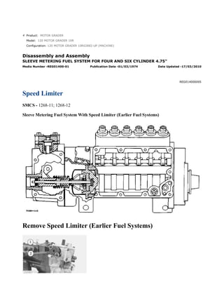
Speed Limiter
SMCS - 1268-11; 1268-12
Sleeve Metering Fuel System With Speed Limiter (Earlier Fuel Systems)
Remove Speed Limiter (Earlier Fuel Systems)
1/2
120 MOTOR GRADER 10R02882-UP (MACHINE)(UEG0726S - 00) - Documentation
2021/6/21
https://127.0.0.1/sisweb/sisweb/techdoc/techdoc_print_page.jsp?returnurl=/sis...
2. 1. Remove the bolts (1) and washers that hold the cover (2) to governor housing. Remove the cover
(2).
2. Remove the diaphragm from governor housing.
3. Remove the plunger (4) and spring (3) from governor housing.
4. Remove the body (5) from the governor housing.
Install Speed Limiter (Earlier Fuel Systems)
1. Install the body, spring, and plunger (1).
2. Install the diaphragm (2) and cover.
3. Install the bolts (3) and washers.
4. See ADJUSTMENT of SPEED LIMITER in TESTING AND ADJUSTING.
2/2
120 MOTOR GRADER 10R02882-UP (MACHINE)(UEG0726S - 00) - Documentation
2021/6/21
https://127.0.0.1/sisweb/sisweb/techdoc/techdoc_print_page.jsp?returnurl=/sis...
3. Product: MOTOR GRADER
Model: 120 MOTOR GRADER 10R
Configuration: 120 MOTOR GRADER 10R02882-UP (MACHINE)
Disassembly and Assembly
SLEEVE METERING FUEL SYSTEM FOR FOUR AND SIX CYLINDER 4.75"
Media Number -REG01400-01 Publication Date -01/03/1974 Date Updated -17/03/2010
REG014000006
Fuel Injection Pump Housing And Governor
SMCS - 1268-11; 1268-12
Separation Of Governor From Fuel Injection Pump Housing
1. Put the fuel injection pump housing on tool (A).
2. Remove bolts (1) that hold the governor housing (2) to the fuel injection pump housing.
1/6
120 MOTOR GRADER 10R02882-UP (MACHINE)(UEG0726S - 00) - Documentation
2021/6/21
https://127.0.0.1/sisweb/sisweb/techdoc/techdoc_print_page.jsp?returnurl=/sis...
4. 3. Remove governor housing (2) from pump housing.
4. Remove cover (5) over the torque spring.
5. Remove spring (8), (wave) washer (7) and guide (6) from governor housing.
6. Remove seat (3) and over fueling spring (4).
7. Pull shaft (9) up and remove shaft and lever from the housing.
8. Remove torque spring assembly (10) and pin.
NOTE: Some fuel systems do not have a torque spring. They have only a stop.
9. Remove riser (follower) (11) from the shaft.
10. Remove ring and lever (12) from the dowel.
11. Remove cover (13) for the flyweights with tool (B).
NOTE: Tool (B) can cause damage to the cover. Always inspect cover and install a new cover if
needed.
2/6
120 MOTOR GRADER 10R02882-UP (MACHINE)(UEG0726S - 00) - Documentation
2021/6/21
https://127.0.0.1/sisweb/sisweb/techdoc/techdoc_print_page.jsp?returnurl=/sis...
5. 12. Install timing pin (14) to hold the camshaft from turning.
13. Remove bolts (15) that hold flyweight assembly to camshaft.
14. Remove the flyweight assembly (16) from the fuel injection pump housing.
15. Remove the timing pin from the housing.
Connection Of Governor To Fuel Injection Pump Housing
1. Put the fuel injection pump housing on tool (A).
2. Install timing pin (1) to keep the camshaft from turning.
3. Put flyweight assembly (2) in position on the camshaft.
3/6
120 MOTOR GRADER 10R02882-UP (MACHINE)(UEG0726S - 00) - Documentation
2021/6/21
https://127.0.0.1/sisweb/sisweb/techdoc/techdoc_print_page.jsp?returnurl=/sis...
6. NOTICE
Be sure pin (3) that holds shaft is in the correct position on back of the
flyweight assembly.
4. Install new bolts for the flyweight assembly.
NOTE: The bolts for the flyweight assembly have a locking material on the threads and must not
be used more than one time.
5. Install cover over the flyweight assembly with tool (B).
6. Grind a taper on the bottom edge of a 1/8" screwdriver (4). Install the screwdriver through the
bolt hole in the governor housing. The screwdriver must fit evenly against the flyweight assembly
cover. Make a mark (stake) in four places around the cover in line with the groove in the camshaft.
NOTICE
Never install a used flyweight cover that is bent.
4/6
120 MOTOR GRADER 10R02882-UP (MACHINE)(UEG0726S - 00) - Documentation
2021/6/21
https://127.0.0.1/sisweb/sisweb/techdoc/techdoc_print_page.jsp?returnurl=/sis...
7. 7. Install lever (5) on the dowel. Install ring (6) that holds lever on dowel.
8. Install pin (7) in the housing with the round end down.
9. Put riser (follower) (10) in position between the flyweights. Lift the flyweight up with a piece
of wire and push riser (follower) forward.
10. Put lever (9) into position in groove of riser (follower) (10) and ball end engaged in the sleeve
shaft lever (8). Install shaft to hold lever in place.
NOTICE
If lever (9) is not installed correctly, the governor cannot operate and
can cause the engine to over speed.
5/6
120 MOTOR GRADER 10R02882-UP (MACHINE)(UEG0726S - 00) - Documentation
2021/6/21
https://127.0.0.1/sisweb/sisweb/techdoc/techdoc_print_page.jsp?returnurl=/sis...
8. 11. Install over fueling spring (13) and seat (12) on shaft.
12. Install stud (14) and torque spring or stop bar (11) on the housing.
NOTICE
The screw that holds the torque spring must not go beyond the inner
surface of the governor housing.
13. Install cover (15) over torque spring after adjustment has been made.
14. Install guide, (wave) washer and spring (16) in the governor housing.
15. Put the governor housing on the fuel injection pump housing and install the bolts.
end by:
a) make adjustment of fuel system setting (See Fuel System Setting in Testing and Adjusting)
6/6
120 MOTOR GRADER 10R02882-UP (MACHINE)(UEG0726S - 00) - Documentation
2021/6/21
https://127.0.0.1/sisweb/sisweb/techdoc/techdoc_print_page.jsp?returnurl=/sis...
9. Product: MOTOR GRADER
Model: 120 MOTOR GRADER 10R
Configuration: 120 MOTOR GRADER 10R02882-UP (MACHINE)
Disassembly and Assembly
SLEEVE METERING FUEL SYSTEM FOR FOUR AND SIX CYLINDER 4.75"
Media Number -REG01400-01 Publication Date -01/03/1974 Date Updated -17/03/2010
REG014000007
Governor
SMCS - 1264-15; 1264-16
Disassemble Governor
start by:
a) separation of governor from fuel injection pump housing
1. Remove shaft (2). Remove pin (1) from shaft.
2. Remove pins (3) from the flyweights. Remove flyweights (4).
3. Remove ring, races (6) and bearing from the riser (follower) (5).
1/6
120 MOTOR GRADER 10R02882-UP (MACHINE)(UEG0726S - 00) - Documentation
2021/6/21
https://127.0.0.1/sisweb/sisweb/techdoc/techdoc_print_page.jsp?returnurl=/sis...
10. 4. Remove cover (7) and spring (8) from governor housing.
NOTE: There is force on the cover from the spring.
5. Remove seal (9) from cover.
6. Remove cover (10) for the low and high idle adjustment.
7. Remove locknut and screw (13) for the high idle adjustment.
8. Remove bolt (15) and washers for the low idle adjustment.
9. Remove spring (16) and guide.
10. Remove pin (14) and plate (11).
11. Remove shaft (12) from the housing.
12. Remove pin (18) and two spacers (17) from shaft.
NOTE: Earlier fuel systems have a ball in place of spacers (17) and pin (18).
2/6
120 MOTOR GRADER 10R02882-UP (MACHINE)(UEG0726S - 00) - Documentation
2021/6/21
https://127.0.0.1/sisweb/sisweb/techdoc/techdoc_print_page.jsp?returnurl=/sis...
11. 13. Remove shaft (19) from the governor housing.
14. Remove washer (20) and levers (21) and (22) from governor housing.
15. Remove cover (23) from governor housing.
16. Remove seal (25) and bearing.
17. Remove seals (24) and (26) from governor housing.
Assemble Governor
3/6
120 MOTOR GRADER 10R02882-UP (MACHINE)(UEG0726S - 00) - Documentation
2021/6/21
https://127.0.0.1/sisweb/sisweb/techdoc/techdoc_print_page.jsp?returnurl=/sis...
12. 1. Install bearing and seal in the housing with tool (A). The lip of the seal must be toward the
bearing.
2. Install seal (1) in housing with tool (A). The lip of seal must be toward inside of housing.
3. Install seal (2) in housing with tooling (B). The lip of seal must be toward the inside of housing.
4. Install shaft (3) in the housing.
5. Install plates (4), spacers (8) and pin (7) on shaft.
6. Install shaft (5) in housing and through washer (9) and levers (6).
7. Install pin (11) in holes of the plates.
8. Install screw (10) and locknut for high idle adjustment.
4/6
120 MOTOR GRADER 10R02882-UP (MACHINE)(UEG0726S - 00) - Documentation
2021/6/21
https://127.0.0.1/sisweb/sisweb/techdoc/techdoc_print_page.jsp?returnurl=/sis...
13. 9. Install spring (13) and guide.
10. Install bolts (12) and washer for low idle adjustment.
11. Push plate and pin (11) over toward the bolt (12) and tighten the bolt.
12. Install seal in cover with tooling (B). The lip of seal must be toward the inside.
13. Install spring (15) in the cover. Install cover (14) on housing.
NOTICE
The spring (15) must be installed with the end of spring as shown.
14. Install cover (16) for the idle adjustment screws.
5/6
120 MOTOR GRADER 10R02882-UP (MACHINE)(UEG0726S - 00) - Documentation
2021/6/21
https://127.0.0.1/sisweb/sisweb/techdoc/techdoc_print_page.jsp?returnurl=/sis...
14. 15. Install bearing (19) between the races (18) on riser (follower) (17). Install ring (20) that holds
the washers on the riser (follower).
16. Install pin in shaft (23).
17. Install flyweights (22) and pin (21).
18. Install shaft (23) in the flyweight assembly.
end by:
a) connection of governor to fuel injection pump housing
6/6
120 MOTOR GRADER 10R02882-UP (MACHINE)(UEG0726S - 00) - Documentation
2021/6/21
https://127.0.0.1/sisweb/sisweb/techdoc/techdoc_print_page.jsp?returnurl=/sis...
15. Product: MOTOR GRADER
Model: 120 MOTOR GRADER 10R
Configuration: 120 MOTOR GRADER 10R02882-UP (MACHINE)
Disassembly and Assembly
SLEEVE METERING FUEL SYSTEM FOR FOUR AND SIX CYLINDER 4.75"
Media Number -REG01400-01 Publication Date -01/03/1974 Date Updated -17/03/2010
REG014000008
Fuel Check Valve And Bypass Valve
SMCS - 1264-15; 1264-16
Remove Fuel Check Valve And Bypass Valve
1. Remove fuel from the pump housing and install on tool (A).
2. Remove cover (2) from top cover.
3. Remove fuel inlet and return housing (1) from top cover.
1/4
120 MOTOR GRADER 10R02882-UP (MACHINE)(UEG0726S - 00) - Documentation
2021/6/21
https://127.0.0.1/sisweb/sisweb/techdoc/techdoc_print_page.jsp?returnurl=/sis...
16. 4. Remove elbow (3) and disc (4) from fuel inlet and return housing.
NOTE: The function of the disc (4) is to keep the fuel in the pump housing from returning to the
tank when the engine is not in operation. If the fuel tank is higher than the fuel pump housing, disc
and housing is not needed.
5. Remove cover (5) and fuel channel from pump housing.
6. Remove spring and bypass valve (6) from housing.
7. Remove check valve (7).
8. Remove fuel channel (8) and check valve from cover.
9. Remove check valve (9) and spring from fuel channel.
NOTE: Earlier fuel systems have two check valves (7) and (9). Check valve (9) is not needed.
Remove check valve (9) and fill the hole in fuel channel with weld or replace channel.
Install Fuel Check Valve And Bypass Valve
1. Install fuel channel (1) on cover (2).
2/4
120 MOTOR GRADER 10R02882-UP (MACHINE)(UEG0726S - 00) - Documentation
2021/6/21
https://127.0.0.1/sisweb/sisweb/techdoc/techdoc_print_page.jsp?returnurl=/sis...
17. 2. Install spring and bypass valve (4) in housing with the rounded end up.
3. Install check valve (3) evenly in pump housing.
NOTE: Do not install a check valve that is bent.
4. Install cover on pump housing. Be sure the bypass valve spring is in the groove in the cover.
5. Install disc (5) and elbow on fuel inlet and return housing.
6. Install fuel inlet and return housing (6) on cover (8).
7. Install cover (7) on cover (8).
8. Remove fuel injection pump housing and governor from tool (A).
3/4
120 MOTOR GRADER 10R02882-UP (MACHINE)(UEG0726S - 00) - Documentation
2021/6/21
https://127.0.0.1/sisweb/sisweb/techdoc/techdoc_print_page.jsp?returnurl=/sis...
18. Product: MOTOR GRADER
Model: 120 MOTOR GRADER 10R
Configuration: 120 MOTOR GRADER 10R02882-UP (MACHINE)
Disassembly and Assembly
SLEEVE METERING FUEL SYSTEM FOR FOUR AND SIX CYLINDER 4.75"
Media Number -REG01400-01 Publication Date -01/03/1974 Date Updated -17/03/2010
REG014000009
Fuel Injection Pumps
SMCS - 1251-12; 1251-15; 1251-16; 1251-11
Fuel Injection Pump And Housing
1/6
120 MOTOR GRADER 10R02882-UP (MACHINE)(UEG0726S - 00) - Documentation
2021/6/21
https://127.0.0.1/sisweb/sisweb/techdoc/techdoc_print_page.jsp?returnurl=/sis...
20. Remove Fuel Injection Pumps
NOTICE
Before any service work is to be done on the fuel system the outer
surface of injection pump housing must be clean.
1. Remove the cover assembly (1) from the pump housing. Remove spring for the bypass valve.
3/6
120 MOTOR GRADER 10R02882-UP (MACHINE)(UEG0726S - 00) - Documentation
2021/6/21
https://127.0.0.1/sisweb/sisweb/techdoc/techdoc_print_page.jsp?returnurl=/sis...
21. 2. Loosen the bushing (2) from the pump housing with tool (A).
NOTE: Do not loosen the screws (3) that hold levers to shaft when removing or installing pumps.
If levers are moved, fuel pump adjustment will be changed.
3. Remove the fuel injection pump from the pump housing. The sleeve on the plunger will slide
off the lever as the pump is removed.
Install Fuel Injection Pumps
1. Put the fuel injection pump (1) in the bore of pump housing.
2. The sleeve (2) will be engaged with lever when installed correctly.
NOTICE
If levers have been moved on the shaft, fuel pump adjustment must be
made. (See TESTING AND ADJUSTING).
3. Tighten the bushing with wrench (A) to a torque of 70 ± 5 lb.ft. (9.7 ± 0.7 mkg).
4/6
120 MOTOR GRADER 10R02882-UP (MACHINE)(UEG0726S - 00) - Documentation
2021/6/21
https://127.0.0.1/sisweb/sisweb/techdoc/techdoc_print_page.jsp?returnurl=/sis...
22. 4. Put the spring on the bypass valve. Install the cover assembly on the pump housing. Be sure the
spring (4) is in position in the cover.
Disassemble Fuel Injection Pumps
start by:
a) remove fuel injection pumps
1. Remove the bushing (1) from the bonnet (2).
2. Remove the ring (3) from the bonnet and barrel (7). Remove the check valve (6) and spring (4)
from the bonnet.
3. Remove the spring (8) and washer (5). Remove the plunger (9) and sleeve (10).
NOTE: Keep the plunger and sleeve with their respective barrel for installation. Do not use
plungers, sleeves, and barrels with other plungers, sleeves, and barrels.
Assemble Fuel Injection Pumps
5/6
120 MOTOR GRADER 10R02882-UP (MACHINE)(UEG0726S - 00) - Documentation
2021/6/21
https://127.0.0.1/sisweb/sisweb/techdoc/techdoc_print_page.jsp?returnurl=/sis...
23. 1. Install the sleeve (4), plunger (5), spring (2), and washer (3) on the barrel (1).
NOTE: Be sure sleeve and plunger are installed in original barrel, and large hole in plunger is up.
2. Install check valve and spring in bonnet. Connect the barrel and bonnet and install the ring.
Install the bushing on the bonnet.
end by:
a) install fuel injection pumps
6/6
120 MOTOR GRADER 10R02882-UP (MACHINE)(UEG0726S - 00) - Documentation
2021/6/21
https://127.0.0.1/sisweb/sisweb/techdoc/techdoc_print_page.jsp?returnurl=/sis...
24. Product: MOTOR GRADER
Model: 120 MOTOR GRADER 10R
Configuration: 120 MOTOR GRADER 10R02882-UP (MACHINE)
Disassembly and Assembly
SLEEVE METERING FUEL SYSTEM FOR FOUR AND SIX CYLINDER 4.75"
Media Number -REG01400-01 Publication Date -01/03/1974 Date Updated -17/03/2010
REG014000010
Fuel Transfer Pump
SMCS - 1156-11; 1256-12
Remove Fuel Transfer Pump
1/7
120 MOTOR GRADER 10R02882-UP (MACHINE)(UEG0726S - 00) - Documentation
2021/6/21
https://127.0.0.1/sisweb/sisweb/techdoc/techdoc_print_page.jsp?returnurl=/sis...
26. 1. Install the fuel injection pump housing on tool (A).
2. Install timing pin (1) to keep the injection pump camshaft from turning during disassembly and
assembly.
3. Install bolt (B) in the threads of sleeve (3). Tighten the bolt until sleeve can be removed.
NOTICE
Do not hit on bolt or sleeve. This will cause damage to the unit.
4. Remove bolts (4) that hold body to the housing.
5. Remove body (2) from the housing.
6. Remove idler gear (6) from body.
7. Remove O-ring seal (5) and the two lip-type seals from body.
3/7
120 MOTOR GRADER 10R02882-UP (MACHINE)(UEG0726S - 00) - Documentation
2021/6/21
https://127.0.0.1/sisweb/sisweb/techdoc/techdoc_print_page.jsp?returnurl=/sis...
27. 8. Remove drive gear (8) from shaft.
9. Remove key (7) from the shaft.
Install Fuel Transfer Pump
1. Install the inner seal in the body with tooling (A). The lip of seal must be toward the pump
gears.
2. Install the outer seal in the body with tooling (B). The lip of seal must be toward the outside.
NOTICE
Always be careful not to scratch or cause damage to the machined
surface of the pump body.
4/7
120 MOTOR GRADER 10R02882-UP (MACHINE)(UEG0726S - 00) - Documentation
2021/6/21
https://127.0.0.1/sisweb/sisweb/techdoc/techdoc_print_page.jsp?returnurl=/sis...
28. Suggest:
If the above button click is invalid.
Please download this document
first, and then click the above link
to download the complete manual.
Thank you so much for reading
29. 3. Install the O-ring seal (2) and idler gear (1) on the body.
4. Install the key and drive gear (3) on the shaft.
5. Install the body (4) on the housing.
6. Install the bolts that hold the body to the housing.
NOTE: The pump body for the truck engine fuel system has an oil passage through the pump
body. Other pump bodies do not have the oil passage.
7. Put sleeve (5) in position on camshaft.
5/7
120 MOTOR GRADER 10R02882-UP (MACHINE)(UEG0726S - 00) - Documentation
2021/6/21
https://127.0.0.1/sisweb/sisweb/techdoc/techdoc_print_page.jsp?returnurl=/sis...