This document provides disassembly and assembly instructions for the input transfer gears of a 990H wheel loader. It describes how to disassemble the input transfer gears from the transmission and various internal components like bearing cages, gears, seals, and shims. Detailed steps and illustrations are provided to remove each part and check clearances using tools like pullers, drivers, and dial indicators. The assembly procedure then describes how to install the same parts in reverse order and set the proper end play clearances.
What Exactly Is The Common Rail Direct Injection System & How Does It WorkMotor Cars International
Learn about Common Rail Direct Injection (CRDi) - the revolutionary technology that has made diesel engines more efficient. Explore its workings, advantages like enhanced fuel efficiency and increased power output, along with drawbacks such as complexity and higher initial cost. Compare CRDi with traditional diesel engines and discover why it's the preferred choice for modern engines.
Fleet management these days is next to impossible without connected vehicle solutions. Why? Well, fleet trackers and accompanying connected vehicle management solutions tend to offer quite a few hard-to-ignore benefits to fleet managers and businesses alike. Let’s check them out!
Comprehensive program for Agricultural Finance, the Automotive Sector, and Empowerment . We will define the full scope and provide a detailed two-week plan for identifying strategic partners in each area within Limpopo, including target areas.:
1. Agricultural : Supporting Primary and Secondary Agriculture
• Scope: Provide support solutions to enhance agricultural productivity and sustainability.
• Target Areas: Polokwane, Tzaneen, Thohoyandou, Makhado, and Giyani.
2. Automotive Sector: Partnerships with Mechanics and Panel Beater Shops
• Scope: Develop collaborations with automotive service providers to improve service quality and business operations.
• Target Areas: Polokwane, Lephalale, Mokopane, Phalaborwa, and Bela-Bela.
3. Empowerment : Focusing on Women Empowerment
• Scope: Provide business support support and training to women-owned businesses, promoting economic inclusion.
• Target Areas: Polokwane, Thohoyandou, Musina, Burgersfort, and Louis Trichardt.
We will also prioritize Industrial Economic Zone areas and their priorities.
Sign up on https://profilesmes.online/welcome/
To be eligible:
1. You must have a registered business and operate in Limpopo
2. Generate revenue
3. Sectors : Agriculture ( primary and secondary) and Automative
Women and Youth are encouraged to apply even if you don't fall in those sectors.
Ever been troubled by the blinking sign and didn’t know what to do?
Here’s a handy guide to dashboard symbols so that you’ll never be confused again!
Save them for later and save the trouble!
Things to remember while upgrading the brakes of your carjennifermiller8137
Upgrading the brakes of your car? Keep these things in mind before doing so. Additionally, start using an OBD 2 GPS tracker so that you never miss a vehicle maintenance appointment. On top of this, a car GPS tracker will also let you master good driving habits that will let you increase the operational life of your car’s brakes.
Why Is Your BMW X3 Hood Not Responding To Release CommandsDart Auto
Experiencing difficulty opening your BMW X3's hood? This guide explores potential issues like mechanical obstruction, hood release mechanism failure, electrical problems, and emergency release malfunctions. Troubleshooting tips include basic checks, clearing obstructions, applying pressure, and using the emergency release.
Core technology of Hyundai Motor Group's EV platform 'E-GMP'Hyundai Motor Group
What’s the force behind Hyundai Motor Group's EV performance and quality?
Maximized driving performance and quick charging time through high-density battery pack and fast charging technology and applicable to various vehicle types!
Discover more about Hyundai Motor Group’s EV platform ‘E-GMP’!
In this presentation, we have discussed a very important feature of BMW X5 cars… the Comfort Access. Things that can significantly limit its functionality. And things that you can try to restore the functionality of such a convenient feature of your vehicle.
𝘼𝙣𝙩𝙞𝙦𝙪𝙚 𝙋𝙡𝙖𝙨𝙩𝙞𝙘 𝙏𝙧𝙖𝙙𝙚𝙧𝙨 𝙞𝙨 𝙫𝙚𝙧𝙮 𝙛𝙖𝙢𝙤𝙪𝙨 𝙛𝙤𝙧 𝙢𝙖𝙣𝙪𝙛𝙖𝙘𝙩𝙪𝙧𝙞𝙣𝙜 𝙩𝙝𝙚𝙞𝙧 𝙥𝙧𝙤𝙙𝙪𝙘𝙩𝙨. 𝙒𝙚 𝙝𝙖𝙫𝙚 𝙖𝙡𝙡 𝙩𝙝𝙚 𝙥𝙡𝙖𝙨𝙩𝙞𝙘 𝙜𝙧𝙖𝙣𝙪𝙡𝙚𝙨 𝙪𝙨𝙚𝙙 𝙞𝙣 𝙖𝙪𝙩𝙤𝙢𝙤𝙩𝙞𝙫𝙚 𝙖𝙣𝙙 𝙖𝙪𝙩𝙤 𝙥𝙖𝙧𝙩𝙨 𝙖𝙣𝙙 𝙖𝙡𝙡 𝙩𝙝𝙚 𝙛𝙖𝙢𝙤𝙪𝙨 𝙘𝙤𝙢𝙥𝙖𝙣𝙞𝙚𝙨 𝙗𝙪𝙮 𝙩𝙝𝙚 𝙜𝙧𝙖𝙣𝙪𝙡𝙚𝙨 𝙛𝙧𝙤𝙢 𝙪𝙨.
Over the 10 years, we have gained a strong foothold in the market due to our range's high quality, competitive prices, and time-lined delivery schedules.
"Trans Failsafe Prog" on your BMW X5 indicates potential transmission issues requiring immediate action. This safety feature activates in response to abnormalities like low fluid levels, leaks, faulty sensors, electrical or mechanical failures, and overheating.
5 Warning Signs Your BMW's Intelligent Battery Sensor Needs AttentionBertini's German Motors
IBS monitors and manages your BMW’s battery performance. If it malfunctions, you will have to deal with an array of electrical issues in your vehicle. Recognize warning signs like dimming headlights, frequent battery replacements, and electrical malfunctions to address potential IBS issues promptly.
1. Product: WHEEL LOADER
Model: 990H WHEEL LOADER BWX
Configuration: 990H Wheel Loader BWX00001-UP (MACHINE) POWERED BY C27 Engine
Disassembly and Assembly
844H Wheel Dozer and 990H Wheel Loader Power Train
Media Number -RENR8812-02 Publication Date -01/08/2018 Date Updated -15/08/2018
i02499644
Input Transfer Gears - Disassemble
SMCS - 3159-015-IV
Disassembly Procedure
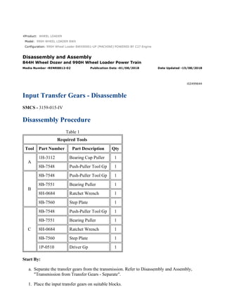
Table 1
Required Tools
Tool Part Number Part Description Qty
A
1H-3112 Bearing Cup Puller 1
8B-7548 Push-Puller Tool Gp 1
B
8B-7548 Push-Puller Tool Gp 1
8B-7551 Bearing Puller 1
8H-0684 Ratchet Wrench 1
8B-7560 Step Plate 1
C
8B-7548 Push-Puller Tool Gp 1
8B-7551 Bearing Puller 1
8H-0684 Ratchet Wrench 1
8B-7560 Step Plate 1
1P-0510 Driver Gp 1
Start By:
a. Separate the transfer gears from the transmission. Refer to Disassembly and Assembly,
"Transmission from Transfer Gears - Separate".
1. Place the input transfer gears on suitable blocks.
1/8
990H Wheel Loader BWX00001-UP (MACHINE) POWERED BY C27 Engine(SEBP...
2021/11/25
https://127.0.0.1/sisweb/sisweb/techdoc/techdoc_print_page.jsp?returnurl=/sis...
2. Illustration 1 g00862308
2. Remove bolts (1) from manifold (2).
Note: Bolts (1) can be used as forcing screws in order to loosen manifold (2).
3. Remove manifold (2).
Illustration 2 g00862309
4. Remove O-ring seal (3) and O-ring seal (4) from manifold (2).
Illustration 3 g00862310
2/8
990H Wheel Loader BWX00001-UP (MACHINE) POWERED BY C27 Engine(SEBP...
2021/11/25
https://127.0.0.1/sisweb/sisweb/techdoc/techdoc_print_page.jsp?returnurl=/sis...
3. 5. Remove bolts (5) from input bearing cage (6).
Note: Bolts (5) can be used as forcing screws in order to loosen input bearing cage (6).
6. Remove input bearing cage (6) from the transfer case assembly.
Illustration 4 g00862311
Illustration 5 g00512372
Typical Example
7. Remove O-ring seal (7) from the bearing cage.
8. Use Tooling (A) in order to remove bearing cup (8) from the bearing cage.
3/8
990H Wheel Loader BWX00001-UP (MACHINE) POWERED BY C27 Engine(SEBP...
2021/11/25
https://127.0.0.1/sisweb/sisweb/techdoc/techdoc_print_page.jsp?returnurl=/sis...
4. Illustration 6 g00862312
9. Remove lip seal (9) from input bearing cage (6).
Illustration 7 g00862313
10. Remove input gear assembly (10) from the transfer case.
Illustration 8 g00862315
4/8
990H Wheel Loader BWX00001-UP (MACHINE) POWERED BY C27 Engine(SEBP...
2021/11/25
https://127.0.0.1/sisweb/sisweb/techdoc/techdoc_print_page.jsp?returnurl=/sis...
5. Illustration 9 g00862666
11. Use Tooling (B) in order to remove bearing cones (11) from input gear assembly (10).
Illustration 10 g00862316
12. Use Tooling (A) in order to remove bearing cup (12).
13. Remove shim pack (13) from the transfer case assembly.
5/8
990H Wheel Loader BWX00001-UP (MACHINE) POWERED BY C27 Engine(SEBP...
2021/11/25
https://127.0.0.1/sisweb/sisweb/techdoc/techdoc_print_page.jsp?returnurl=/sis...
6. Illustration 11 g00862317
14. Turn over the transfer case assembly, as shown.
15. Remove bolts (14) from output bearing cage (15).
Note: Use bolts (14) as forcing screws, if necessary.
Illustration 12 g00862319
16. Use Tooling (A) in order to remove bearing cup (16) from output bearing cage (15).
Illustration 13 g00862320
17. Remove shim pack (17) and output gear assembly (18) from transfer case assembly.
6/8
990H Wheel Loader BWX00001-UP (MACHINE) POWERED BY C27 Engine(SEBP...
2021/11/25
https://127.0.0.1/sisweb/sisweb/techdoc/techdoc_print_page.jsp?returnurl=/sis...
7. Illustration 14 g00862321
Illustration 15 g00862687
Typical Example
18. Use Tooling (C) in order to remove bearing cones (19) from output gear assembly (18).
Illustration 16 g00862322
19. Remove tube (20) and dowel (21) from the transfer case assembly.
20. Use Tooling (A) in order to remove bearing cup (22).
7/8
990H Wheel Loader BWX00001-UP (MACHINE) POWERED BY C27 Engine(SEBP...
2021/11/25
https://127.0.0.1/sisweb/sisweb/techdoc/techdoc_print_page.jsp?returnurl=/sis...
8. Product: WHEEL LOADER
Model: 990H WHEEL LOADER BWX
Configuration: 990H Wheel Loader BWX00001-UP (MACHINE) POWERED BY C27 Engine
Disassembly and Assembly
844H Wheel Dozer and 990H Wheel Loader Power Train
Media Number -RENR8812-02 Publication Date -01/08/2018 Date Updated -15/08/2018
i02499645
Input Transfer Gears - Assemble
SMCS - 3159-016-IV
Assembly Procedure
Table 1
Required Tools
Tool Part Number Part Description Qty
A 8T-5096 Dial Indicator Group 1
B 1P-0520 Driver Gp 1
Illustration 1 g00862322
1. Place the transfer case in a horizontal position.
2. Lower the temperature of bearing cup (22). Install bearing cup (22) in the transfer case.
Note: The bearing cups must be seated in the transfer case.
1/7
990H Wheel Loader BWX00001-UP (MACHINE) POWERED BY C27 Engine(SEBP...
2021/11/25
https://127.0.0.1/sisweb/sisweb/techdoc/techdoc_print_page.jsp?returnurl=/sis...
9. 3. Install tube (20) and dowel (21) into the transfer case assembly.
Illustration 2 g00862321
4. Raise the temperature of bearing cones (19) to a maximum temperature of 135 °C (275 °F).
Install the bearings on output transfer gear (18).
Note: The bearing cones must be seated on the gear.
Illustration 3 g00862320
5. Install output transfer gear (18) and shim pack (17) in the transfer case assembly.
2/7
990H Wheel Loader BWX00001-UP (MACHINE) POWERED BY C27 Engine(SEBP...
2021/11/25
https://127.0.0.1/sisweb/sisweb/techdoc/techdoc_print_page.jsp?returnurl=/sis...
10. Illustration 4 g00862319
6. Lower the temperature of bearing cup (16) and install the bearing cup in the output bearing
cage. The bearing cup (16) must be seated in output bearing cage (15).
7. The following steps are used in order to set the bearing end play for the lower transfer gear.
a. With the axis of the output gear in a vertical position, install output bearing cage (15)
in the transfer case assembly. Make sure that the bearing cage does not bind in the
transfer case assembly.
Illustration 5 g00662057
b. Install bolts (14). Tighten the bolts evenly to torque of 47 ± 9 N·m (35 ± 7 lb ft).
Rotate the gear for a minimum of three revolutions or rotate the gear until the rolling
resistance of the gear diminishes to a steady level.
Illustration 6 g00661363
Typical Example
c. Mount Tooling (A) on the input transfer gear housing, as shown. Measure the end
play of the gear assembly by lifting on the gear assembly.
Note: The desired end play for the gear is 0.152 mm (.0060 inch). The maximum end
play for the gear is 0.203 mm (.0080 inch). The end play of the gear must be
measured with a dial indicator in order to determine the correct gear end play.
3/7
990H Wheel Loader BWX00001-UP (MACHINE) POWERED BY C27 Engine(SEBP...
2021/11/25
https://127.0.0.1/sisweb/sisweb/techdoc/techdoc_print_page.jsp?returnurl=/sis...
11. d. If the end play is not within the correct range, perform Steps 7.a through 7.c again.
Add or remove shims in order to achieve the correct end play.
Illustration 7 g00862316
8. Turn over the transfer case assembly.
9. Lower the temperature of bearing cup (12) and install the bearing cup in the transfer case
assembly. Use the appropriate equipment in order to handle the bearing cup. The bearing
cup (12) must be seated in transfer case assembly.
10. Install shim pack (13).
Illustration 8 g00862315
11. Raise the temperature of bearing cones (11) to a maximum temperature of 135 °C (275°F).
Install the bearing cones on input transfer gear (10), as shown. The bearing cones must be
seated on the gear properly.
4/7
990H Wheel Loader BWX00001-UP (MACHINE) POWERED BY C27 Engine(SEBP...
2021/11/25
https://127.0.0.1/sisweb/sisweb/techdoc/techdoc_print_page.jsp?returnurl=/sis...
12. Illustration 9 g00862313
12. Install input gear (10) into the transfer case assembly.
Illustration 10 g00862312
13. Install lip seal (9) into input bearing cage (6). Install the seal so that the lip is facing toward
the outside of the input bearing cage. Install the seal until the seal makes contact with the
counterbore in the bearing cage.
Illustration 11 g00862311
5/7
990H Wheel Loader BWX00001-UP (MACHINE) POWERED BY C27 Engine(SEBP...
2021/11/25
https://127.0.0.1/sisweb/sisweb/techdoc/techdoc_print_page.jsp?returnurl=/sis...
13. 14. Lower the temperature of bearing cup (8) and install the bearing cup in the input bearing
cage. Use the appropriate equipment in order to handle the bearing cup. The bearing cup (8)
must be seated in input bearing cage (6).
15. Install O-ring seal (7) in input bearing cage.
Illustration 12 g00661961
16. With the axis of the input gear in a vertical position, install input bearing cage (6) in the
transfer case assembly. Make sure that the bearing cage does not bind in the transfer case
assembly.
17. Install bolts (5). Tighten the bolts evenly to torque of 47 ± 9 N·m (35 ± 7 lb ft).
18. Rotate the shaft while tapping the shaft lightly with a mallet, for a minimum of three
revolutions or until the rolling resistance of the gear diminishes to a steady level.
Illustration 13 g00661394
Typical Example
19. Attach Tooling (A) on the transfer case assembly, as shown.
20. Measure the end play of the gear assembly by lifting on the gear assembly.
Note: The desired end play for the gear is 0.152 mm (.0060 inch). The maximum end play
for the gear is 0.203 mm (.0080 inch). The end play of the gear must be measured with a
dial indicator in order to determine the correct gear end play.
6/7
990H Wheel Loader BWX00001-UP (MACHINE) POWERED BY C27 Engine(SEBP...
2021/11/25
https://127.0.0.1/sisweb/sisweb/techdoc/techdoc_print_page.jsp?returnurl=/sis...
14. 21. If the end play is not within the correct range, repeat Steps 16 through 20. Add or remove
shims in order to achieve the correct end play.
Illustration 14 g00862309
22. Install the O-ring seal (3) and O-ring seal (4) to manifold (2).
Illustration 15 g00862308
23. Use bolts (1) in order to install manifold (2) on the transfer case assembly.
End By:
a. Connect the transfer gears to the transmission. Refer to Disassembly and Assembly,
"Transmission to Transfer Gears - Connect".
7/7
990H Wheel Loader BWX00001-UP (MACHINE) POWERED BY C27 Engine(SEBP...
2021/11/25
https://127.0.0.1/sisweb/sisweb/techdoc/techdoc_print_page.jsp?returnurl=/sis...
15. Product: WHEEL LOADER
Model: 990H WHEEL LOADER BWX
Configuration: 990H Wheel Loader BWX00001-UP (MACHINE) POWERED BY C27 Engine
Disassembly and Assembly
844H Wheel Dozer and 990H Wheel Loader Power Train
Media Number -RENR8812-02 Publication Date -01/08/2018 Date Updated -15/08/2018
i03454616
Output Transfer Gears - Disassemble
SMCS - 3075-015-OJ
Disassembly Procedure
Table 1
Required Tools
Tool Part Number Part Description Qty
A 1P-7409 Eyebolt 1
B 138-7575 Link Bracket 2
C 1P-0520 Driver Gp 1
D 5J-0490 Bolt 2
Start By:
a. Remove the transfer gears. Refer to Disassembly and Assembly, "Transmission from
Transfer Gears - Separate" for the machine that is being serviced.
b. Remove the magnetic filter screen tube assembly. Refer to Disassembly and Assembly,
"Magnetic Filter Screen and Housing - Remove".
1/19
990H Wheel Loader BWX00001-UP (MACHINE) POWERED BY C27 Engine(SEBP...
2021/11/25
https://127.0.0.1/sisweb/sisweb/techdoc/techdoc_print_page.jsp?returnurl=/sis...
16. Illustration 1 g00865519
1. Remove bolt (1), retainer (2), and the O-ring seal from the transfer shaft.
Illustration 2 g00865520
2. Remove yoke (3) from transfer shaft (4).
Illustration 3 g00865522
2/19
990H Wheel Loader BWX00001-UP (MACHINE) POWERED BY C27 Engine(SEBP...
2021/11/25
https://127.0.0.1/sisweb/sisweb/techdoc/techdoc_print_page.jsp?returnurl=/sis...
17. Illustration 4 g01249719
3. Remove bolts (5) from bearing cage (6).
4. Use Tooling (D) in order to separate bearing cage (6) from the transfer gear case. Tighten
Tooling (D) evenly in order to separate the bearing cage from the transfer gear case
assembly.
Illustration 5 g00865524
5. Remove lip seal (7) from bearing cage (6).
Illustration 6 g00865525
3/19
990H Wheel Loader BWX00001-UP (MACHINE) POWERED BY C27 Engine(SEBP...
2021/11/25
https://127.0.0.1/sisweb/sisweb/techdoc/techdoc_print_page.jsp?returnurl=/sis...
18. 6. Remove ring (8), the race, and roller assembly (9) from bearing cage (6).
Illustration 7 g00865526
7. Remove cup plug (10) from transfer gear case assembly (11).
Illustration 8 g00865527
8. Remove tube (12) from transfer gear case assembly (11), if necessary.
Illustration 9 g00865529
9. Position transfer gear case assembly (11), as shown.
4/19
990H Wheel Loader BWX00001-UP (MACHINE) POWERED BY C27 Engine(SEBP...
2021/11/25
https://127.0.0.1/sisweb/sisweb/techdoc/techdoc_print_page.jsp?returnurl=/sis...
19. 10. Remove bolt (13), retainer (14), and the seal.
Illustration 10 g00865530
11. Remove yoke (15) from transfer shaft (4).
Illustration 11 g00865531
Illustration 12 g01249736
12. Remove bolts (16) from output bearing cage assembly (17).
5/19
990H Wheel Loader BWX00001-UP (MACHINE) POWERED BY C27 Engine(SEBP...
2021/11/25
https://127.0.0.1/sisweb/sisweb/techdoc/techdoc_print_page.jsp?returnurl=/sis...
20. 13. Use Tooling (D) in order to separate output bearing cage (17) from the transfer gear case.
Tighten Tooling (D) evenly in order to separate output bearing cage (17) from the transfer
gear case.
Illustration 13 g01249746
14. Install Tooling (A) onto transfer shaft (4).
15. Use Tooling (A) and a suitable lifting device in order to remove output bearing cage
assembly (17) from transfer gear case assembly (11). The weight of bearing cage assembly
(17) is 254 kg (560 lb).
Illustration 14 g00865540
16. Turn over the output bearing cage assembly.
17. Remove bolts (18A) from output bearing cage assembly (17).
6/19
990H Wheel Loader BWX00001-UP (MACHINE) POWERED BY C27 Engine(SEBP...
2021/11/25
https://127.0.0.1/sisweb/sisweb/techdoc/techdoc_print_page.jsp?returnurl=/sis...
21. Illustration 15 g00865542
18. Position output bearing cage assembly (17) on a suitable press.
19. Press transfer shaft (4) from output bearing cage assembly (17), as shown.
Illustration 16 g00865543
20. Press transfer shaft (4) through output gear (18), as shown. The weight of transfer shaft (4)
is approximately 68 kg (150 lb). The weight of output gear (18) is approximately 79 kg
(175 lb).
Illustration 17 g00865545
7/19
990H Wheel Loader BWX00001-UP (MACHINE) POWERED BY C27 Engine(SEBP...
2021/11/25
https://127.0.0.1/sisweb/sisweb/techdoc/techdoc_print_page.jsp?returnurl=/sis...
22. 21. Remove bearing cup (19) and lip seal (20) from output bearing cage assembly (17).
Illustration 18 g00865546
22. Turn output bearing cage assembly (17), as shown.
23. Remove O-ring seal (21).
Illustration 19 g00865547
24. Remove bearing race (22) from transfer shaft (4).
8/19
990H Wheel Loader BWX00001-UP (MACHINE) POWERED BY C27 Engine(SEBP...
2021/11/25
https://127.0.0.1/sisweb/sisweb/techdoc/techdoc_print_page.jsp?returnurl=/sis...
23. Illustration 20 g00865548
25. Remove bearing cones (26), bearing cup (25), retainer (24), spacer (23), and output gear
(18) from transfer shaft (4).
Illustration 21 g00865562
26. Remove O-ring seal (27) from cover (28).
Illustration 22 g00865563
9/19
990H Wheel Loader BWX00001-UP (MACHINE) POWERED BY C27 Engine(SEBP...
2021/11/25
https://127.0.0.1/sisweb/sisweb/techdoc/techdoc_print_page.jsp?returnurl=/sis...
24. Illustration 23 g00865564
27. Remove bolts (30) and locks (29) from input bearing cage (31).
28. Install Tooling (D) in input bearing cage (31). Tighten Tooling (D) evenly in order to
separate the input bearing cage from the transfer gear case assembly.
29. Remove shim pack (32) from cover (28).
Illustration 24 g00865565
30. Remove bearing cup (33) from input bearing cage (31).
Illustration 25 g00865566
10/19
990H Wheel Loader BWX00001-UP (MACHINE) POWERED BY C27 Engine(SE...
2021/11/25
https://127.0.0.1/sisweb/sisweb/techdoc/techdoc_print_page.jsp?returnurl=/sis...
25. 31. Remove bolts (34) from bearing cage assembly (36).
32. Remove the bearing cage assembly from cover (28).
Note: Remove the secondary steering pump in order to remove bearing cage assembly (36),
if equipped.
33. Remove shim pack (35) from bearing cage assembly (36).
Illustration 26 g00865567
34. Remove O-ring seal (37) and bearing cup (38) from bearing cage assembly (36).
Illustration 27 g00865568
35. Loosen bolts (39). Do not remove bolts (39) at this time.
11/19
990H Wheel Loader BWX00001-UP (MACHINE) POWERED BY C27 Engine(SE...
2021/11/25
https://127.0.0.1/sisweb/sisweb/techdoc/techdoc_print_page.jsp?returnurl=/sis...
26. Illustration 28 g01799337
36. Strike bolts (39) or strike the case near the bearing assembly with a dead blow hammer in
order to loosen lock assembly (44). Do not strike cover (40).
Note: Lock assembly (44) must be loosened before removing cover (40). Removing cover
(40) before lock assembly (44) is loosened may result in personal injury.
Illustration 29 g00865568
37. Remove bolts (39).
38. Remove cover (40) from the transfer gear case assembly.
12/19
990H Wheel Loader BWX00001-UP (MACHINE) POWERED BY C27 Engine(SE...
2021/11/25
https://127.0.0.1/sisweb/sisweb/techdoc/techdoc_print_page.jsp?returnurl=/sis...
27. Illustration 30 g00865569
39. Remove O-ring seals (41) and O-ring seal (42) from cover (40).
Illustration 31 g00865571
40. Remove bolts (43) from cover (28).
41. Remove one-half of lock assembly (44).
13/19
990H Wheel Loader BWX00001-UP (MACHINE) POWERED BY C27 Engine(SE...
2021/11/25
https://127.0.0.1/sisweb/sisweb/techdoc/techdoc_print_page.jsp?returnurl=/sis...
28. Suggest:
If the above button click is invalid.
Please download this document
first, and then click the above link
to download the complete manual.
Thank you so much for reading
29. Illustration 32 g00865573
42. Install Tooling (D) in cover (28). Tighten Tooling (D) evenly in order to separate the cover
from the transfer gear case assembly.
43. Use Tooling (B) and a suitable lifting device in order to remove cover (28) from the transfer
gear case assembly. The weight of cover (28) is approximately 82 kg (180 lb).
Illustration 33 g00865574
44. Attach a suitable lifting device to a flat piece of steel bar stock, and place the bar stock
under the bottom of input gear (45).
45. Lift input gear (45) from the transfer gear case assembly. The weight of input gear (45) is
approximately 50 kg (110 lb).
14/19
990H Wheel Loader BWX00001-UP (MACHINE) POWERED BY C27 Engine(SE...
2021/11/25
https://127.0.0.1/sisweb/sisweb/techdoc/techdoc_print_page.jsp?returnurl=/sis...