Downloaded 26 times
![Page 1 of 3
CALCULATING PUMP DISCHARGE PRESSURE – MADE EASY
Compliments of web@station31.org
www.station31.org/calculating-pump-discharge-pressure.pdf - updated apr 30 2010
Summary: The goal of the pump operator, is to determine what Pump Discharge Pressure he must set for
each supply line or handline. To determine this, the total GPM must be known first. GPM is generally
determined by Nozzle Tip Size. Once the GPM is determined, then Friction Loss can be calculated for
that GPM and the size of the fire hose that will be used. Device pressures must also be added to the Pump
Discharge Pressure for each line.
1) The Officer should determine the fire load and how many Gallons Per Minute of water will be
required, to attempt putting the fire out. Rule of thumb: Big Fire, Big Water (higher GPM).
2) The Nozzle Tip Size is primarily what determines how many Gallons Per Minute can be output
from the nozzle. Memorize what Tip Sizes relate to what GPM, and where these Tips are used.
These numbers are general Rule of Thumb for Station 31:
Smooth/Straight Bore & Master Stream Nozzles
Tip Size GPM
15/16 185 (1 ¾” cross-lays & 1 ¾” pre-connects) [round-up to 200GPM]
1 200 (master stream) [tip: for each 1/8 above 1” add 100GPM]
1 1/8 300 (master stream & 2 ½” pre-connect)
1 1/4 400 (master stream)
1 3/8 500 (deluge & truck/bucket)
1 1/2 600 (deluge & truck/bucket)
1 3/4 800 (deluge & truck/bucket)
2 1000 (deluge & truck/bucket)
Fog Nozzles
Diameter GPM
1 1/2 100 (1 ¾” cross-lays & 1 ¾” pre-connects)
2 1/2 250 (2 ½” pre-connect)
3) Friction Loss is created by the flow of water through the supply or handlines. The smaller the
hose, and the faster motion of water (GPM), the higher the Friction Loss. You must compensate
for the Friction Loss of each supply line or handline, by increasing the pressure that you are
pumping the engine.
However in addition to what you calculate as the pressure/PSI required to compensate for the
Friction Loss, you must also add the pressure/PSI requirements that each other device must have,
that is in your supply or handline setup. These are the common pressure/PSI requirements for each
common device:
50PSI = Smooth/Straight Bore Nozzles used on hand lines.
80PSI = Master Stream Nozzles including Deluge & Truck/Bucket)
100PSI = Fog Stream Nozzles
5PSI = Per Floor of Elevation (or truck height)
5PSI = Standpipe Connection
10PSI = Per Appliance (Gated Wye Connector, Truck 31 itself, etc)](https://image.slidesharecdn.com/calculating-pump-discharge-pressure-made-easy-150526173228-lva1-app6892/75/Calculating-pump-discharge-pressure-made-easy-1-2048.jpg)
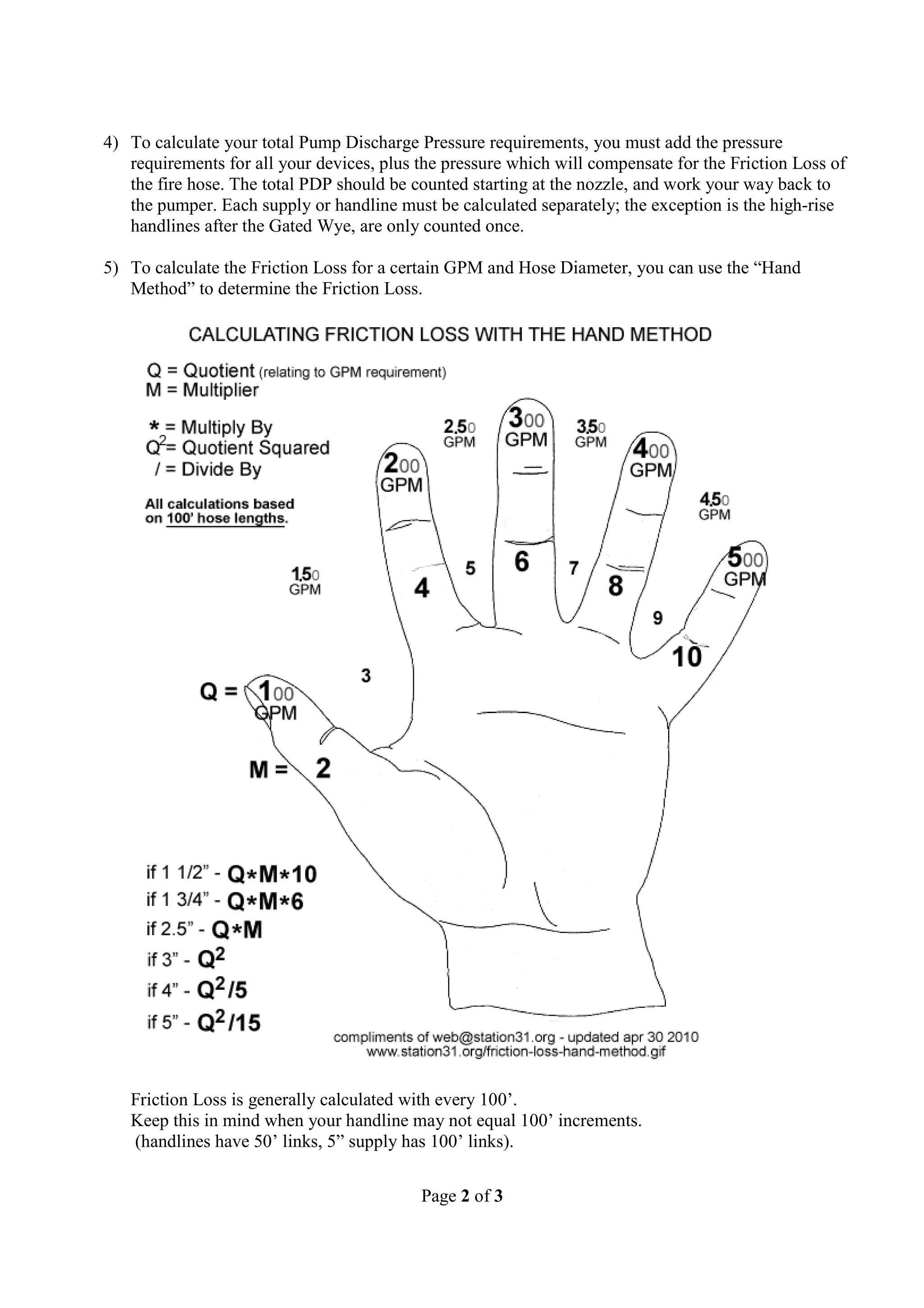
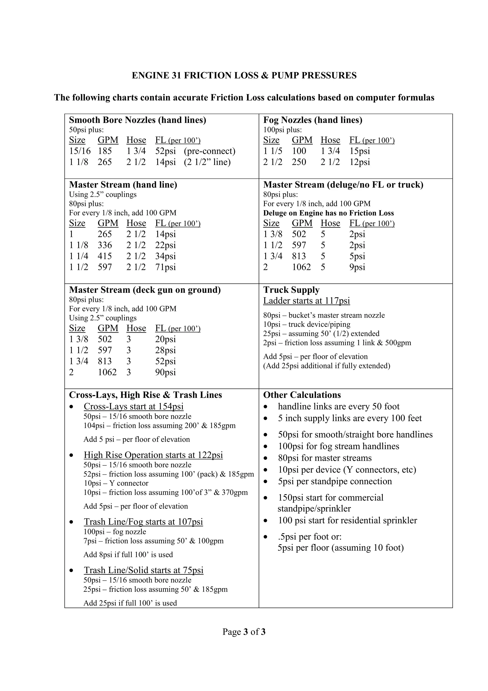

This document provides guidance on calculating pump discharge pressure for firefighting operations. It explains that the total gallons per minute (GPM) must first be determined based on nozzle tip size. Friction loss is then calculated based on hose size and GPM. Device pressures like for nozzles, elevations, and connections are added to determine the total required pump discharge pressure. Charts are included listing common nozzle tip sizes and GPM, hose sizes and their friction loss per 100 feet for different flow rates, and examples of calculating total pressure for different firefighting setups.


