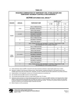
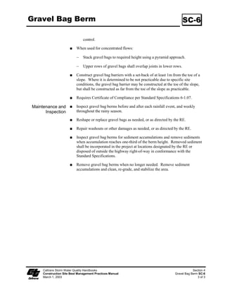
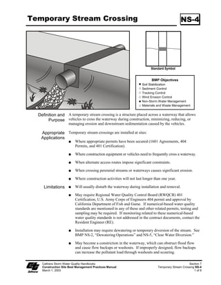
The document provides guidance on best management practices for construction site stormwater pollution prevention. It discusses developing a Stormwater Pollution Prevention Plan and selecting temporary soil stabilization, sediment control, wind erosion control, tracking control, non-stormwater management, and waste management BMPs. Example BMPs included are silt fences, sediment traps, soil binders, stabilized construction entrances, concrete waste management, and material delivery and storage.
![Section 1
Construction Site
Best Management Practices
1.1 Introduction
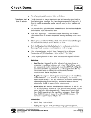
On July 15, 1999, the State Water Resources Control Board (SWRCB) issued the “National
Pollutant Discharge Elimination System (NPDES) Permit, Statewide Storm Water Permit and Waste
Discharge Requirements (WDRs) for the State of California, Department of Transportation
(Caltrans)” (Order No. 99-06-DWQ, NPDES No. CAS000003) hereby called “Permit”. The Permit
regulates storm water discharges from Caltrans properties, facilities and activities, and requires that
Caltrans’ construction program comply with the requirements of the “NPDES General Permit,
Waste Discharge Requirements (WDRs) for Discharges of Storm Water Runoff Associated with
Construction Activity” (Order No. 99-08-DWQ, NPDES No. CAS000002) (General Permit) issued
by the SWRCB, to regulate discharges from construction sites that disturb 5 acres or more.
Beginning March 10, 2003, U.S. Environmental Protection Agency (EPA) and SWRCB regulations
will regulate discharges from projects with soil disturbance of 1 acre or more by amending the
General Permit and thus including coverage of projects with soil disturbance of 1 acre or more.
SWRCB Resolution No. 2001-46 modified provisions of the General Permit that require permittees
to implement specific water quality sampling and analytical procedures implemented on a
construction site.
1.2 Storm Water Pollution Prevention Plan (SWPPP) and Water
Pollution Control Program (WPCP)
Caltrans requires contractors to prepare and implement a program to control water pollution
effectively during the construction of all projects (see Standard Specification Section 7-1.01G Water
Pollution). Projects resulting in 0.4 hectares (ha) [1 ac] or more of soil disturbance are subject to the
General Permit. Caltrans Special Provisions require that for larger projects, defined as those
resulting in 0.4 ha (1 ac) or more of soil disturbance, Contractors prepare and submit a Storm Water
Pollution Prevention Plan (SWPPP). When a SWPPP is required for a project, it will satisfy the
requirements of Standard Specification Section 7-1.01G, in addition to meeting other permit
requirements.
Caltrans requires that a Water Pollution Control Program (WPCP) addressing control measures be
prepared and implemented by the construction contractor for projects resulting in soil disturbance of
less than 0.4 ha (1ac). For detailed step-by-step procedures, instructions and templates to prepare a
SWPPP or a WPCP, refer to the Caltrans Storm Water Quality Handbooks, Storm Water Pollution
Prevention Plan (SWPPP) and Water Pollution Control Program (WPCP) Preparation Manual.
Caltrans Storm Water Quality Handbooks
Construction Site Best Management Practices Manual Section 1
March 1, 2003 1 of 5](https://image.slidesharecdn.com/caltransbmphandbook-100304162758-phpapp02/85/Cal-Trans-Bmp-Handbook-7-320.jpg)
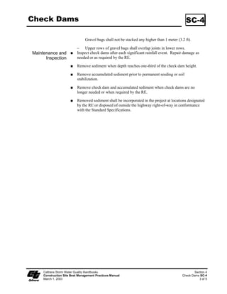
![If two (2) or more small projects [less than 0.4 ha (1 ac) of soil disturbance] in the same corridor are
part of a larger common plan of development [0.4 ha (1 ac) or more], then these small projects are
also subject to the requirements of the General Permit to develop and implement a SWPPP.
1.3 Organization of this Manual
This Storm Water Quality Handbooks, Construction Site Best Management Practices Manual
(manual) is intended to provide Contractors and Caltrans staff with detailed information of
construction site BMPs. This Manual is organized as follows:
Section 1 provides an introduction to the Construction Site Best Management Practices (BMPs)
Manual.
Section 2 provides instructions for the selection and implementation of construction site BMPs.
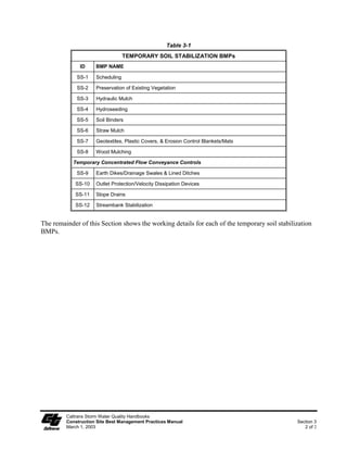
Section 3 provides listing and working details for Caltrans construction site BMPs for
Temporary Soil Stabilization.
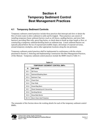
Section 4 provides listing and working details for Caltrans construction site BMPs for
Temporary Sediment Control.
Section 5 provides listing and working details for Caltrans construction site BMPs for Wind
Erosion Control.
Section 6 provides listing and working details for Caltrans construction site BMPs for Tracking
Control.
Section 7 provides listing and working details for Caltrans construction site BMPs for Non-
Storm Water Management.
Section 8 provides listing and working details for Caltrans construction site BMPs for Waste
Management and Materials Pollution Control.
Appendix A provides a listing of frequently used abbreviations, acronyms, and definitions of
terms used throughout this Manual.
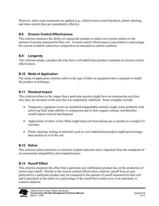
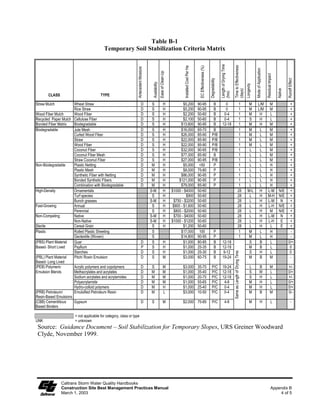
Appendix B provides guidance on the selection of temporary soil stabilization controls.
1.4 Caltrans Construction Site BMPs
This section lists those BMPs considered during the construction of Caltrans projects. Construction
site BMPs (also called temporary control practices) are best conventional technology/best available
technology (BCT/BAT)-based BMPs that are consistent with the BMPs and control practices
required under the General Permit. Caltrans construction site BMPs are divided into six categories
(see Table 1-1):
Caltrans Storm Water Quality Handbooks
Construction Site Best Management Practices Manual Section 1
March 1, 2003 2 of 5](https://image.slidesharecdn.com/caltransbmphandbook-100304162758-phpapp02/85/Cal-Trans-Bmp-Handbook-8-320.jpg)
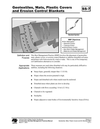
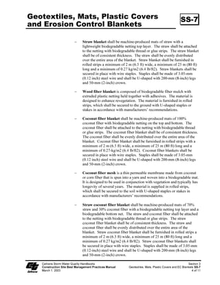
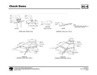
![LQYROYHV WKH SODFHPHQW RI JHRWH[WLOHV
3XUSRVH PDWV SODVWLF FRYHUV RU HURVLRQ FRQWURO EODQNHWV WR VWDELOL]H GLVWXUEHG VRLO DUHDV
DQG SURWHFW VRLOV IURP HURVLRQ E ZLQG RU ZDWHU 7KLV LV RQH RI ILYH WHPSRUDU
VRLO VWDELOL]DWLRQ DOWHUQDWLYHV WR FRQVLGHU
$SSURSULDWH 7KHVH PHDVXUHV DUH XVHG ZKHQ GLVWXUEHG VRLOV PD EH SDUWLFXODUO GLIILFXOW WR
$SSOLFDWLRQV VWDELOL]H LQFOXGLQJ WKH IROORZLQJ VLWXDWLRQV
6WHHS VORSHV JHQHUDOO VWHHSHU WKDQ 9+](https://image.slidesharecdn.com/caltransbmphandbook-100304162758-phpapp02/85/Cal-Trans-Bmp-Handbook-47-320.jpg)
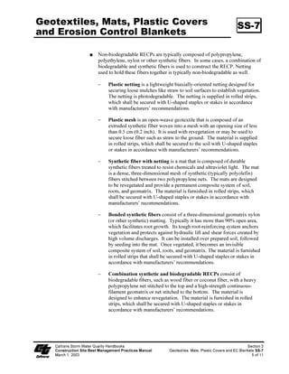
![%ODQNHWV DQG PDWV PXVW EH UHPRYHG DQG GLVSRVHG RI SULRU WR DSSOLFDWLRQ RI
SHUPDQHQW VRLO VWDELOL]DWLRQ PHDVXUHV
3ODVWLF VKHHWLQJ LV HDVLO YDQGDOL]HG HDVLO WRUQ SKRWRGHJUDGDEOH DQG PXVW
EH GLVSRVHG RI DW D ODQGILOO
3ODVWLF UHVXOWV LQ UXQRII ZKLFK PD FDXVH VHULRXV HURVLRQ SUREOHPV LQ
WKH DUHDV UHFHLYLQJ WKH LQFUHDVHG IORZ
7KH XVH RI SODVWLF VKDOO EH OLPLWHG WR FRYHULQJ VWRFNSLOHV RU YHU VPDOO JUDGHG
DUHDV IRU VKRUW SHULRGV RI WLPH VXFK DV WKURXJK RQH LPPLQHQW VWRUP HYHQW](https://image.slidesharecdn.com/caltransbmphandbook-100304162758-phpapp02/85/Cal-Trans-Bmp-Handbook-52-320.jpg)
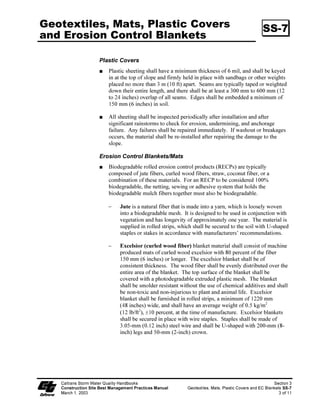
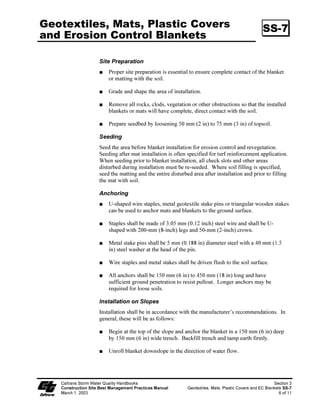
![*HRWH[WLOHV 0DWV 3ODVWLF RYHUV 66
DQG (URVLRQ RQWURO %ODQNHWV
1RQELRGHJUDGDEOH 5(3V DUH WSLFDOO FRPSRVHG RI SROSURSOHQH
SROHWKOHQH QORQ RU RWKHU VQWKHWLF ILEHUV ,Q VRPH FDVHV D FRPELQDWLRQ RI
ELRGHJUDGDEOH DQG VQWKHWLF ILEHUV LV XVHG WR FRQVWUXFW WKH 5(3 1HWWLQJ
XVHG WR KROG WKHVH ILEHUV WRJHWKHU LV WSLFDOO QRQELRGHJUDGDEOH DV ZHOO
- 3ODVWLF QHWWLQJ LV D OLJKWZHLJKW ELD[LDOORULHQWHG QHWWLQJ GHVLJQHG IRU
VHFXULQJ ORRVH PXOFKHV OLNH VWUDZ WR VRLO VXUIDFHV WR HVWDEOLVK YHJHWDWLRQ
7KH QHWWLQJ LV SKRWRGHJUDGDEOH 7KH QHWWLQJ LV VXSSOLHG LQ UROOHG VWULSV
ZKLFK VKDOO EH VHFXUHG ZLWK 8VKDSHG VWDSOHV RU VWDNHV LQ DFFRUGDQFH
ZLWK PDQXIDFWXUHUV¶ UHFRPPHQGDWLRQV
- 3ODVWLF PHVK LV DQ RSHQZHDYH JHRWH[WLOH WKDW LV FRPSRVHG RI DQ
H[WUXGHG VQWKHWLF ILEHU ZRYHQ LQWR D PHVK ZLWK DQ RSHQLQJ VL]H RI OHVV
WKDQ FP LQFK](https://image.slidesharecdn.com/caltransbmphandbook-100304162758-phpapp02/85/Cal-Trans-Bmp-Handbook-95-320.jpg)
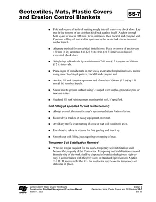
![$OZDV FRQVXOW WKH PDQXIDFWXUHU¶V UHFRPPHQGDWLRQV IRU LQVWDOODWLRQ
'R QRW GULYH WUDFNHG RU KHDY HTXLSPHQW RYHU PDW
$YRLG DQ WUDIILF RYHU PDWWLQJ LI ORRVH RU ZHW VRLO FRQGLWLRQV H[LVW
8VH VKRYHOV UDNHV RU EURRPV IRU ILQH JUDGLQJ DQG WRXFK XS
6PRRWK RXW VRLO ILOOLQJ MXVW H[SRVLQJ WRS QHWWLQJ RI PDW
7HPSRUDU 6RLO 6WDELOL]DWLRQ 5HPRYDO
:KHQ QR ORQJHU UHTXLUHG IRU WKH ZRUN WHPSRUDU VRLO VWDELOL]DWLRQ VKDOO
EHFRPH WKH SURSHUW RI WKH RQWUDFWRU 7HPSRUDU VRLO VWDELOL]DWLRQ UHPRYHG
IURP WKH VLWH RI WKH ZRUN VKDOO EH GLVSRVHG RI RXWVLGH WKH KLJKZD ULJKWRI
ZD LQ FRQIRUPDQFH ZLWK WKH SURYLVLRQV LQ 6WDQGDUG 6SHFLILFDWLRQV 6HFWLRQ
,I DSSURYHG E WKH 5( WKH FRQWUDFWRU PD OHDYH WKH WHPSRUDU VRLO
VWDELOL]HU LQ SODFH
8hy‡…h†ÃT‡‚…€ÃXh‡r…ÃRˆhyv‡’ÃChqi‚‚x† Trp‡v‚Ã
8‚†‡…ˆp‡v‚ÃTv‡rÃ7r†‡ÃHhhtr€r‡ÃQ…hp‡vpr†ÃHhˆhy Br‚‡r‘‡vyr†ÃHh‡†ÃQyh†‡vpÃ8‚‰r…†ÃhqÃ@8Ã7yhxr‡†ÃTT
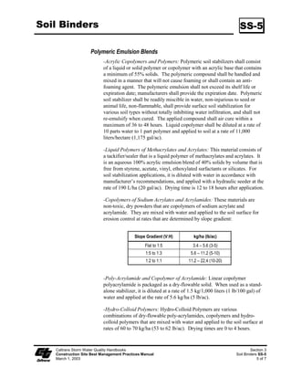
Hh…puà Ã! 'ÂsÃ](https://image.slidesharecdn.com/caltransbmphandbook-100304162758-phpapp02/85/Cal-Trans-Bmp-Handbook-148-320.jpg)
![*HRWH[WLOHV 0DWV 3ODVWLF RYHUV 66
DQG (URVLRQ RQWURO %ODQNHWV
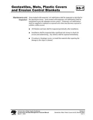
0DLQWHQDQFH DQG $UHDV WUHDWHG ZLWK WHPSRUDU VRLO VWDELOL]DWLRQ VKDOO EH LQVSHFWHG DV VSHFLILHG LQ
,QVSHFWLRQ WKH VSHFLDO SURYLVLRQV $UHDV WUHDWHG ZLWK WHPSRUDU VRLO VWDELOL]DWLRQ VKDOO EH
PDLQWDLQHG WR SURYLGH DGHTXDWH HURVLRQ FRQWURO 7HPSRUDU VRLO VWDELOL]DWLRQ
VKDOO EH UHDSSOLHG RU UHSODFHG RQ H[SRVHG VRLOV ZKHQ DUHD EHFRPHV H[SRVHG RU
H[KLELWV YLVLEOH HURVLRQ
$OO EODQNHWV DQG PDWV VKDOO EH LQVSHFWHG SHULRGLFDOO DIWHU LQVWDOODWLRQ
,QVWDOODWLRQ VKDOO EH LQVSHFWHG DIWHU VLJQLILFDQW UDLQ VWRUPV WR FKHFN IRU
HURVLRQ DQG XQGHUPLQLQJ $Q IDLOXUHV VKDOO EH UHSDLUHG LPPHGLDWHO
,I ZDVKRXW RU EUHDNDJH RFFXUV UHLQVWDOO WKH PDWHULDO DIWHU UHSDLULQJ WKH
GDPDJH WR WKH VORSH RU FKDQQHO
8hy‡…h†ÃT‡‚…€ÃXh‡r…ÃRˆhyv‡’ÃChqi‚‚x† Trp‡v‚Ã
8‚†‡…ˆp‡v‚ÃTv‡rÃ7r†‡ÃHhhtr€r‡ÃQ…hp‡vpr†ÃHhˆhy Br‚‡r‘‡vyr†ÃHh‡†ÃQyh†‡vpÃ8‚‰r…†ÃhqÃ@8Ã7yhxr‡†ÃTT
Hh…puà Ã! (ÂsÃ](https://image.slidesharecdn.com/caltransbmphandbook-100304162758-phpapp02/85/Cal-Trans-Bmp-Handbook-149-320.jpg)
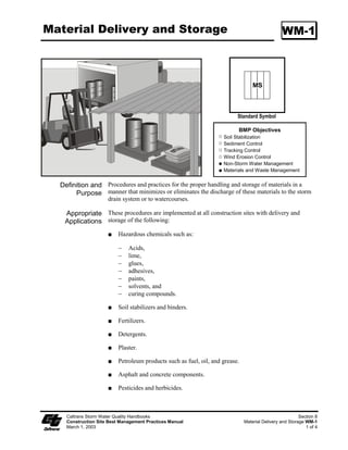
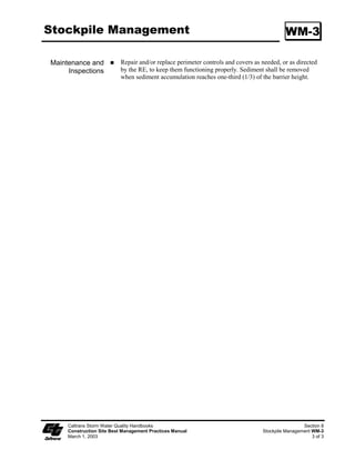
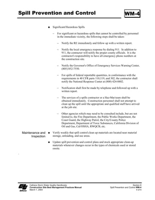
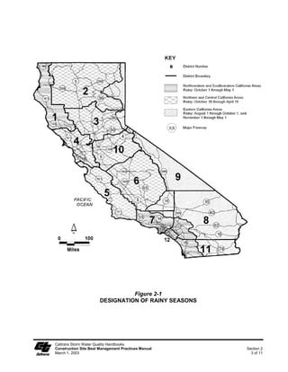
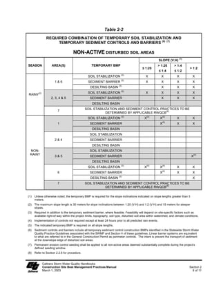
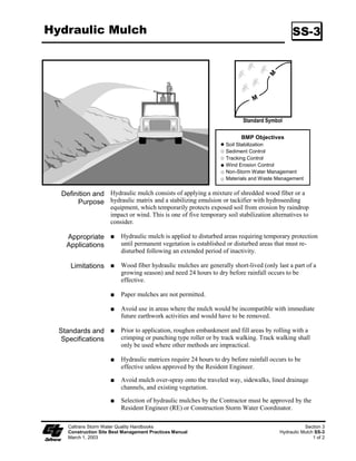
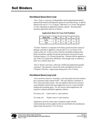
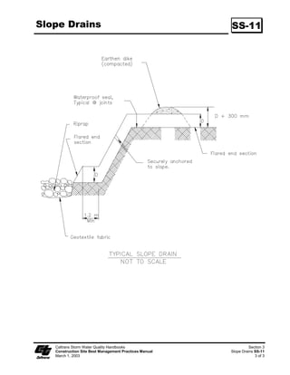
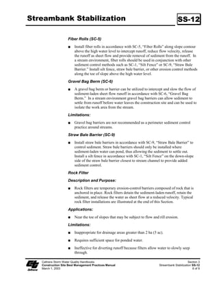
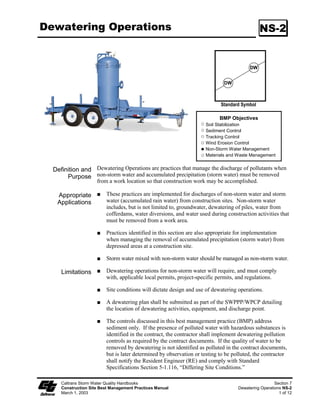
![Streambank Stabilization SS-12
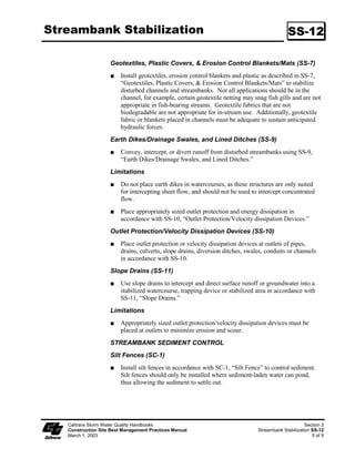
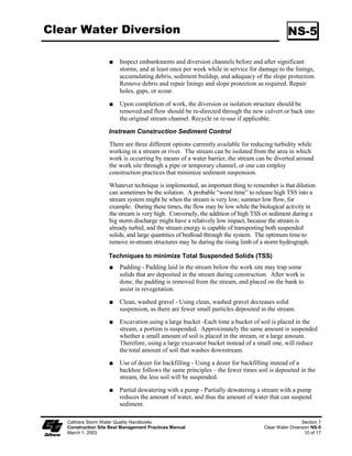
Equipment Selection
Select equipment that reduces the amount of pressure exerted on the ground
surface, and therefore, reduces erosion potential and/or use overhead or aerial
access for transporting equipment across drainage channels. Use equipment
that exerts ground pressures of less than 5 or 6 pounds per square inch (PSI),
where possible. Low ground pressure equipment includes: wide or high
flotation tires (860 to 1850 mm [34 to 72 in] wide); dual tires; bogie axle
systems; tracked machines; lightweight equipment; and, central tire inflation
systems.
STREAMBANK STABILIZATION
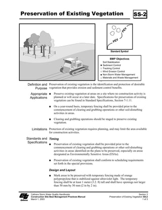
Preservation of Existing Vegetation (SS-2)
Preserve existing vegetation in accordance with SS-2, “Preservation of
Existing Vegetation.” In a streambank environment preservation of existing
vegetation provides the following benefits:
Water Quality Protection:
Vegetated buffers on slopes trap sediment and promote groundwater recharge.
The buffer width needed to maintain water quality ranges from 5 to 30 m (16 to
98 ft). On gradual slopes, most of the filtering occurs within the first 10 m (33 ft).
Steeper slopes require a greater width of vegetative buffer to provide water
quality benefits.
Streambank Stabilization:
The root system of riparian vegetation stabilizes streambanks by increasing
tensile strength in the soil. The presence of vegetation modifies the moisture
condition of slopes (infiltration, evapotranspiraton, interception) and increases
bank stability.
Riparian Habitat
Buffers of diverse riparian vegetation provide food and shelter for riparian
and aquatic organisms. Minimizing impacts to fisheries habitat is a major
concern when working near streams and rivers. Riparian vegetation provides
shade, shelter, organic matter (leaf detritus and large woody debris), and other
nutrients that are necessary for fish and other aquatic organisms. Buffer
widths for habitat concerns are typically wider than those recommended for
water quality concerns (30 to 500 m [98 to 1,640 ft]).
When working near watercourses, it is important to understand the work site’s
placement in the watershed. Riparian vegetation in the headwater streams has
a greater impact on overall water quality than vegetation in downstream
reaches. Preserving existing vegetation upstream is necessary to maintain
water quality, minimize bank failure, and maximize riparian habitat
downstream of the work site.
Caltrans Storm Water Quality Handbooks Section 3
Construction Site Best Management Practices Manual Streambank Stabilization SS-12
March 1, 2003 3 of 9](https://image.slidesharecdn.com/caltransbmphandbook-100304162758-phpapp02/85/Cal-Trans-Bmp-Handbook-166-320.jpg)
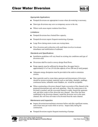
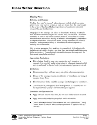
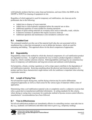
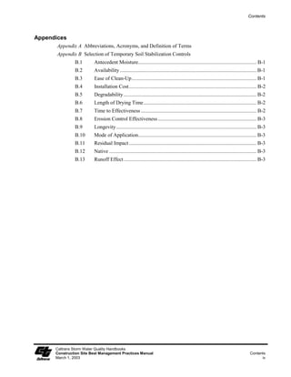
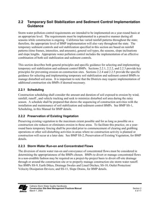
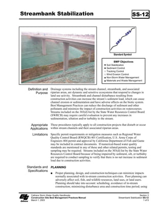
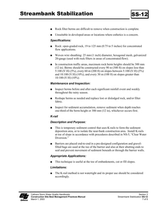
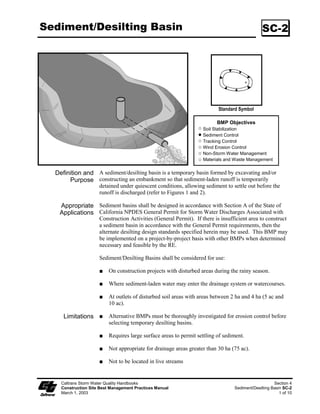
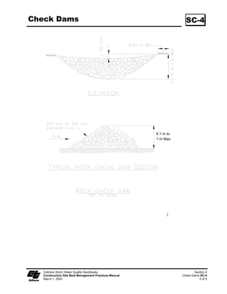
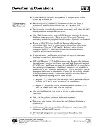
![Sediment/Desilting Basin SC-2
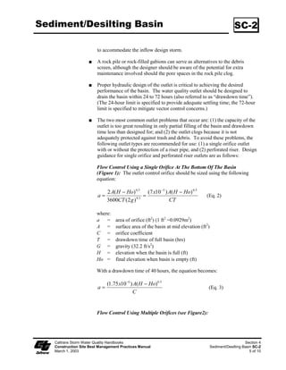
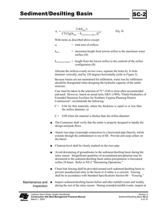
2 A(hmax )
at Ζ (Eq. 4)
CT (2 g[hmax ϑ hcentroid of orifices ]) 0.5
With terms as described above except:
at = total area of orifices
hmax = maximum height from lowest orifice to the maximum water
surface (ft)
hcentroid of orifices = height from the lowest orifice to the centroid of the orifice
configuration (ft)
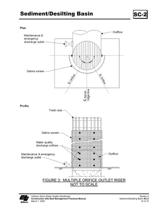
Allocate the orifices evenly on two rows; separate the holes by 3x hole
diameter vertically, and by 120 degrees horizontally (refer to Figure 3).
Because basins are not maintained for infiltration, water loss by infiltration
should be disregarded when designing the hydraulic capacity of the outlet
structure.
Care must be taken in the selection of C; 0.60 is most often recommended
and used. However, based on actual tests, GKY (1989), Outlet Hydraulics of
Extended Detention Facilities for Northern Virginia Planning District
Commission, recommends the following:
C = 0.66 for thin materials; where the thickness is equal to or less than
the orifice diameter, or
C = 0.80 when the material is thicker than the orifice diameter
The Contractor shall verify that the outlet is properly designed to handle the
design and peak flows.
Attach riser pipe (watertight connection) to a horizontal pipe (barrel), which
extends through the embankment to toe of fill. Provide anti-seep collars on
the barrel.
Cleanout level shall be clearly marked on the riser pipe
Avoid dewatering of groundwater to the sediment/desilting basin during the
rainy season. Insignificant quantities of accumulated precipitation may be
dewatered to the sediment/desilting basin unless precipitation is forecasted
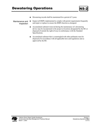
within 24 hours. Refer to NS-2 “Dewatering Operations.”
Chain link fencing shall be provided around each sediment/desilting basin to
prevent unauthorized entry to the basin or if safety is a concern. Fencing
shall be in accordance with Standard Specifications Section 80 – “Fencing.”
Maintenance and Inspect sediment/desilting basins before and after rainfall events and weekly
Inspection during the rest of the rainy season. During extended rainfall events, inspect at
Caltrans Storm Water Quality Handbooks Section 4
Construction Site Best Management Practices Manual Sediment/Desilting Basin SC-2
March 1, 2003 6 of 10](https://image.slidesharecdn.com/caltransbmphandbook-100304162758-phpapp02/85/Cal-Trans-Bmp-Handbook-185-320.jpg)