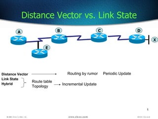
1. Distance Vector Link State Hybrid Distance Vector vs. Link State Route table Topology Incremental Update Periodic Update Routing by rumor A B C D X E
47. OSPF Configuration -2 200.0.0.17 200.0.0.9 200.0.0.10 200.0.0.13 200.0.0.14 200.0.0.33 200.0.0.18 200.0.0.34 255.255.255.240 255.255.255.252 255.255.255.252 255.255.255.224 R1# config t Enter configuration commands, one per line. End with CNTL/Z. R1(config)# router ospf 1 R1(config-router)# network 200.0.0.16 0.0.0.15 area 0 R1(config-router)# network 200.0.0. 8 0.0.0.3 area 0 R1(config-router)# ^Z R3# config t Enter configuration commands, one per line. End with CNTL/Z. R3(config)# router ospf 1 R3(config-router)# network 200.0.0. 32 0.0.0.31 area 0 R3(config-router)# network 200.0.0. 12 0.0.0.3 area 0 R3(config-router)# ^Z R2 R1 R3 S0 S1 E0 S0 E0 S0 A B
48.
49.
50.
51.
52. The show ip route ospf Command RouterA# show ip route ospf Codes: C - connected, S - static, I - IGRP, R - RIP, M - mobile, B - BGP, D - EIGRP, EX - EIGRP external, O - OSPF, IA - OSPF inter area, E1 - OSPF external type 1, E2 - OSPF external type 2, E - EGP, i - IS-IS, L1 - IS-IS level-1, L2 - IS-IS level-2, * - candidate default Gateway of last resort is not set 10.0.0.0 255.255.255.0 is subnetted, 2 subnets O 10.2.1.0 [110/10] via 10.64.0.2, 00:00:50, Ethernet0
53. The show ip ospf interface Command RouterA# show ip ospf interface e0 Ethernet0 is up, line protocol is up Internet Address 10.64.0.1/24, Area 0 Process ID 1, Router ID 10.64.0.1, Network Type BROADCAST, Cost: 10 Transmit Delay is 1 sec, State DROTHER, Priority 1 Designated Router (ID) 10.64.0.2, Interface address 10.64.0.2 Backup Designated router (ID) 10.64.0.1, Interface address 10.64.0.1 Timer intervals configured, Hello 10, Dead 40, Wait 40, Retransmit 5 Hello due in 00:00:04 Neighbor Count is 1, Adjacent neighbor count is 1 Adjacent with neighbor 10.64.0.2 (Designated Router) Suppress hello for 0 neighbor(s)
54. The show ip ospf neighbor Command RouterB# show ip ospf neighbor Neighbor ID Pri State Dead Time Address Interface 10.64.1.1 1 FULL/BDR 00:00:31 10.64.1.1 Ethernet0 10.2.1.1 1 FULL/- 00:00:38 10.2.1.1 Serial0
55. show ip ospf neighbor detail show ip ospf database
80. EIGRP Configuration 200.0.0.17 200.0.0.9 200.0.0.10 200.0.0.13 200.0.0.14 200.0.0.33 200.0.0.18 200.0.0.34 255.255.255.240 255.255.255.252 255.255.255.252 255.255.255.224 R1# config t Enter configuration commands, one per line. End with CNTL/Z. R1(config)# router eigrp 10 R1(config-router)# network 200.0.0.16 R1(config-router)# network 200.0.0. 8 R1(config-router)# ^Z R3# config t Enter configuration commands, one per line. End with CNTL/Z. R3(config)# router eigrp 10 R3(config-router)# network 200.0.0. 32 R3(config-router)# network 200.0.0. 12 R3(config-router)# ^Z R2 R1 R3 S0 S1 E0 S0 E0 S0 A B
81. Verifying the EIGRP Configuration To verify the EIGRP configuration a number of show and debug commands are available. These commands are shown on the next few slides.
82. show ip eigrp topology show ip eigrp topology [active | pending | successors]
83. show ip eigrp topology all-links show ip eigrp traffic
91. Using the show cdp neighbors Command The show cdp neighbor command (sh cdp nei for short) delivers information about directly connected devices.
92.
93. Using the show cdp entry Command The show cdp entry * command displays the same information as the show cdp neighbor details command.
94. Additional CDP Commands The show cdp traffic command displays information about interface traffic, including the number of CDP packets sent and received and the errors with CDP.
112. Creating ACLs ACLs are created in the global configuration mode. There are many different types of ACLs including standard, extended, IPX, AppleTalk, and others. When configuring ACLs on a router, each ACL must be uniquely identified by assigning a number to it. This number identifies the type of access list created and must fall within the specific range of numbers that is valid for that type of list. Since IP is by far the most popular routed protocol, addition ACL numbers have been added to newer router IOSs. Standard IP: 1300-1999 Extended IP: 2000-2699
122. Deny FTP access-list 101 deny tcp any any eq 21 access-list 101 permit ip any any or access-list 101 deny tcp any any eq ftp access-list 101 permit ip any any
DV- the router D will tell C that I know network X, and C will tell B that I know network X and so on, route A does not know anything beyond its neighbor, so its routing by tumor. This also uses periodic update, it also sends the entire routing table, these protocls are based in the early days of internet and some of them are class based. Link state gives much more information, here the link is defined with its interface, IP address, Mask, the type of network its on and its neighbors SO Router A will tell My IP…. This information is passed to router to router and maintain two databases. The topology table is important and its because of topology table the robustness comes. The topology table contains Link state advertisements and the router knows the network topology, any network fails the convergence is faster.
DV will send entire routing table will waste the bandwidth. Link states exchange updates about only Link states Suitable for very large networks
Draw diagram to explain router ID
If the two routers are the only routers on the network, an adjacency should form. If there are more than two routers on the network, adjacencies only form with the designated router (DR) and backup designated router (BDR). If the two routers have already formed adjacencies with the DR and the BDR, they cannot form adjacencies with each other
Backbone Router: Has an interface connected to the backbone (Area 0). Area Border Router (ABR): Has interfaces in multiple areas with at lest one interface in area 0. Connects other areas to the backbone and maintains routing information for each connected area. Autonomous System Boundary Router (ASBR): Router located between OSPF autonomous system and a non-OSPF network. Used to redistribute routing information between networks. Must reside in a non-stub area.
OSPF routers and links are grouped logically into areas that are identified by assigned numbers. All OSPF networks have at least one area with the default being area 0. If more than one area exists, area 0 is defined as the backbone area and is used to connect all other areas. Each area has its own link state databases.
Area 0 should not have more than 30 routers
In order to ensure that a router will become the OSPF DR for any given segment, there are a number of options. One way is to manually configure the interface priority as described in option A above using the "ip ospf priority" interface configuration command. The second method is described in option C. OSPF routers will always use the loopback interface IP address as the router ID, when configured, and the router with the highest IP address will be chosen as the DR when the priorities are the same. The final method is to change the priority of the other routers in the segment to zero. When the OSPF priority is set to 0, the router is ineligible to become the DR or the BDR. Important Note: The OSPF DR/BDR election process is not pre-emptive, so any changes to the network regarding the DR/BDR election process will only occur when the routers are restarted.
When the OSPF process starts, the Cisco IOS uses the highest local active IP address as its OSPF router ID. If there is no active interface, the OSPF process will not start. If the active interface goes down, the OSPF process has no router ID and therefore ceases to function until the interface comes up again.
EIGRP scales the metric of IGRP by a factor of 256. That is because EIGRP uses a metric that is 32 bits long, and IGRP uses a 24-bit metric. EIGRP can multiply or divide by 256 to easily exchange information with IGRP
Purpose : The figure introduces the IGRP routing protocol. IGRP is a sophisticated distance vector routing protocol. Emphasize: The Interior Gateway Routing Protocol (IGRP) is a dynamic distance-vector routing protocol designed by Cisco in the mid-1980s for routing in an autonomous system that contains large, arbitrarily complex networks with diverse bandwidth and delay characteristics. Historically, IGRP became one of the success factors for the early Cisco IOS software capabilities because of its superiority to RIP version 1. The important IGRP characteristics are as follows: More scalability than RIP Fast response to network changes Sophisticated metric Multiple-path support
EIGRP Metrics Another really sweet thing about EIGRP is that unlike many other protocols that use a single factor to compare routes and select the best possible path, EIGRP can use a combination of four: Bandwidth Delay Load Reliability
EIGRP routers that belong to different autonomous systems (ASes) don’t automatically share routing information and they don’t become neighbors. This behavior can be a real benefit when used in larger networks to reduce the amount of route information propagated through a specific AS. The only catch is that you might have to take care of redistribution between the different ASes manually. The only time EIGRP advertises its entire routing table is when it discovers a new neighbor and forms an adjacency with it through the exchange of Hello packets. When this happens, both neighbors advertise their entire routing tables to one another. After each has learned its neighbor’s routes, only changes to the routing table are propagated from then on. When EIGRP routers receive their neighbors’ updates, they store them in a local topology table. This table contains all known routes from all known neighbors, and serves as the raw material from which the best routes are selected and placed into the routing table. EIGRP routers keep route and topology information readily available in RAM, so they can react quickly to changes. Like OSPF, EIGRP saves this information in several tables and databases.
Route source - The identification number of the router that originally advertised that route. This field is populated only for routes learned externally from the EIGRP network.
Reliable Transport Protocol The EIGRP transport mechanism uses a mix of multicast and unicast packets, using reliable delivery when necessary. All transmissions use IP with the protocol type field set to 88. The IP multicast address used is 224.0.0.10. DUAL requires guaranteed and sequenced delivery for some transmissions. This is achieved using acknowledgments and sequence numbers. So, for example, update packets (containing routing table data) are delivered reliably (with sequence numbers) to all neighbors using multicast. Acknowledgment packets-- with the correct sequence number--are expected from every neighbor. If the correct acknowledgment number is not received from a neighbor, the update is retransmitted as a unicast. The sequence number (seq num) in the last packet from the neighbor is recorded to ensure that packets are received in sequence. The number of packets in the queue that might need retransmission is shown as a queue count (QCnt), and the smoothed round trip time (SRTT) is used to estimate how long to wait before retransmitting to the neighbor. The retransmission timeout (RTO) is the time the router will wait for an acknowledgment before retransmitting the packet in the queue. Some transmissions do not require reliable delivery. For example, hello packets are multicast to all neighbors on an Ethernet segment, whereas acknowledgments are unicast. Neither hellos nor acknowledgments are sent reliably. EIGRP also uses queries and replies as part of DUAL. Queries are multicast or unicast using reliable delivery, whereas replies are always reliably unicast. Query and reply packets are discussed in more detail in the next section.
All route computations in EIGRP are handled by DUAL. One of DUAL's tasks is maintaining a table of loop-free paths to every destination. This table is referred to as the topology table . Unlike traditional DV protocols that save only the best (least-cost) path for every destination, DUAL saves all paths in the topology table. The least-cost path(s) is copied from the topology table to the routing table. In the event of a failure, the topology table allows for very quick convergence if another loop-free path is available. If a loop-free path is not found in the topology table, a route recomputation must occur, during which DUAL queries its neighbors, who, in turn, may query their neighbors, and so on... hence the name "Diffusing" Update Algorithm.
Slide 1 of 2 Purpose: This figure explains how to use the router igrp and network commands to configure an IGRP process. Emphasize: Note that the AS keyword is required for IGRP. You can use multiple network commands to specify all networks that are to participate in the IGRP process. Only those networks specified will be published to other routers.
Purpose: The figure shows how the IGRP commands operate on the example network. Emphasize : An administrator only specifies directly connected networks that should be published to other routers. Without the network command, nothing is advertised. With a network command, the router will advertise every subnet within the Class A, B, or C network specified in the configuration.
# Show users – will show connected users # Clear line 1 – will disconnect the session on line 1
Purpose: This chapter introduces the Cisco IOS™ CLI on the Catalyst® 1900 switch and router. Timing: This chapter should take about 2 hours to present. Note: The Catalyst 1900 switch only has a subset of the router Cisco IOS commands available. Contents: Introduction to Cisco IOS. Explain to the student what is IOS? Cisco Device startup procedures in general. IOS configuration source. General introduction to the IOS CLI . Cat 1900 switch startup procedures. Intro to Cat 1900 CLI. This part covers the basic configuration on the switch, like setting the IP address and hostname. More details about the various Cat 1900 switch configuration commands are explained in Chapter 6 and 7. Router startup procedures. More details on the router startup process is discussed in chapter 5. Router IOS CLI.
Note: CDP is sent using multicast frames with the MAC address 0100.0ccc.cccc. CDP is a Cisco proprietary data link layer protocol that operates over any medium that supports the Subnetwork Access Protocol (SNAP) encapsulation (LANs, most WANs, and ATM). It is important to understand that because CDP operates at Layer 2 (data link layer of the OSI model), it functions independently of the Layer 3 (network) protocol (IP or IPX). CDP is on by default, but it can be disabled. In many cases, CDP is disabled on dial backup links, such as ISDN, so as to not keep the link up constantly. CDP – One dependency, the media type at the physical layer must support SNAP. SNAP was created because all protocols does not work well for 802.3 Ethernet frame as 802.3 had no type filed any longer. The original Ethernet had type filed, But the 802.3 had replaced this with length field, so When we bring SNAP at layer 2 it brings back type field. Frame relay, Ethernet, ATM, Token ring all support SNAP
Device ID. The hostname of the neighboring device Local Interface. The interface on which this router received information about the neighboring device. Holdtime. The amount of time the router will store this information before dropping it from memory, if additional CDP packets are not received. Capability. The type of device that announced itself using CDP. Platform. The hardware platform of the neighboring equipment. Port ID. The port from which the CDP packet was sent on the neighboring device. Emphasize: CDP is media- and protocol-independent and runs on all Cisco-manufactured equipment including routers, access servers, switches, and some managed hubs. With CDP, network management applications can retrieve the device type and SNMP agent address of neighboring devices. This capability enables applications to send SNMP queries to neighboring devices. CDP allows network management applications to dynamically discover Cisco devices that are neighbors. CDP runs on all media that support the Subnetwork Access Protocol, including LAN and Frame Relay. CDP runs over the data link layer only, not the network layer. Therefore, two systems that support different network-layer protocols can learn about each other. Cached CDP information is available to network management applications. Cisco devices never forward a CDP packet. When new information is received, old information is discarded. The holdtime determines how long to keep existing information from a neighbor.
Note: Some of the CDP commands are not available on the Catalyst 1900 switch, like cdp run , show cdp traffic , and show cdp entry . It’s important to remember that CDP packets aren’t passed through a Ciscoswitch, and that you see only what’s directly attached. So this means that if your router is connected to a switch, you won’t see any of the devices hooked up to that switch.
Emphasize: This graphic shows the show cdp neighbors command initiated from a router, which displays a summary of the capabilities and access details for the CDP neighbors. The show cdp neighbors detail command shows detailed information about the same devices. Note: If the neighbor is a Catalyst 1900 switch, the switch MAC address is also displayed. If the switch is a 2900xl, its MAC address is not displayed. Device ID. The hostname of the neighboring device Local Interface. The interface on which this router received information about the neighboring device. Holdtime. The amount of time the router will store this information before dropping it from memory, if additional CDP packets are not received. Capability. The neighbor’s capability, such as router, switch, or repeater. The capability codes are listed at the top of the command output. Platform. The hardware platform of the neighboring equipment.( Cisco 2509, Cisco 2511, and Catalyst 5000) Port ID. The port from which the CDP packet was sent on the neighboring device.
Emphasize: The example shows what information can be obtained about RouterA’s neighbor. CDP is one way to learn about other Cisco devices on the network.
Note: The holdtime indicates how long the neighbor information will be kept in the local CDP table.
181-37
Purpose: This slide discuss the initial configurations on the routers and switches. Note: There is no setup mode on the Catalyst 1900 switch.
Layer 2 of 2 Emphasize: An access list is a mechanism for identifying particular traffic. One application of an access list is for filtering traffic into or out of a router interface.
Permission for router Manage IP Traffic Filter packet which pas thru Either can permit or Deny
If u want to permit only one from a network then permit shud be first
Layer 3 of 3 Purpose: Describe an inbound versus outbound access list on an interface.
Layer 3 of 3 Emphasize: Layer 3—Adds the Novell IPX access lists covered in Chapter 11, “Configuring Novell IPX,” and the number ranges for these types of access lists. As of Release 11.2.4(F), IPX also supports named access lists. Point out that number ranges generally allow 100 different access lists per type of protocol. When a given hundred-number range designates a standard access list, the rule is that the next hundred-number range is for extended access lists for that protocol. Exceptions to the numbering classification scheme include AppleTalk and DECnet, where the same number range can identify various access list types. For the most part, number ranges do not overlap between different protocols. Note: With Cisco IOS 12.0, the IP access-lists range has been expanded to also include: <1300-1999> IP standard access list (expanded range) <2000-2699> IP extended access list (expanded range)
Purpose: This graphic gives an overview of the type of TCP/IP packet tests that standard access lists can filter. It uses the encapsulation graphic and diamond decision graphic to remind students of material presented earlier in this course.
Layer 3 of 3 Purpose: Shows a deny result of the access list test. Emphasize: Now the packet is discarded into the packet discard bucket. The unwanted packet has been denied access to the outbound interface. The Notify Sender message shows a process like ICMP, returning an “administratively prohibited” message back to the sender.
Explain how the access list process, here there are three ACLS. Can give the example with a host IP address 192.168.1.1 and host 192.168.1.2 what happens on all the three ACLS
Purpose: This graphic gives an overview of the type of TCP/IP packet tests that extended access lists can filter. It uses the encapsulation graphic and diamond decision graphic to remind students of material presented earlier in this course.
Named access lists allow you to use names to both create and apply either standard or extended access lists. There is nothing new or different about these access lists aside from being able to refer to them in a way that makes sense to humans.
![Distance Vector vs. Link State ,[object Object],[object Object],[object Object],[object Object],[object Object],[object Object],[object Object],[object Object],[object Object],[object Object],[object Object],[object Object]](data:image/gif;base64,R0lGODlhAQABAIAAAAAAAP///yH5BAEAAAAALAAAAAABAAEAAAIBRAA7)