This document is a dissertation submitted by Michael Alan Heath May for the BSc (Hons) Computer Science program at the University of Greenwich. The dissertation discusses the design and development of an independent, ad-hoc communication network called BlueHop that allows smartphone users to contact one another when traditional phone networks are impaired. The document includes sections on literature review, product review, technical review, requirements analysis, design of two prototypes for BlueHop, development details, and evaluation of the project. Testing was conducted and requirements were evaluated to assess how well the prototypes met the objectives of creating a reliable backup network for disaster relief situations.


![47
REFERENCES
Anon. (March 2010) Bluetooth power consumption [Online]. Available from:
http://forum.arduino.cc/index.php?topic=23805.0 [Accessed 04 April 2016].
Arne, M.H. & Asmund, S. (2006) Innovative Techniques for Extremely Low Power Consumption. Atmel
White Paper, 1(1), pp.1-16.
Baoshi. (2012) Project Crystal (Part 1) [Online]. Available from: http://www.ba0sh1.com/project-
crystal-part-1/ [Accessed 04 April 2016].
Coley Consulting. (2015 ) moscow [Online]. Available from:
http://www.coleyconsulting.co.uk/moscow.htm [Accessed 04 April 2016].
commotion. (2016) about [Online]. Available from: https://commotionwireless.net/about/ [Accessed
04 April 2016].
Conti, M. & Giordano, S. (2007) Multihop Ad Hoc Networking: The Reality. IEEE Commun. Mag., 45(4),
pp.88-95.
Conti, M. & Giordano, S. (2007) Multihop Ad Hoc Networking: The Theory. IEEE Commun. Mag., 45(4),
pp.78-86.
fab-lab.eu. (2015) Tame the beast: Ultra-Low Power #ESP8266 Thing [Online]. Available from:
https://www.hackster.io/fablabeu/esp8266-thing-by-sparkfun-982bc6 [Accessed 04 April 2016].
Gee. (March 11 2013) Advantages of Using Likert Scale Questions [Online]. Available from:
https://www.smartsurvey.co.uk/blog/advantages-of-using-likert-scale-questions/ [Accessed 04 April
2016].
Geerling, J. (November 27, 2015) Raspberry Pi Zero - Power Consumption Comparison [Online].
Available from: http://www.jeffgeerling.com/blogs/jeff-geerling/raspberry-pi-zero-power [Accessed 04
April 2016].
Gunaratna, G.T.C., Jayarathna, P.V.N.M., Sandamini, S.S.P. & De Silva, D.S. (2015) Implementing
Wireless Adhoc Networks for Disaster Relief Communication. 2015 8th International Conference on
Ubi-Media Computing (UMEDIA), pp.66-71.
Gunaratna, G.T.C., Jayarathna, P.V.N.M., Sandamini, S.S.P. & De Silva, D.S. (2015) Implementing
Wireless Adhoc Networks for Disaster Relief Communication. 8th International Conference on Ubi-
Media Computing (UMEDIA), pp.66-71.
IDC Research, Inc. (2015) Smartphone OS Market Share, 2015 Q2 [Online]. Available from:
http://www.idc.com/prodserv/smartphone-os-market-share.jsp [Accessed 04 April 2016].
Karamshuk, D., Boldrini, C., Conti, M. & Passarella, A. (2011) Human mobility models for opportunistic
networks. IEEE Commun. Mag, 49(12), pp.157-65.](https://image.slidesharecdn.com/55cf8556-6cd7-490f-ae9c-590595784efc-160517163127/85/BlueHop-FinalReport-53-320.jpg)
![48
Lakshmi, N.R. & Ibe, O. (2012) A joint network for disaster recovery and search and rescue operations.
Computer Networks, (56), pp.3347-73.
Liliana, E.Q. & Luis, M.G. (2014) Behavior of Ad Hoc routing protocols, analyzed for emergency and
rescue. Expert Systems with Applications, 41(5), pp.2565-73.
Nishiyama, H., Ito, M. & Kato, N. (2014) Relay-by-smartphone: realizing multihop device-to-device
communications. IEEE Commun. Mag., 52(4), pp.56-65.
opengarden. (n.d.) How To [Online]. Available from: http://opengarden.com/how-to/ [Accessed 2016].
project, s. (2013) serval project [Online]. Available from: http://www.servalproject.org/ [Accessed 04
April 2016].
Reina, D. et al. (2015) A Survey on Multihop Ad Hoc Networks for Disaster Response Scenarios.
International Journal of Distributed Sensor Networks, pp.1-16.
Schwartz, M. (August 7, 2013) How to Run an Arduino for Years on a Battery [Online]. Available from:
https://www.openhomeautomation.net/arduino-battery/ [Accessed 04 April 2016].
skiwall. (2013) SD Card [Online]. Available from: http://forum.arduino.cc/index.php?topic=149504.0
[Accessed 04 April 2016].
The Economist. (2015) What’s up? [Online]. Available from:
http://www.economist.com/blogs/graphicdetail/2015/03/messaging-apps [Accessed 02 Febuary
2016].](https://image.slidesharecdn.com/55cf8556-6cd7-490f-ae9c-590595784efc-160517163127/85/BlueHop-FinalReport-54-320.jpg)

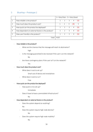

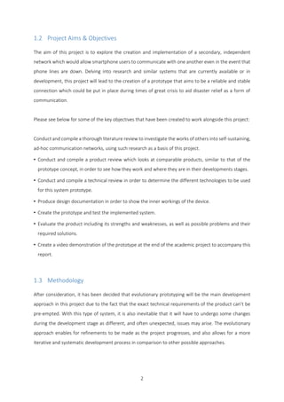
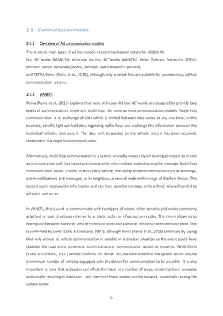
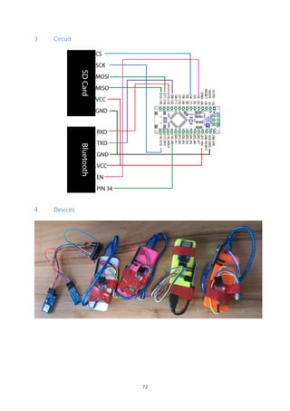
![63
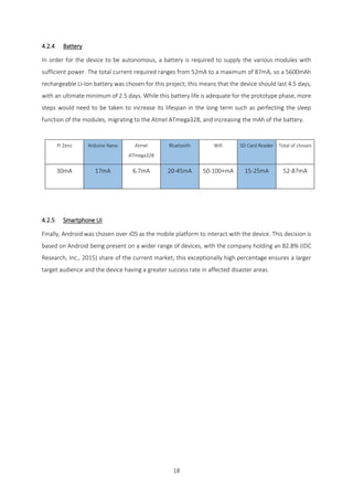
3 Connection
void ConnectionOpen(String add) {
toggleAT();
btCommand(F("AT"));
btCommand(F("AT+INIT"));
btCommand(F("AT+ROLE=1"));
btCommand("AT+BIND=" + add);
Serial.println("Link to ["+add+"]");
btCommand("AT+LINK=" + add);
toggleAT();
}
4 Disconnection
void ConnectionClose() {
toggleAT();
btCommand(F("AT+ROLE=0"));
btCommand(F("AT+BIND=0"));
Serial.println(F("Connection Closed"));
toggleAT();
}](https://image.slidesharecdn.com/55cf8556-6cd7-490f-ae9c-590595784efc-160517163127/85/BlueHop-FinalReport-69-320.jpg)


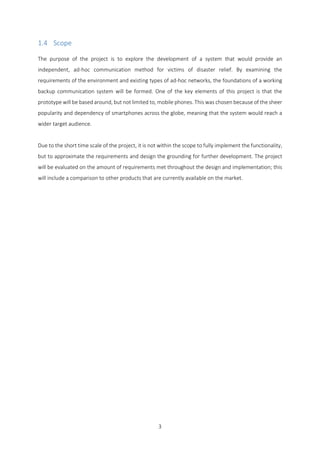
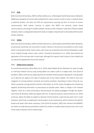
![73
APPENDIX I - Android Connection Manager
1 Start connection
public void startConnection() {
BluetoothAdapter mBluetoothAdapter = BluetoothAdapter.getDefaultAdapter();
Object[] pairedDevices = mBluetoothAdapter.getBondedDevices().toArray();
int le = pairedDevices.length;
int count = 0;
int pos = 0;
if (le > 0) {
for (int i = 0; i < le; i++) {
BluetoothDevice device = (BluetoothDevice) pairedDevices[i];
String address = device.getAddress();
String name = device.getName();
if (name.contains("BlueHop")) {
connection = ("nDevice " + name + " [" + address + "]n");
pos = i;
count++;
}
}
//console.append("nCompatible devices found: " + count);
if (count > 1) {
conText = (connection + "nOnly one BlueHop device should be
paired.");
} else if (count == 0) {
conText = (connection + "nNo devices found, please pair a BlueHop
Node.");
} else if (count == 1) {
try {
device = (BluetoothDevice) pairedDevices[pos];
mmSocket = device.createRfcommSocketToServiceRecord(uuid);
mmSocket.connect();
boS = mmSocket.getOutputStream();
biS = mmSocket.getInputStream();
conText = (connection + "n" + Html.fromHtml("<b>Connection
Successful!</b>"));
connected = true;
} catch (Exception e) {
conText = (connection + "n" + Html.fromHtml("<b>Connection
UnSuccessful!</b>") + "n" + e.toString());
connected = false;
}
}
}
}](https://image.slidesharecdn.com/55cf8556-6cd7-490f-ae9c-590595784efc-160517163127/85/BlueHop-FinalReport-79-320.jpg)
![74
2 Receive
public void recieve() {
String messageTmp = "";
try {
toggleConnection(true);
if (mmSocket.isConnected()) {
String text = "<M>inbox</M>";
char[] output = text.toCharArray();
for (int i = 0; i < output.length; i++) {
boS.write(output[i]);
}
comms.clear();
boolean start=false;
boolean stop=false;
while(!stop){
String mess =readInPacket();
if (mess.contains("<D>")&&!start){
start=true;
}else if (start&&mess.contains("</D>")) {
stop = true;
if (messageTmp!=""){
comms.add(messageTmp);
}
break;
}else if(mess.contains("<Id>")){
if (messageTmp!=""){
comms.add(messageTmp);
}
mess=mess.replace("<Id>", "");
mess=mess.replace("</Id>","");
messageTmp="n "+mess+" :n";
}else{
messageTmp+=mess;
}
}
}
} catch (Exception e) {
}
}](https://image.slidesharecdn.com/55cf8556-6cd7-490f-ae9c-590595784efc-160517163127/85/BlueHop-FinalReport-80-320.jpg)
![76
4 Refresh Address
public ArrayList refreshAddress() {
String input = " ";
try {
toggleConnection(true);
if (mmSocket.isConnected()) {
String text = "<M>addr</M>";
char[] output = text.toCharArray();
for (int i = 0; i < output.length; i++) {
boS.write(output[i]);
}
toggleConnection(false);
Thread.sleep(12000); // see if this time can be shortened
by looking at the mnsocket
toggleConnection(true);
text = "<M>adds</M>";
output = text.toCharArray();
for (int i = 0; i < output.length; i++) {
boS.write(output[i]);
}
availableAddress.clear();
boolean start = false;
boolean end = false;
int timeout = 0;
while (!start || !end) {
input = readIn();
if (input.contains("<D>")) {
start = true;
} else if (input.contains("</D>")) {
end = true;
} else {
availableAddress.add(input);
}
timeout++;
Thread.sleep(100);
if (timeout == 50) {
break;
}
}
}
} catch (Exception e) {
}
return availableAddress;
}](https://image.slidesharecdn.com/55cf8556-6cd7-490f-ae9c-590595784efc-160517163127/85/BlueHop-FinalReport-82-320.jpg)
![78
6 Send
public String send(int target, String text) {
int cutLength=20;
int del=200; // WAS 500
String ret="";
if (!text.isEmpty()) {
toggleConnection(true);
if (connected) {
try {
int tO=100;
Random rand = new Random();
int n = rand.nextInt(999); // generate ID
String nS= String.valueOf(n);
String t = mDec("<con>"+nS+"</con>");
writeOutBt(t);
Thread.sleep(del);
while(tO>0){
String tmp =readIn();
if(tmp.contains("<OK>")){
break;
}else {
Thread.sleep(del);
tO--;
}
}
if (tO>0) { // Divides packets up
ret="Connection confirmed";
String[] tmp = SettingsManager.savedAddress.get(target);
t = mDec("<D>" + tmp[1]);
writeOutBt(t);
Thread.sleep(del);
for (int i = 0; i < text.length(); i += cutLength) {
Thread.sleep(del);
if (i + cutLength > text.length()) {
t = mDec(text.substring(i, text.length()));
writeOutBt(t);
} else {
t = mDec(text.substring(i, i + cutLength));
writeOutBt(t);
comms.add("n" + t);
}
}
Thread.sleep(del);
t = mDec("</D>");
writeOutBt(t);
}
} catch (Exception e) {
ret="Error Sending Message";
}
}
}
return ret;
}](https://image.slidesharecdn.com/55cf8556-6cd7-490f-ae9c-590595784efc-160517163127/85/BlueHop-FinalReport-84-320.jpg)
![79
7 writeOutBt
private void writeOutBt(String t) {
try {
char[] output = t.toCharArray();
for (int i = 0; i < output.length; i++) {
boS.write(output[i]);
}
} catch (Exception e) {
//comms.add("Error Sending Message"+e);
}
}
private String mDec(String t) {
return " <M>" + t + "</M>";
}
8 mDec
private String mDec(String t) {
return " <M>" + t + "</M>";
}](https://image.slidesharecdn.com/55cf8556-6cd7-490f-ae9c-590595784efc-160517163127/85/BlueHop-FinalReport-85-320.jpg)


![Final_projekjljlkjlkjlkjlkjlkct_PPT[1].pptx](https://cdn.slidesharecdn.com/ss_thumbnails/finalprojectppt1-250527163112-5037c4bd-thumbnail.jpg?width=640&height=640&fit=bounds)


![Firechat[2]](https://cdn.slidesharecdn.com/ss_thumbnails/firechat2-160513134816-thumbnail.jpg?width=640&height=640&fit=bounds)


