This document provides specifications for the BeStar SMOOO 3A-42 silicon MEMS microphone. Key details include:
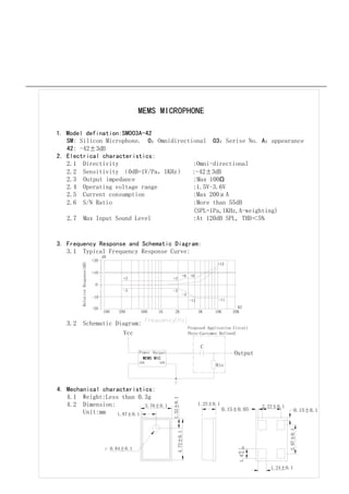
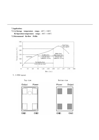
- The microphone has an omnidirectional sensitivity of -42±3 dB at 1 kHz and operates between 1.5-3.6 V.
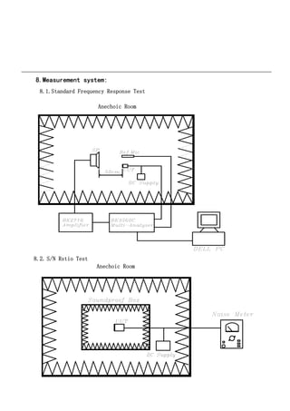
- Frequency response ranges from -11 dB at 20 kHz to +6 dB at 2 kHz.
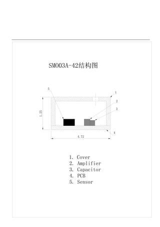
- It measures 1.25 x 1.32 x 3.76 mm and weighs less than 0.3 g.
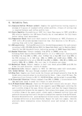
- Reliability tests include reflow, humidity, temperature shock, ESD sensitivity, vibration, and drop tests.
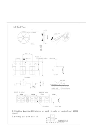
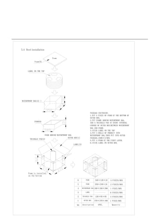
- The microphone is packaged in reels of 4,000 pieces and shipped