Basic Electronic Circuits Problems And Solutions K Vasudevan
Basic Electronic Circuits Problems And Solutions K Vasudevan
Basic Electronic Circuits Problems And Solutions K Vasudevan
Basic Electronic Circuits Problems And Solutions K Vasudevan
Basic Electronic Circuits Problems And Solutions K Vasudevan
1.
Basic Electronic CircuitsProblems And Solutions
K Vasudevan download
https://ebookbell.com/product/basic-electronic-circuits-problems-
and-solutions-k-vasudevan-46152448
Explore and download more ebooks at ebookbell.com
2.
Here are somerecommended products that we believe you will be
interested in. You can click the link to download.
Basic Electronics And Electronic Circuits Learn Electronics And Free
Online Circuit Simulator Stephen Bucaro
https://ebookbell.com/product/basic-electronics-and-electronic-
circuits-learn-electronics-and-free-online-circuit-simulator-stephen-
bucaro-37624876
Basic Electronics Course How To Create Electronic Circuits Basic All
About Circuits Video Lectures Frenner
https://ebookbell.com/product/basic-electronics-course-how-to-create-
electronic-circuits-basic-all-about-circuits-video-lectures-
frenner-232893320
Basic Electronics And Linear Circuits 2nd Edition N N Bhargava S C
Gupta D C Kulshreshtha
https://ebookbell.com/product/basic-electronics-and-linear-
circuits-2nd-edition-n-n-bhargava-s-c-gupta-d-c-kulshreshtha-11865912
Electronics Tutorial A Handbook For Beginners Introduction To Basic
Circuits Benefield
https://ebookbell.com/product/electronics-tutorial-a-handbook-for-
beginners-introduction-to-basic-circuits-benefield-232899130
3.
Basic Electric CircuitsPergamon International Library Of Science
Technology Engineering And Social Studies 2nd Edition Brookes
https://ebookbell.com/product/basic-electric-circuits-pergamon-
international-library-of-science-technology-engineering-and-social-
studies-2nd-edition-brookes-34997124
An Analog Electronics Companion Basic Circuit Design For Engineers And
Scientists 1st Edition Scott Hamilton
https://ebookbell.com/product/an-analog-electronics-companion-basic-
circuit-design-for-engineers-and-scientists-1st-edition-scott-
hamilton-4547346
An Analog Electronics Companion Basic Circuit Design For Engineers And
Scientists 1st Edition Scott Hamilton
https://ebookbell.com/product/an-analog-electronics-companion-basic-
circuit-design-for-engineers-and-scientists-1st-edition-scott-
hamilton-1200162
Basic Electronic Troubleshooting For Biomedical Technicians Nicholas
Cram
https://ebookbell.com/product/basic-electronic-troubleshooting-for-
biomedical-technicians-nicholas-cram-5522150
Electronic Structure Basic Theory And Practical Methods 2nd Edition
2nd Edition Richard M Martin
https://ebookbell.com/product/electronic-structure-basic-theory-and-
practical-methods-2nd-edition-2nd-edition-richard-m-martin-12074536
Preface
Basic Electronic Circuits:Problems & Solutions covers a large variety of topics that are
taught to first and second year undergraduates. The book is richly illustrated with figures
and easy to read. It is a good supplement for many standard texts on electrical circuits
and basic electronics. This book has evolved out of the tutorials conducted for the course
Introduction to Electronics, at IIT Kanpur.
Chapter 1 covers dc circuits. The DC RL and RC transients are presented in Chap. 2.
The steady-state analysis of AC circuits is covered in Chap. 3. Two-port networks, reso-
nance and Bode plots are discussed in Chap. 4. Chapter 5 deals with the analysis of diode
circuits. Problems on Bipolar Junction Transistors (BJTs) are given in Chap. 6. Op amp
circuits are discussed in Chap. 7. Combinational and sequential circuits are presented in
Chaps. 8 and 9, respectively.
I would like to express my gratitude to some of my instructors at IIT Kharagpur
(where I had completed my undergraduate)—Dr. S. L. Maskara (Emeritus faculty), Dr. T.
S. Lamba (Emeritus faculty), Dr. R. V. Rajkumar and Dr. S. Shanmugavel, Dr. D. Dutta
and Dr. C. K. Maiti.
During the early stages of my career (1991–1992), I was associated with the CAD-
VLSI Group, Indian Telephone Industries Ltd., at Bangalore. I would like to express my
gratitude to Mr. K. S. Raghunathan (formerly a Deputy Chief Engineer at the CAD-VLSI
Group), for his supervision of the implementation of a statistical fault analyzer for digital
circuits. It was from him that I learnt the concepts of good programming, which I cherish
and use to this day.
During the course of my master’s degree and Ph.D. at IIT Madras, I had the oppor-
tunity to learn the fundamental concepts of digital communications from my instructors,
Dr. V. G. K. Murthy, Dr. V. V. Rao, Dr. K. Radhakrishna Rao, Dr. Bhaskar Ramamurthi
and Dr. Ashok Jhunjhunwalla. It is a pleasure to acknowledge their teaching. I also grate-
fully acknowledge the guidance of Dr. K. Giridhar and Dr. Bhaskar Ramamurthi who
were jointly my Doctoral supervisors. I also wish to thank Dr. Devendra Jalihal for intro-
ducing me to the L
ATEX document processing system without which this book would not
have been complete.
vii
11.
viii Preface
Special mentionis also due to Dr. Bixio Rimoldi of the Mobile Communications Lab,
EPFL Switzerland and Dr. Raymond Knopp, now with Institute Eurecom, Sophia Antipo-
lis France, for providing me the opportunity to implement some of the signal processing
algorithms in real time, for their software radio platform.
I would like to thank many of my students for their valuable feedback. I thank my col-
leagues at IIT Kanpur, in particular Dr. S. C. Srivastava, Dr. V. Sinha (Emeritus faculty),
Dr. Govind Sharma, Dr. Pradip Sircar, Dr. R. K. Bansal, Dr. K. S. Venkatesh, Dr. Adrish
Banerjee, Dr. A. K. Chaturvedi, Dr. Y. N. Singh, Dr. Ketan Rajawat, Dr. Abhishek Gupta
and Dr. Rohit Budhiraja for their support and encouragement.
I would also like to thank the following people for encouraging me to write this book:
• Dr. Surendra Prasad, IIT Delhi, India
• Dr. P. Y. Kam, NUS Singapore
• Dr. John M Cioffi, Emeritus faculty, Stanford University, USA
• Dr. Lazos Hanzo, University of Southampton, UK
• Dr. Prakash Narayan, University of Maryland, College Park, USA
• Dr. P. P. Vaidyanathan, Caltech, USA
• Dr. Vincent Poor, Princeton, USA
• Dr. W. C. Lindsey, University of Southern California, USA
• Dr. Bella Bose, Oregon State University, USA
• Dr. S. Pal, former President IETE, India
• Dr. G. Panda, IIT Bhubaneswar, India
• Dr. Arne Svensson, Chalmers University of Technology, Sweden
• Dr. Lev B. Levitin, Boston University, USA
• Dr. Lillikutty Jacob, NIT Calicut, India
• Dr. Khoa N. Le, University of Western Sydney, Australia
• Dr. Hamid Jafarkhani, University of California Irvine, USA
• Dr. Aarne Mämmelä, VTT Technical Research Centre, Finland
• Dr. Behnaam Aazhang, Rice University, USA
• Dr. Thomas Kailath, Emeritus faculty, Stanford University, USA
• Dr. Stephen Boyd, Stanford University, USA
• Dr. Rama Chellappa, University of Maryland, College Park, USA
Thanks are also due to the open source community for providing operating systems like
Linux and software like Scilab, L
ATEX, Xfig and Gnuplot, without which this book would
not have been complete. I also wish to thank the publisher, Mr. Jai Raj Kapoor and his
team for their skill and dedication in bringing out this book.
12.
Preface ix
In spiteof my best efforts, some errors might have gone unnoticed. Suggestions for
improving the book are welcome.
Kanpur, India K. Vasudevan
About the Author
K.Vasudevan completed his Bachelor of Technology (Honours) from the department of
Electronics and Electrical Communication Engineering, IIT Kharagpur, India, in 1991,
and his M.S. and Ph.D. from the department of Electrical Engineering, IIT Madras, in
1996 and 2000, respectively. During 1991–1992, he was employed with Indian Telephone
Industries Ltd, Bangalore, India. He was a Post Doctoral Fellow at the Mobile Commu-
nications Lab, EPFL, Switzerland, between December 1999 and December 2000, and an
engineer at Texas Instruments, Bangalore, between January 2001 and June 2001. Since
July 2001, he has been a faculty at the Electrical Department at IIT Kanpur, where he is
now a Professor. His interests lie in the area of communication.
xiii
15.
Notation
I Real-valued, constantcurrent
V Real-valued, constant voltage
R Resistance
i, i(t) Real-valued, time varying current
v, v(t) Real-valued, time varying voltage
−
→
I Phasor current (complex quantity)
−
→
V Phasor voltage (complex quantity)
−
→
Z Phasor impedance (complex quantity)
−
→
Y Phasor admittance (complex quantity)
a ∧ b Logical AND of a and b
a ∨ b Logical OR of a and b
x Largest integer less than or equal to x
x Smallest integer greater than or equal to x
j
√
−1
Equal to by definition
Convolution
[x1, x2] Closed interval, inclusive of x1 and x2
[x1, x2) Open interval, inclusive of x1 and exclusive of x2
(x1, x2) Open interval, exclusive of x1 and x2
Hz Frequency in Hertz
wrt With respect to
xv
16.
Symbols
−
+
Battery
Constant independent voltagesource
Constant independent current source
+
−
Sinusoidal or time-varying independent voltage source.
The instantaneous polarity of the voltage is shown
Sinusoidal or time-varying independent current source.
The instantaneous direction of the current is shown
+
−
Constant or time-varying dependent voltage source
Constant or time-varying dependent current source
Basic Electronics: Problems and Solutions
Non-polar capacitor
xvii
17.
xviii Symbols
+
−
Electrolytic orpolar capacitor
Resistor
Potentiometer or variable resistor
Inductor
Ground
Diode
Zener diode
An npn bipolar junction transistor
A pnp bipolar junction transistor
+
−
Op amp
2-input AND
2-input OR
NOT or inverter
2-input NAND
2-input NOR
2-input XOR
2 1 DCCircuit Analysis
Fig.1.1 A circuit
−
+
1 Ω
2 Ω
3 Ω
4 Ω
−
3 Vx A
I1
12 V −
I2
+
V1
+
Vx
Fig.1.2 A circuit
−
I1
10 A
2 Ω 4 Ω
1 Ω
3 Ω
I2
−
−
+
V1
+ +
Vx
2Vx V
I1 = 10 A
Vx = I2
2Vx − 2(I2 − I1) − 5I2 = 0. (1.4)
Solving (1.4), we get
I2 = 4 A
Vx = 4 V. (1.5)
Also
− V1 − 3I1 − 2(I1 − I2) − 2Vx = 0
⇒ V1 = −50V . (1.6)
3. In Fig. 1.3, find I1, I2 and I3 using mesh analysis (KVL). Also, find V1 and the power
dissipated in the 3 A current source.
– Solution: Refer to Fig. 1.3. Assuming that a voltage drop is negative and a voltage
rise is positive, we have
20.
1 DC CircuitAnalysis 3
−
+
I1 I2
I3
1 Ω
2 Ω 3 Ω
3 A
2 A
Ω
4
Ω
3
5 Ω
10 V
+
−
V1
Fig.1.3 A circuit
I3 = −2 A
I1 − I2 = 3 A
−10 − 2 × 3 − V1 − I1 − 3(I1 − I3) = 0
−3I2 + V1 + 2 × 3 + 10 − 4(I2 − I3) = 0. (1.7)
Solving (1.7), we get
I1 = 7/11 A
I2 = −26/11 A
V1 = −270/11. (1.8)
The power dissipated in the 3 A current source is
3V1 = −810/11 watts. (1.9)
4. In Fig. 1.4, find the voltages at nodes a and b using nodal analysis (Kirchoff’s current
law (KCL)). Assume voltage at node c is Vc = 0. Also, find V1 and the power supplied
by the 6 A current source.
– Solution: Refer to Fig. 1.4. Note that Vd = 4 V. At node b, we have
Vb − 4
4
+
Vb
1
+ 6 = 0
⇒ Vb = −4 V. (1.10)
21.
4 1 DCCircuit Analysis
−
+
−
+
+
−
V1
4 V
3 V
4 Ω
2 Ω
5 Ω
6 A
1 Ω
6 Ω
c
b
d
a
Fig.1.4 A circuit
At node a
Va − 4
2
+
Va
6
= 6
⇒ Va = 12 V. (1.11)
Moreover, assuming voltage drop is negative and voltage rise is positive
Vb − 3 − 5 × 6 − V1 = Va
⇒ V1 = −49 V. (1.12)
Therefore, the power supplied by the 6 A current source is 49 × 6 = 294 W.
5. In Fig. 1.5, write down the KVL equation for the supermesh cdef c. Hence, find the
currents I1, I2 and I3 using mesh analysis.
Using the mesh currents computed above, find the voltages at nodes b and d. Assume
voltage at node c is Vc = 0.
– Solution: Refer to Fig. 1.5. The “voltage source” can be replaced by a 10 V ideal
source (positive terminal pointing upwards) in series with a 5 resistor. Note that:
22.
1 DC CircuitAnalysis 5
voltage
source
voltage
source
−
3Ix V
b
a
c
4 A
1 Ω
3 Ω
6 Ω
4 Ω
I1
Ix
I3
I2
2 A
+
f
d
e
10
b
I
2
Vab = Va − Vb (volt)
I (amp)
a
Fig.1.5 A circuit
I1 = 4 A
Ix = I3
I2 − I3 = 2 A. (1.13)
The KVL equation for the supermesh cdef c is
− 4(I3 − I1) − 3(I2 − I1) − 3Ix − 6I3 = 0. (1.14)
From (1.13) and (1.14), we get
I2 = 54/16
I3 = 22/16. (1.15)
The KVL for mesh 1 is
Vb + 10 − 4(5 + 1) − 3(I1 − I2) − 4(I1 − I3) = 0
⇒ Vb = 211/8. (1.16)
Finally
Vd = 4(I1 − I3)
= 21/2 V. (1.17)
6. In Fig. 1.6, write down the KCL equation for the supernode consisting of nodes d, f
and the 6 V independent voltage source. Hence, find the node voltages at c, d and f
using nodal analysis.
Using the node voltages computed above, find the mesh currents I1 and I2. Assume
voltage at node e is Ve = 0.
23.
6 1 DCCircuit Analysis
−
+
source
current
b
a
b
a
I
2
f
d
Vab = Va − Vb (volt)
I (amp)
4 V
5 Ω
2 Ω
3 Ω
4Ix A
1 Ω
6 V
+ −
Ix
e
c
source
current
6
I1
I2
Fig.1.6 A circuit
– Solution: Refer to Fig. 1.6. The “current source” can be replaced by a 6 V source
(positive terminal pointing upwards) in series with a 3 resistor. Moreover
Ix = Vd/3
Vd − Vf = 6 V. (1.18)
Applying KCL to the supernode d, f and the 6 V source, we obtain
Vd − Vc
2
+
Vd
3
+
Vf
1
= 4Ix
⇒
Vd − Vc
2
+
Vd
3
+ Vf =
4Vd
3
. (1.19)
Applying KCL at node c, we have
Vc − 2
8
+
Vc − Vd
2
+ 4Ix = 0
⇒
Vc − 2
8
+
Vc − Vd
2
+
4Vd
3
= 0. (1.20)
From (1.18), (1.19) and (1.20), we get
Vd = 186/35 V
Vc = −234/35. (1.21)
The mesh currents can be computed as follows:
I1 = −
Vc − 2
8
= 1.0857 A
I2 = 4Ix = 4Vd/3 = 7.0857 A. (1.22)
24.
1 DC CircuitAnalysis 7
Fig.1.7 A circuit
Linear
network
+
−
VA
IB
IL
RL
VL
+
−
7. In Fig. 1.7, when VA = 2 V and IB = 3 A, IL = 6 A. Similarly, when VA = 1 V and
IB = 5 A, IL = 4 A. Find IL when VA = 3 V and IB = 4 A.
It is given that the voltage across RL (VL) and the current through RL (IL) do not control
any dependent source in the linear network. There are also no independent sources,
other than VA and IB, in Fig. 1.7.
– Solution: Due to linearity and superposition we have
K1VA + K2 IB = IL (1.23)
where K1 and K2 are constants to be found out. Using the given parameters, we get
2K1 + 3K2 = 5
K1 + 5K2 = 6. (1.24)
Solving we get K1 = 18/7 and K2 = 2/7. When VA = 3 V and IB = 4 A, we
get IL = 62/7 A.
8. In Fig. 1.8, when VA = 3 V and IB = 5 A, VL = 4 V. Similarly, when VA = 2 V and
IB = 7 A, VL = 8 V. Find VL when VA = 3 V and IB = 4 A.
It is given that the voltage across RL (VL) and the current through RL (IL) do not
control any dependent source in the linear network. There are also no independent
sources, other than VA and IB, in Fig. 1.8.
– Solution: Due to linearity and superposition, we have
K1VA + K2 IB = IL (1.25)
where K1 and K2 are constants to be found out. Using the given parameters, we get
25.
8 1 DCCircuit Analysis
Linear
network
+
−
VA
IB
IL
+
−
RL
VL
Fig.1.8 A circuit
3K1 + 5K2 = 4
2K1 + 7K2 = 8. (1.26)
Solving we get K1 = −12/11 and K2 = 16/11 . When VA = 3 V and IB = 4 A,
we get VL = 18/11 V.
9. In Fig. 1.9, find the Thevenin equivalent across terminal XY, as seen by RL, using
superposition (considering one independent source at a time). For each independent
source, verify that the Thevenin resistance across XY is the same.
– Solution: Consider the circuit in Fig. 1.9. The modified circuit to compute the
Thevenin voltage across XY, considering VA alone, is shown in Fig. 1.10. We
have
−
+
Ix
−
+
1 Ω
3 Ω
RL = 6 Ω
4 Ω
VA V
IB A
X
Y
4Ix V
Fig.1.9 A circuit
26.
1 DC CircuitAnalysis 9
−
+
−
+
1 Ω
4 Ω
Ix1
VA V
+
−
X
Y
VTH, 1
ISC, 1
4Ix1 V
Fig.1.10 To compute Thevenin equivalent of Fig. 1.9 across XY, considering VA alone
VA − Ix1 − 4Ix1 − 4Ix1 = 0
⇒ Ix1 = VA/9
⇒ VTH, 1 = 4Ix1 = 4VA/9 V. (1.27)
The short-circuit current ISC, 1 through XY is given by
VA − ISC, 1 − 4ISC, 1 = 0
⇒ ISC, 1 = VA/5
⇒ RTH, 1 = VTH, 1/ISC, 1 = 20/9 . (1.28)
The modified circuit to compute the Thevenin voltage across XY, considering IB
alone, is shown in Fig. 1.11. We have
Fig.1.11 To compute
Thevenin equivalent of Fig. 1.9
across XY, considering IB
alone
−
+
1 Ω
3 Ω
I1 I2
Ix2
a
b c d
e
IB A
+
−
X
Y
4 Ω
VTH, 2
ISC, 2
4Ix2 V
27.
10 1 DCCircuit Analysis
Ix2 = I1
I1 − I2 = IB. (1.29)
Applying KVL in the supermesh abcdea in Fig. 1.11 and using (1.29), we get
− I1 − 4I1 − 4I2 = 0
⇒ I1 = 4IB/9
I2 = −5IB/9
⇒ VTH, 2 = 4I2 = −20IB/9 V. (1.30)
To compute the short-circuit current ISC, 2 through XY, we apply KVL on the super-
mesh abcdea in Fig. 1.11 and use (1.29) to get
− I1 − 4I1 = 0
⇒ I1 = 0
I2 = −IB = ISC, 2
⇒ RTH, 2 = VTH, 2/ISC, 2 = 20/9 . (1.31)
Using superposition, the overall Thevenin voltage across XY is
VTH = VTH, 1 + VTH, 2
= 4VA/9 − 20IB/9 V. (1.32)
The Thevenin resistance across XY is
RTH = RTH, 1 = RTH, 2
= 20/9 . (1.33)
10. In Fig. 1.12, find the Thevenin equivalent across terminal XY, as seen by RL, using
superposition (considering one independent source at a time). For each independent
source, verify that the Thevenin resistance across XY is the same.
– Solution: Consider the circuit in Fig. 1.12. The modified circuit to compute the
Thevenin voltage across XY, considering VA alone, is shown in Fig. 1.13. Applying
KCL at node a in Fig. 1.13, we have
3Ix + Ix = 0
⇒ Ix = 0
⇒ VTH, 1 = −VA V. (1.34)
In order to compute ISC, 1, we apply KCL in node b in Fig. 1.13 to obtain
28.
1 DC CircuitAnalysis 11
−
+
RL = 6 Ω
IB A
VA V
Ix
4 Ω
6 Ω
5 Ω
X
Y
3Ix A
Fig.1.12 A circuit
−
+
VA V
Ix
4 Ω
5 Ω
+
−
X
Y
VTH, 1
ISC, 1
a
b c
d
3Ix A
Fig.1.13 To compute Thevenin equivalent of Fig. 1.12 across XY, considering VA alone
ISC, 1 = −4Ix . (1.35)
Applying KVL in the loop abcda of Fig. 1.13, we get
− VA + 5Ix = 0
⇒ Ix = VA/5 A
⇒ ISC, 1 = −4VA/5. (1.36)
Therefore
RTH, 1 = VT H, 1/ISC, 1 = 5/4 . (1.37)
The modified circuit to compute the Thevenin voltage across XY, considering IB
alone, is shown in Fig. 1.14. Applying KCL at node b in Fig. 1.14, we have
29.
12 1 DCCircuit Analysis
IB A
Ix
4 Ω
6 Ω
5 Ω
X
Y
+
−
VTH, 2
ISC, 2
b
3Ix A
Fig.1.14 To compute Thevenin equivalent of Fig. 1.12 across XY, considering IB alone
IB = Ix + 3Ix
⇒ Ix = IB/4
⇒ VTH, 2 = 5Ix = 5IB/4 V. (1.38)
Similarly it is clear that
ISC, 2 = IB A. (1.39)
Therefore
RTH, 2 = VTH, 2/ISC, 2 = 5/4 . (1.40)
Using superposition, the overall Thevenin voltage across XY is
VTH = VTH, 1 + VTH, 2
= −VA + 5IB/4 V. (1.41)
The Thevenin resistance across XY is
RTH = RTH, 1 = RTH, 2
= 5/4 . (1.42)
11. In Fig. 1.15, find I1, Vz, Ix and Iy.
– Solution: Consider Fig. 1.15. Define
R = 3 × 7/10 = 21/10 . (1.43)
Therefore, applying current division at node a
30.
1 DC CircuitAnalysis 13
−
+
10 V
2 Ω
Ix
+
−
1 Ω
Iy
+ −
5 A
8 Ω 3 Ω 6 Ω 7 Ω
4 Ω
I1
4Ix V
5Iy V
a
Vz
b
c
− +
d
e
f g h
I2
Fig.1.15 A circuit
I1 = −5 × R/(R + 6) = −35/27 A. (1.44)
The current flowing from node b to node c is 5 A. Hence
Vz = 4 × 5 = 20 V. (1.45)
Applying KVL in the loop def gd, we get
10 − 2Ix − 4Ix − Iy = 0
⇒ 6Ix + Iy = 10. (1.46)
Moreover
I2 = (4Ix + Iy)/8 A. (1.47)
Applying KCL at node d, we have
Ix = Iy + I2 + 5
⇒ 4Ix − 9Iy = 40. (1.48)
From (1.46) and (1.48), we get
Ix = 65/29 A
Iy = −100/29 A. (1.49)
12. In Fig. 1.16, find I1, I2, Ix and Iy.
– Solution: Consider the circuit in Fig. 1.16. Define
31.
14 1 DCCircuit Analysis
−
+
−
+
Ix
Iy
+ −
I1
a
5Ix A
2Iy V
5 V
3 Ω
6 Ω
10 Ω
5 Ω
10 V
4 Ω
6 Ω
b
c
d e
I2
Fig.1.16 A circuit
R = 5 × 4/(5 + 4) = 20/9 . (1.50)
Then
I2 = 10/(R + 6) = 45/37 A
⇒ I1 = −I2 × 4/9
= −20/37 A. (1.51)
Note that:
Iy = 5Ix . (1.52)
Applying KVL in the loop abcdea, we get
5 − 6Ix − 2Iy − 10 = 0
⇒ Ix = −5/16 A
⇒ Iy = −25/16 A. (1.53)
13. A 10 V battery having a (series) internal resistance of 2 is connected across a resistor
whose value is x . Next, an additional 5 resistor is connected across the battery. Find
x such that the overall power supplied by the battery (including the power dissipated
in the internal resistance) is the same in both cases.
– Solution: When x alone is connected, let the current through the battery be I1 A.
Then
I1 = 10/(x + 2) A. (1.54)
32.
1 DC CircuitAnalysis 15
Hence, the overall power delivered by the battery is
P1 = 10I1 − 2I2
1 . (1.55)
When an additional 5 resistance is connected across the battery, let the current
through the battery be I2 A. Then
I2 = 10/(2 + R) A (1.56)
where
R = 5x/(5 + x) . (1.57)
The overall power delivered by the battery is
P2 = 10I2 − 2I2
2 . (1.58)
Since
10I1 − 2I2
1 = 10I2 − 2I2
2
⇒ (I1 − I2)(10 − 2(I1 + I2)) = 0 (1.59)
we get two solutions. The first solution is
I1 = I2
⇒ x = 0 (1.60)
which is a trivial solution. The second solution is
I1 + I2 = 5
⇒ 5x2
− 4x − 20 = 0
⇒ x = (4 ±
√
416)/10. (1.61)
Since x has to be positive, we get
x = (4 +
√
416)/10 . (1.62)
14. A 10 A current source having a (parallel) internal resistance of 2 is connected across
a resistor whose value is x . Next, a series combination of 2 and x resistors, is
connected across the current source. Find x such that the overall power supplied by the
current source (including the power dissipated in the internal resistance) is the same in
both cases.
– Solution: When x alone is connected, the resultant resistance is
33.
16 1 DCCircuit Analysis
R1 = 2x/(2 + x) . (1.63)
The current through the internal resistance is
I1 = 10x/(2 + x) = 5R1. (1.64)
Hence, the overall power supplied by the current source is
P1 = 100R1 − 2I2
1 = 100R1 − 50R2
1. (1.65)
In the second case, the overall resistance is
R2 = 2(2 + x)/(4 + x) . (1.66)
The current through the internal resistance is
I2 = 10(2 + x)/(4 + x) = 5R2. (1.67)
Hence, the overall power supplied by the current source is
P2 = 100R2 − 2I2
2 = 100R2 − 50R2
2. (1.68)
Since
100R1 − 50R2
1 = 100R2 − 50R2
2
⇒ 50(R1 − R2)[2 − (R1 + R2)] = 0 (1.69)
we get two solutions. The first solution is
R1 = R2
⇒ x → ∞ (1.70)
which is a trivial solution. The second solution is
R1 + R2 = 2
⇒ x2
+ 2x − 4 = 0
⇒ x = (−2 ±
√
20)/2. (1.71)
Since x must be positive, we get
x = −1 +
√
5 . (1.72)
15. In Fig. 1.17, find I using KVL. Again, find I by applying Thevenin’s theorem across
terminals XY, as seen by RL.
34.
1 DC CircuitAnalysis 17
−
+
− +
3 V
1 Ω
4I
I X
Y
RL = 2 Ω
Fig.1.17 A circuit
– Solution: Applying KVL in Fig. 1.17, we get
3 − I + 4I − 2I = 0
⇒ I = −3 A. (1.73)
Now, let us compute I using Thevenin’s theorem. Consider Fig. 1.18. Clearly
VTH = 3 V. (1.74)
To compute ISC, we apply KVL in Fig. 1.18 to obtain
3 − ISC + 4ISC = 0
⇒ ISC = −1 A. (1.75)
Therefore
RTH =
VTH
ISC
= −3 . (1.76)
−
+
− +
3 V
1 Ω
4I
I X
Y
VTH
ISC
+
−
Fig.1.18 To compute Thevenin equivalent of Fig. 1.17 across XY, as seen by RL
35.
18 1 DCCircuit Analysis
−
+
I X
Y
RL = 2 Ω
VTH = 3 V
RTH = −3 Ω
Fig.1.19 Thevenin equivalent of Fig. 1.17 across XY, as seen by RL
Note that a negative resistance is a device that generates power (instead of absorbing
or dissipating power). The resulting circuit is shown in Fig. 1.19. Applying KVL in
Fig. 1.19, we get
VTH − I RTH − 2I = 0
⇒ I = −3 A (1.77)
which is identical to (1.73).
16. In Fig. 1.20, find I using KVL. Again, find I by applying Thevenin’s theorem across
terminals XY, as seen by RL.
– Solution: Applying KVL in Fig. 1.20, we get
10 − 2I − 3I − 4I = 0
⇒ I = 10/9 A. (1.78)
Now, let us compute I using Thevenin’s theorem. Consider Fig. 1.21. Clearly
−
+
I X
Y
+ −
3I
2 Ω
10 V
RL = 4 Ω
Fig.1.20 A circuit
36.
1 DC CircuitAnalysis 19
−
+
I X
Y
VTH
ISC
+
−
10 V
2 Ω + −
3I
Fig.1.21 To compute Thevenin equivalent of Fig. 1.20 across XY, as seen by RL
−
+
I X
Y
VTH = 10 V
RTH = 5 Ω
RL = 4 Ω
Fig.1.22 Thevenin equivalent of Fig. 1.20 across XY, as seen by RL
VTH = 10 V. (1.79)
To compute ISC, we apply KVL in Fig. 1.21 to obtain
10 − 2ISC − 3ISC = 0
⇒ ISC = 2 A. (1.80)
Therefore
RTH =
VTH
ISC
= 5 . (1.81)
The resulting circuit is shown in Fig. 1.22. Applying KVL in Fig. 1.22, we get
VTH − I RTH − 4I = 0
⇒ I = 10/9 A (1.82)
which is identical to (1.78).
37.
20 1 DCCircuit Analysis
8 A
3Vx
Vx
X
Y
+
−
IL
4 Ω RL = 6 Ω
Fig.1.23 A circuit
17. In Fig. 1.23, find IL using KCL at node X. Again, find IL by applying Thevenin’s
theorem across terminals XY, as seen by RL.
– Solution: Applying KCL at node X in Fig. 1.23, we get
3Vx + Vx /4 + Vx /6 = 8
⇒ Vx = 96/41 A
⇒ IL = Vx /RL
= 16/41 A. (1.83)
Now, let us compute IL using Thevenin’s theorem. Consider Fig. 1.24. Applying
KCL at node X, we get
Vx /4 + 3Vx = 8
⇒ Vx = 32/13 V
= VTH. (1.84)
8 A
3Vx
X
Y
Vx = VTH
4 Ω
ISC
+
−
Fig.1.24 To compute Thevenin equivalent of Fig. 1.23 across XY, as seen by RL
38.
1 DC CircuitAnalysis 21
−
+
X
Y
VTH = 32/13 V
RTH = 4/13 Ω
RL = 6 Ω
IL
Fig.1.25 Thevenin equivalent of Fig. 1.23 across XY, as seen by RL
Clearly
ISC = 8 A. (1.85)
Therefore
RTH =
VTH
ISC
= 4/13 . (1.86)
The resulting circuit is shown in Fig. 1.25. Applying KVL in Fig. 1.25, we get
VTH − IL RTH − 6IL = 0
⇒ IL = 16/41 A (1.87)
which is identical to (1.83).
18. In Fig. 1.26, find the voltage drop across the current source. Clearly indicate the polarity.
– Solution: Refer to Fig. 1.27. Note that
I = −3 A. (1.88)
Applying KVL, we get
Fig.1.26 A circuit
−
+
20 V
3 A
4 Ω
39.
22 1 DCCircuit Analysis
Fig.1.27 A circuit
−
+
20 V
3 A
4 Ω
I
+ −
V3
20 − V3 − 4I = 0
⇒ V3 = 32 V. (1.89)
19. In Fig. 1.28, find I1 and I2 using the supermesh concept. Clearly identify the supermesh.
Also, find the voltage across the 2 A current source. Clearly indicate the polarity.
– Solution: Consider Fig. 1.28. Note that
Vx = 3(I1 − I3)
I3 = 4. (1.90)
Consider the supermesh abcda. Applying KVL in the supermesh, we get
4 − 3(I1 − I3) − 5(I2 − I3) − 3Vx = 0
⇒ 12I1 + 5I2 = 72 (1.91)
where we have used (1.90). We also have
I2 − I1 = 2. (1.92)
−
+
−
+ Vx
3 Ω
4 V
2 A
5 Ω
+
−
3Vx
I1 I2
a
c
d
b
A
4
Ω
1 I3
e
Fig.1.28 A circuit
40.
1 DC CircuitAnalysis 23
−
+
−
+ Vx
3 Ω
4 V
2 A
5 Ω
+
−
3Vx
I1 I2
a
c
d
b
A
4
Ω
1 I3
e
V2
+
−
Fig.1.29 A circuit
−
+
+
2Vx
5 V
3 A
6 Ω 7 Ω
I1 I2
−
a
c
Vx
d
b
I3
2 Ω 1 A
− +
Fig.1.30 A circuit
From (1.91) and (1.92), we get
I1 = 62/17 A
I2 = 96/17 A. (1.93)
In order to compute the voltage across the current source, consider Fig. 1.29. Apply-
ing KVL in mesh 1, we get
4 − 3(I1 − I3) − V2 = 0
⇒ V2 = 86/17 V. (1.94)
20. In Fig. 1.30, find I1 and I2 using the supermesh concept. Clearly identify the supermesh.
Also, find the voltage across the 3 A current source. Clearly indicate the polarity.
– Solution: Consider Fig. 1.30. Note that
41.
24 1 DCCircuit Analysis
Vx = −7(I2 − I3)
I3 = −1. (1.95)
Consider the supermesh abcda. Applying KVL in the supermesh, we get
2Vx − 6(I1 − I3) + Vx − 5 = 0
⇒ 6I1 + 21I2 = −32. (1.96)
where we have used (1.95). We also have
I1 − I2 = 3. (1.97)
From (1.96) and (1.97), we get
I1 = 31/27 A
I2 = −50/27 A. (1.98)
In order to compute the voltage across the current source, consider Fig. 1.31. Apply-
ing KVL in mesh 2, we get
V3 + Vx − 5 = 0
⇒ V3 = −26/27 V. (1.99)
21. In Fig. 1.32, find the power delivered by each of the three circuit elements, using the
passive sign convention.
– Solution: Consider Fig. 1.33. Applying KVL in the loop, we get
−
+
+
2Vx
5 V
3 A
Ω
7
Ω
6
I1 I2
−
a
c
Vx
d
b
I3
2 Ω 1 A
− +
+
−
V3
e
Fig.1.31 A circuit
42.
1 DC CircuitAnalysis 25
−
+
12 V
− +
5 A
1
2 3
8 V
Fig.1.32 A circuit
−
+
12 V
− +
5 A
1
2 3
+
−
V3
8 V
Fig.1.33 A circuit
− 12 + 8 + V3 = 0
⇒ V3 = 4 V. (1.100)
Hence
P1 = −60 W
P2 = 40 W
P3 = 20 W. (1.101)
22. For the circuit in Fig. 1.34, find I1, I2, I3 and the power dissipated in the 5 V source.
Assume that the voltage at node b is Vb = 0 V.
– Solution: Consider Fig. 1.34. We have
Vb = Ve = 0 V
Va = Vc = Vf = 5 V
Vd = Vg
= Vc + 3Ix . (1.102)
Now
43.
26 1 DCCircuit Analysis
−
+
+
−
3Ix
c
5 V
6 Ω
I1
Iy
2 Ω
b
d
e f g
2Iy
I2
Ix
1 Ω
I3
a
Fig.1.34 A circuit
Ix =
Vb − Vc
2
=
0 − 5
2
A
⇒ Vd = Vc + 3Ix
= −5/2 V
= Vg. (1.103)
We also have
I1 =
Vg − Vf
6
= −5/4 A
Iy =
Ve − Vd
1
= 5/2 A. (1.104)
Applying KCL at node e, we get
I2 = Iy = 5/2 A. (1.105)
Applying KCL at node b, we get
I2 = I3 + Ix = 5/2 A
⇒ I3 = 5 A. (1.106)
Power dissipated in the 5 V source is
− 5I3 = −25 W. (1.107)
44.
1 DC CircuitAnalysis 27
23. For the circuit in Fig. 1.35, find I1, I2, I3 and the power supplied by the 4 V source.
Assume that the voltage at node b is Vb = 0 V.
– Solution: Consider Fig. 1.35. We have
Vb = Ve = 0 V
Va = Vc = Vf = −4 V
Vd = Vg
= Vc + 3Ix . (1.108)
Now
Ix =
Vb − Vc
7
=
4
7
A
⇒ Vd = Vc + 3Ix
= −16/7 V
= Vg. (1.109)
We also have
I1 =
Vg − Vf
1
= 12/7 A
Iy =
Ve − Vd
6
= 8/21 A. (1.110)
−
+
+
−
c
I1
Iy
b
d
e f g
I2
Ix
4 V 3Ix 5Iy
7 Ω 1 Ω
6 Ω
I3
a
Fig.1.35 A circuit
45.
28 1 DCCircuit Analysis
−
+
2 Ω
4Iy
6 Ω
4 V
3 Ω 5 Ω
Vz
+
−
− +
+
−
Iy
7Vz
Vx
I3
I1
5Vx
I2
+
−
Fig.1.36 A circuit
Applying KCL at node e, we get
Iy + 5Iy + I2 = 0
⇒ I2 = −16/7 A. (1.111)
Applying KCL at node b, we get
I2 = I3 + Ix = 5/2 A
⇒ I3 = −20/7 A. (1.112)
Power supplied by the 4 V source is
− 4I3 = 80/7 W. (1.113)
24. For the circuit in Fig. 1.36, find I1, I2 and I3.
– Solution: Consider Fig. 1.36. We have
Vz = −2I1
Iy = I1 − I2
Vx = 5(I2 − I3)
I1 = 5Vx
= 25(I2 − I3). (1.114)
Applying KCL in loop 2, we get
− 3(I2 − I1) + 4Iy − Vx = 0
⇒ 7I1 − 12I2 + 5I3 = 0. (1.115)
Substituting for I1 from (1.114), we get
46.
1 DC CircuitAnalysis 29
163I2 − 170I3 = 0. (1.116)
Applying KCL in loop 3, we get
Vx − 6I3 − 7Vz = 0
⇒ 14I1 + 5I2 − 11I3 = 0. (1.117)
Substituting for I1 from (1.114), we get
355I2 − 361I3 = 0. (1.118)
The only solution to (1.116) and (1.118) is
I2 = I3 = 0
⇒ I1 = 0. (1.119)
25. For the circuit in Fig. 1.37, find I1, I2 and I3.
– Solution: Consider Fig. 1.37. We have
Vz = 3I1
Iy = I1 − I2
Vx = 6(I2 − I3)
I1 = 2Vx
= 12(I2 − I3). (1.120)
Applying KCL in loop 2, we get
− 2(I2 − I1) − 4Iy − Vx = 0
⇒ 2I1 + 4I2 − 6I3 = 0. (1.121)
−
+
4Iy
Vz
Iy
Vx
I3
I1 I2
+
−
6 V
3 Ω
2Vx
2 Ω
+ −
6 Ω
5 Ω
8Vz
+
−
+ −
Fig.1.37 A circuit
47.
30 1 DCCircuit Analysis
Substituting for I1 from (1.120), we get
28I2 − 30I3 = 0. (1.122)
Applying KCL in loop 3, we get
Vx − 5I3 + 8Vz = 0
⇒ 24I1 + 6I2 − 11I3 = 0. (1.123)
Substituting for I1 from (1.120), we get
294I2 − 299I3 = 0. (1.124)
The only solution to (1.122) and (1.124) is
I2 = I3 = 0
⇒ I1 = 0. (1.125)
26. For the circuit in Fig. 1.38, find I1, I2 and I3 using mesh/supermesh analysis. The
supermesh (if required) should not contain the 10 V source.
– Solution: Consider Fig. 1.38. We have
I1 − I2 = 2 A. (1.126)
Applying KCL in loop 3, we obtain
−
−
+
−
+
3 V
4 Ω
2 A
1 Ω
3 Ω
8 Ω
10 V
9 Ω
I1 I2
I3
a b c
d
e
f
Fig.1.38 A circuit
48.
1 DC CircuitAnalysis 31
− 8(I3 − I2) − 10 − 9I3 = 0
⇒ −8I2 + 17I3 + 10 = 0. (1.127)
−
+
−
+
1 Ω
I1 I2
I3
6 V
7 Ω 5 Ω
8 V
3 Ω
10 Ω
3 A
a b c
d
e
f
Fig.1.39 A circuit
Applying KCL in the supermesh abcdef a results in
3 − 4I1 − 3I2 − 8(I2 − I3) = 0
⇒ −4I1 − 11I2 + 8I3 + 3 = 0. (1.128)
From (1.126), (1.127) and (1.128), we get
I1 = 1.1361257 A
I2 = −0.8638743 A
I3 = −0.9947644 A. (1.129)
27. For the circuit in Fig. 1.39, find I1, I2 and I3 using mesh/supermesh analysis. The
supermesh (if required) should not contain the 8 V source.
– Solution: Consider Fig. 1.39. We have
I1 − I2 = −3 A. (1.130)
Applying KCL in loop 3, we obtain
− 10(I3 − I2) + 8 − 3I3 = 0
⇒ 10I2 − 13I3 + 8 = 0. (1.131)
Applying KCL in the supermesh abcdef a results in
49.
32 1 DCCircuit Analysis
6 − 7I1 − 5I2 − 10(I2 − I3) = 0
⇒ −7I1 − 15I2 + 10I3 + 6 = 0. (1.132)
From (1.130), (1.131) and (1.132), we get
I1 = −0.6827957 A
I2 = 2.3172043 A
I3 = 2.3978495 A. (1.133)
28. For the circuit in Fig. 1.40, find Va, Vb and Vz using nodal analysis. Assume that the
voltage at node c is Vc = 0 V. The power supplied by the 2 resistor is −8 W. The
potential at node b is higher than that of d.
– Solution: Consider Fig. 1.41. We have
Vx = Vb − Va. (1.134)
The power dissipated in the 2 resistor is 8 W. Therefore
I = 2 A (1.135)
in the direction indicated in Fig. 1.41. Applying KCL at node a and using (1.134)
yields
1 +
Vb − Va
4
=
Va − 3Vx
3
⇒
19Va
12
−
5Vb
4
− 1 = 0. (1.136)
−
+
−
+
1 A
1 V
5 Ω
Vx
1 Ω
3 Ω
4 Ω
−
+
3Vx
Iy
Vz
−
+
6Iy
2 Ω
+
−
a b
c
−
d
+
Fig.1.40 A circuit
50.
1 DC CircuitAnalysis 33
−
+
−
+
1 A
1 V
5 Ω
Vx
1 Ω
3 Ω
4 Ω
−
+
3Vx
Iy
Vz
−
+
6Iy
2 Ω
I
+
−
a b
c
−
d
+
Fig.1.41 A circuit
Applying KCL at node b gives
2 +
Vb − Va
4
+
Vb − Vz
1
= 0. (1.137)
Now
Iy =
Vb − Vz
1
. (1.138)
Along path bdc, we have
I =
Vb − (−6Iy)
2
= 2
⇒ Iy =
4 − Vb
6
. (1.139)
From (1.138) and (1.139), we get
Vz =
7Vb − 4
6
. (1.140)
Substituting (1.140) in (1.137) gives
−Va
4
+
Vb
12
+
8
3
= 0. (1.141)
From (1.136) and (1.141), we obtain
Va = 18 V
Vb = 22 V. (1.142)
51.
34 1 DCCircuit Analysis
−
+
−
+
Vx
3 Ω
−
+
Iy
Vz
−
+
+
−
a b
c
d
7 A
3 V
4 Ω
4Vx
2 Ω
5 Ω
+ −
1 Ω
4Iy
Fig.1.42 A circuit
Substituting (1.142) and (1.140), we get
Vz = 25 V. (1.143)
29. For the circuit in Fig. 1.42, find Va, Vb and Vz using nodal analysis. Assume that the
voltage at node c is Vc = 0 V. The power supplied by the 1 resistor is −9 W. The
potential at node b is higher than that of d.
– Solution: Consider Fig. 1.43. We have
Vx = Va − Vb. (1.144)
The power dissipated in the 1 resistor is 9 W. Therefore
I = 3 A (1.145)
in the direction indicated in Fig. 1.43. Applying KCL at node a and using (1.144)
yields
Va − Vb
5
+
Va − 4Vx
3
= 7
⇒ −12Va + 17Vb − 105 = 0. (1.146)
Applying KCL at node b gives
2 +
Vb − Va
5
+
Vb + Vz
1
= 0. (1.147)
Now
52.
1 DC CircuitAnalysis 35
−
+
−
+
Vx
3 Ω
−
+
Iy
Vz
−
+
+
−
a b
c
d
7 A
3 V
4 Ω
4Vx
2 Ω
5 Ω
+ −
1 Ω
4Iy
I = 3 A
Fig.1.43 A circuit
Iy =
Vb + Vz
2
. (1.148)
Along path bdc, we have
I =
Vb − (−4Iy)
1
= 3
⇒ Iy =
3 − Vb
4
. (1.149)
From (1.148) and (1.149), we get
Vz =
3 − 3Vb
2
. (1.150)
Substituting (1.150) in (1.147) gives
− 4Va − Vb + 75 = 0. (1.151)
From (1.146) and (1.151), we obtain
Va = 14.625 V
Vb = 16.5 V. (1.152)
Substituting (1.152) and (1.150), we get
Vz = −23.25 V. (1.153)
30. For the circuit in Fig. 1.44, find the power delivered by each of the circuit elements.
53.
36 1 DCCircuit Analysis
Fig.1.44 A circuit
−
+
10 V
5 Ω
+
−
−
+
Vx
2Vx
Fig.1.45 A circuit
−
+
10 V
5 Ω
+
−
−
+
Vx
2Vx
I
– Solution: Consider Fig. 1.45. Applying KVL in the loop, we obtain
10 − Vx − 2Vx = 0
⇒ Vx = 10/3 V. (1.154)
Therefore
I = Vx /5 = 2/3 A. (1.155)
The power delivered by each of the circuit elements is
P10 V = 10I
= 20/3 W
P5 ¨ = −5I2
= −20/9 W
P2Vx = −2Vx I
= −40/9 W. (1.156)
31. The dc network in Fig. 1.46, consisting of two independent sources, some dependent
sources and resistors, is connected to a 5 resistor (R). With one independent source
acting alone, the power dissipated in R is 125 W and the current through R is in
the downward direction. With the other independent source acting alone, the power
dissipated in R is 20 W and the current through R is in the upward direction. Find the
power dissipated in R when both the independent sources are connected to the network.
54.
1 DC CircuitAnalysis 37
Fig.1.46 A circuit
A dc
network
R = 5 Ω
Fig.1.47 A circuit
A dc
network
R = 6 Ω
– Solution: The current through R when the first independent source alone is connected
to the network
125/5 = 5 A (1.157)
in the downward direction. The current through R when the second independent
source alone is connected to the network
20/5 = 2 A (1.158)
in the upward direction. The current through R when both sources are connected is
5 − 2 = 3 A (1.159)
in the downward direction. Therefore, the power dissipated in R when both sources
are connected is
32
× 5 = 45 W. (1.160)
32. The dc network in Fig. 1.47, consisting of two independent sources, some dependent
sources and resistors, is connected to a 6 resistor (R). With one independent source
acting alone, the power dissipated in R is 24 W and the current through R is in the
upward direction. With the other independent source acting alone, the power dissipated
in R is 96 W and the current through R is in the upward direction. Find the power
dissipated in R when both the independent sources are connected to the network.
– Solution: The current through R when the first independent source alone is connected
to the network
24/6 = 2 A (1.161)
This ebook isfor the use of anyone anywhere in the United States
and most other parts of the world at no cost and with almost no
restrictions whatsoever. You may copy it, give it away or re-use it
under the terms of the Project Gutenberg License included with this
ebook or online at www.gutenberg.org. If you are not located in the
United States, you will have to check the laws of the country where
you are located before using this eBook.
Title: How to Do Chemical Tricks
Author: active 1894-1902 A. Anderson
Release date: September 30, 2015 [eBook #50100]
Most recently updated: October 22, 2024
Language: English
Credits: Produced by Craig Kirkwood, Demian Katz and the Online
Distributed Proofreading Team at http://www.pgdp.net
(Images
courtesy of the Digital Library@Villanova University
(http://digital.library.villanova.edu/).)
*** START OF THE PROJECT GUTENBERG EBOOK HOW TO DO
CHEMICAL TRICKS ***
62.
HOW TO DO
ChemicalTricks.
Containing Over One Hundred Highly
Amusing and Instructive Tricks
With Chemicals.
By A. ANDERSON.
HANDSOMELY ILLUSTRATED.
New York:
FRANK TOUSEY, Publisher,
24 Union Square.
63.
Entered according toAct of Congress, in the year 1898, by
FRANK TOUSEY,
in the Office of the Librarian of Congress at Washington, D.C.
64.
HOW TO DO
CHEMICALTRICKS.
F rom the remotest ages chemistry has exercised the strongest
fascination on the minds of the curious, nor is it a matter of
surprise that boys should feel themselves drawn strongly by
its mystery and seeming magic. This attraction is undoubtedly
caused by what the ancients called the elements, earth, air, fire and
water. There is something so weird about the manifestation of air
and fire, that it is not difficult to understand how the alchemists
believed them to be forces able to be used at the bidding of spirits,
who might be conjured up by incantations and spells.
Now it is known that these uncanny beings existed only in the
imagination of the forerunners of modern chemists. Yet what boy
can look on the brilliantly colored fires of a Fourth of July display, or
the burnished gold of the setting sun, or the fantastic pictures in the
glowing coals in a grate, and not feel that there is still something of
magic and mystery in fire still? What the boy feels, the scientist
cannot explain. Nobody knows actually what fire is. All that can be
said is that fire is produced by certain substances, such as coals,
wood, or paper, that give out heat, while passing from one state to
another.
Now the word “element” was and is used to mean that simplest form
of matter, which, with other simplest forms goes to make up the
whole world of everything in it. The earth, animals, plants, the sea,
the atmosphere, are all made up of one or more of some seventy
substances called elements. Hence it is clear that the earth, air and
water are not, as the ancients thought, elements at all. As will be
seen in this little book, both air and water consist of mixtures of
elements. In chemistry such mixtures are called compounds. This
word occurs again and again, so its explanation should be
remembered.
65.
One great factmust be remembered, which is at the very root of
chemistry. Nothing is really lost, however much its form may be
changed, or however many changes it may pass through. For
instance, it may seem that when a block of wood be burned that a
very large amount of it is lost. If, however, the ashes, the smoke,
and the carbon that is burned by the air be all weighed, the result
would be exactly the same as the weight of the original block of
wood.
Again take an instance of a different nature. A lump of sugar is
placed in a small glass of water. Gradually the solid is dissolved, and
in time disappears. It is not lost, however. By boiling the mixture
until all the water has evaporated the sugar will be found adhering
as crystals on the sides of the glass. If these be carefully collected,
they will be found to weigh precisely as much as the original lump of
sugar.
Once more, take a block of ice weighing an ounce. Having removed
it into a room, the solid will in an hour or two have disappeared
entirely, but the water that has replaced the block of ice will weigh
neither more nor less than an ounce. If again heat be applied to the
water it will all disappear, but if weighed in a jam jar, the steam,
although invisible to the eye, will still weigh one ounce exactly.
From the above-given experiments it may be seen that, however
matter may change its form it cannot really be destroyed. This truth
will appear in every experiment that can be performed, whether
those given in this little book or in the most learned treatise on
chemistry.
66.
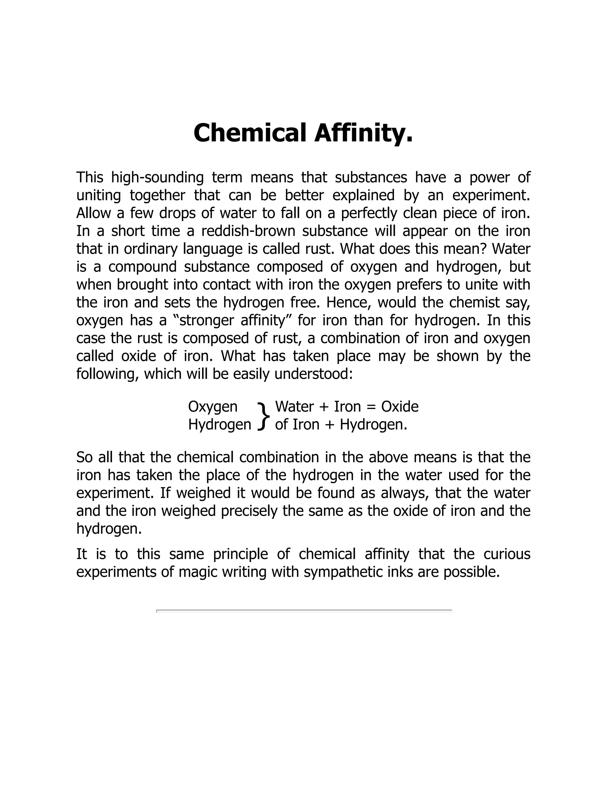
Chemical Affinity.
This high-soundingterm means that substances have a power of
uniting together that can be better explained by an experiment.
Allow a few drops of water to fall on a perfectly clean piece of iron.
In a short time a reddish-brown substance will appear on the iron
that in ordinary language is called rust. What does this mean? Water
is a compound substance composed of oxygen and hydrogen, but
when brought into contact with iron the oxygen prefers to unite with
the iron and sets the hydrogen free. Hence, would the chemist say,
oxygen has a “stronger affinity” for iron than for hydrogen. In this
case the rust is composed of rust, a combination of iron and oxygen
called oxide of iron. What has taken place may be shown by the
following, which will be easily understood:
Oxygen
Hydrogen } Water + Iron = Oxide
of Iron + Hydrogen.
So all that the chemical combination in the above means is that the
iron has taken the place of the hydrogen in the water used for the
experiment. If weighed it would be found as always, that the water
and the iron weighed precisely the same as the oxide of iron and the
hydrogen.
It is to this same principle of chemical affinity that the curious
experiments of magic writing with sympathetic inks are possible.
67.
Sympathetic Inks.
By meansof these may be carried on a correspondence which is
beyond the discovery of all not in the secret. With one class of these
inks the writing becomes visible only when moistened with a
particular solution. Thus, if we write to you with a solution of
sulphate of iron the letters are invisible. On the receipt of our letter,
you rub over the sheet a feather or sponge, wet with a solution of
nut-galls, and the letters burst forth into sensible being at once, and
are permanent.
2. If we write with a solution of sugar of lead and you moisten with
a sponge or pencil dipped in water impregnated with sulphuretted
hydrogen, the letters will appear with metallic brilliancy.
3. If we write with a weak solution of sulphate of copper, and you
apply ammonia, the letters assume a beautiful blue. When the
ammonia evaporates as it does on exposure to the sun or fire, the
writing disappears, but may be revived again as before.
4. If you write with oil of vitriol very much diluted, so as to prevent
its destroying the paper, the manuscript will be invisible except when
held to the fire, when the letters will appear black.
5. Write with cobalt dissolved in diluted muriatic acid; the letters will
be invisible when cold, but when warmed they will appear a bluish
green.
Secrets thus written will not be brought to the knowledge of a
stranger, because he does not know the solution which was used in
writing, and therefore knows not what to apply to bring out the
letters.
Other forms of elective affinity produce equally novel results. Thus,
two invisible gases, when combined, form sometimes a visible solid.
68.
Muriatic acid andammonia are examples, also ammonia and
carbonic acid.
On the other hand, if a solution of sulphate of soda be mixed with a
solution of muriate of lime the whole becomes solid.
Some gases when united form liquids, as oxygen and hydrogen,
which unite and form water. Some solids when combined form
liquids.
Chemical affinity is sometimes called elective, or the effect of choice,
as if one substance exerted a kind of preference for another, and
chose to be united to it rather than to that with which it was
previously combined; thus, if you pour some vinegar, which is a
weak acetic acid, upon some pearlash (a combination of potash and
carbonic acid), or some carbonate of soda (a combination of the
same acid with soda), a violent effervescence will take place,
occasioned by the escape of the carbonic acid, displaced in
consequence of the potash or soda preferring the acetic acid, and
forming a compound called an acetate.
Then, if some sulphuric acid be poured on this new compound, the
acetic acid will, in its turn, be displaced by the greater attachment of
either of the bases, as they are termed, for the sulphuric acid. Again,
if into a solution of blue vitriol (a combination of sulphuric acid with
copper), the bright blade of a knife be introduced, the knife will
speedily be covered with a coat of copper, deposited in consequence
of the acid preferring the iron of which the knife is made, a quantity
of it being dissolved in exact proportion to the quantity of copper
deposited.
It is on the same principle that a very beautiful preparation called a
silver-tree, or a lead-tree, may be formed, thus: Fill a wide bottle,
capable of holding from half a pint to a pint, with a tolerably strong
solution of nitrate of silver (lunar caustic), or acetate of lead, in pure
69.
distilled water. Thenattach a small piece of zinc by a string to the
cork or stopper of the bottle, so that the zinc shall hang about the
middle of the bottle, and set it by where it may be quite
undisturbed. In a short time brilliant plates of silver or lead, as the
case may be, will be seen to collect around the piece of zinc,
assuming more or less of the crystalline form. This is a case of
elective affinity; the acid with which the silver or lead was united
prefers the zinc to either of those metals, and in consequence
discards them in order to attach the zinc to itself; and this process
will continue until the whole of the zinc is taken up, or the whole of
the silver or lead deposited.
70.
Alum Baskets.
Form asmall basket about the size of the hand, of iron wire or split
willow; then take some cotton, such as ladies use for running into
flounces; untwist it and wind it round every limb of the basket. Boil
eighteen ounces of alum in a quart of water, or quantities in that
proportion; stir the mixture while boiling until the alum is completely
dissolved. Pour the solution into a deep pan, or other convenient
vessel, and suspend the basket in the liquor, so that no part of the
basket shall touch the vessel, or be exposed to the air. Let the whole
remain perfectly at rest for twenty-four hours. When you then
remove the basket the alum will be found very prettily crystallized
over all the limbs of the cottoned frame.
71.
Easy Crystallizations.
Saturate waterkept boiling with alum; then set the solution in a cool
place, suspending in it, by a hair, or fine silk thread, a cinder, a sprig
of a plant, or any other trifle. As the solution cools, a beautiful
crystallization of the salt takes place upon the cinders, etc., which
are made to resemble specimens of mineralogical spars.
72.
To Make aPiece of Charcoal Appear
as Though it were Coated with Gold.
Dilute a saturated solution of chloride of gold with five times its bulk
of water; place a thin strip of fresh burned charcoal into it, and apply
heat, gradually increasing it until the solution gently boils. The heat
will make the charcoal precipitate the metal on the charcoal, in the
form of brilliant spangles.
73.
To Give aPiece of Charcoal a Rich
Coat of Silver.
Lay a crystal of nitrate of silver upon a piece of burning charcoal; the
metallic salt will catch fire, and throw out the most beautiful
scintillations that can be imagined. The silver is reduced, and, in the
end, produces upon the charcoal a very brilliant appearance.
Many animal and vegetable substances, consist, for the most part, of
carbon, or charcoal, united with oxygen and hydrogen, which
remember, together combined, form water. Now oil of vitriol or
strong sulphuric acid, has so powerful an affinity or so great a thirst
for water, that it will abstract it from almost any body in which it
exists. If you pour some of this acid on a lump of sugar, or place a
chip of wood in a small quantity of it, the sugar or wood will become
speedily blackened, that is charred, in consequence of the oxygen
and hydrogen being removed by the sulphuric acid, and only the
carbon or charcoal left.
When Cleopatra dissolved pearls of wondrous value in vinegar, she
was unwittingly giving an example of chemical affinity. The pearl is
simply carbonate of lime stored up by the oyster in layers.
Consequently the precious jewels were decomposed by the greater
affinity or fondness of lime for the acetic acid in the vinegar, than for
the carbonic acid with which it had been before united. This was an
example of inconstancy in strong contrast with the conduct of their
owner, who chose death rather than become the wife of her lover’s
conqueror.
74.
Combustion.
It is necessaryto distinguish between burning and the mere
appearance of it. A gas flame is gas in a state of combustion,
whereas the electric light is no example of it, although the wire
within the glassen cylinder is red hot, and to all appearance burning.
Combustion generally takes place through the strong affinity of some
element, such as carbon in a substance for the oxygen in the
atmosphere. In coal gas, for instance, the carbon contained in it
unites with the oxygen in the air to form a colorless substance called
carbonic acid gas. The latter is unable to support life, and may be
called, therefore, poisonous. It is the presence of this gas which
makes it unhealthy to burn many jets without proper ventilation.
Also, carbonic acid gas is given off by the lungs. It may seem
curious, but it is none the less true, that breathing is a process of
combustion. The blood brings to the surface of the lungs the carbon,
which has resulted from the waste of the internal organs of the
body. When drawing in a breath the oxygen present in the
atmosphere meets the impure blood at the surface of the lungs, and
purifies it by uniting with the carbon in it. Then, though oxygen has
been breathed in, carbonic acid gas has been breathed out.
To prove this will be interesting: Obtain from a chemist a little lime
water—two cents worth will do. It looks like ordinary water, being
perfectly transparent and colorless. Pour some into a clean glass,
and through a glass tube blow steadily into the water. In half a
minute the hitherto colorless liquid will become milky and opaque. If
allowed to stand there will fall down at the bottom of the glass a
white powder.
What has happened in this case? The carbonic acid gas from the
lungs has formed with the lime in the lime water a substance called
75.
carbonate of lime,which, being insoluble in water, falls to the
bottom of the glass as a white powder.
If carbonic acid gas were not present in the air blown from the
lungs, this milkiness would not appear, for no other gas, except this,
would alter the lime water’s clearness.
76.
Chemistry of TheAir.
Before proceeding further, it will be well to perform one or two
experiments, to prove that the air we breathe is by no means the
simple substance it is generally supposed to be. Although it is
invisible, it must be remembered that it presses with a force of over
fifteen pounds to the square inch, over the whole surface of the
earth. It extends, too, to a height of some forty miles above the
earth, and though it cannot be seen, it can be felt in the rush of the
hurricane, and heard in the roar of the tempest. It is chiefly
composed of a mixture of two gases, oxygen and nitrogen.
Did the air consist entirely of the former, people would breathe too
quickly, and die in a very short time in a high fever, burned up, in
fact. If only consisting of nitrogen, the human race would also die,
because this element is incapable of supporting life; people would be
suffocated, in fact.
Therefore, a judicious mixture of the two is essential to the life of
animals. Generally, in a hundred parts of air by weight there are
seventy-six parts of nitrogen to twenty-three of oxygen.
Besides these two gases, there is also a quantity of carbonic acid
gas in the air, given off by all the fires and animals in the world. Of
course, its amount is much greater in the great towns and
manufacturing centers than in country districts.
Now herein must be recorded one of these charming arrangements
which Nature has designed for the benefit of her children. Carbonic
acid gas is much heavier than the air, and, therefore, sinks towards
the ground, where, if allowed to accumulate, would cause the death
of every animal. Fortunately, however, plants breathe in through
their leaves carbonic acid gas during sunshine, and break it up into
carbon and oxygen. The former, they use for building up their
77.
trunks, leaves, andflowers, while during the night they give off
oxygen into the air.
This is the reason why plants and trees planted in the streets so
largely help to sweeten and purify the foul air of a great city.
An experiment to prove that the atmosphere does consist of
nitrogen and oxygen, may be prettily proved in the following simple
manner: A glass marmalade jar, or a soup-plate filled with water, and
a piece of phosphorus as large as a pea, are the only things
necessary. Take very great care not to touch the phosphorus, for the
heat of the hand is sufficient to set it on fire, and a terrible wound
would be caused.
Place the phosphorus in a match-box on the surface of the water,
touch it with a lighted match, and put the jar-mouth downwards
over it to the bottom of the plate. The phosphorus burns with a
dazzling brilliancy, and gives off dense white fumes. At the same
time the water rises a third of the way up the jar, but not to the top,
thus showing that all the invisible matter has not been consumed.
The white soon settles into the water and is dissolved. The
phosphorus has combined with the oxygen in the jar and forms
phosphoric oxide, which dissolves in water. There is then only the
nitrogen left. The disappearance of the oxygen allows the water to
fill up the space it formerly occupied.
This may be followed by another experiment.
To show that oxygen is necessary for the support of combustion, fix
two or three pieces of wax taper on flat pieces of cork, and set them
floating on water in a soup-plate, light them, and invert over them a
glass jar.
As they burn, the heat produced may perhaps at first expand the air,
so as to force a small quantity out of the jar, but the water will soon
rise in the jar, and continue to do so until the tapers expire, when
78.
you will findthat a considerable portion of the air has disappeared,
and what remains will no longer support flame.
The oxygen has been converted partly into water, and partly into
carbonic acid gas, by uniting with the carbon and hydrogen of which
the taper consists, and the remaining air is principally nitrogen, with
some carbonic acid. The presence of the latter may be proved by
decanting some of the remaining air into a bottle, and then shaking
some lime water with it, which will absorb the carbonic acid and
form chalk.
Into an ale glass, two thirds full of water at about 140 degrees, drop
one or two pieces of phosphorus about the size of peas, and they
will remain unaltered. Then take a bladder containing oxygen gas, to
which is attached a stop cock and a long fine tube. Pass the end of
the tube to the bottom of the water, turn the stop cock, and press
the bladder gently. As the gas reaches the phosphorus it will take
fire, and burn under the water with a brilliant flame, filling the glass
with brilliant flashes of light dashing through the water.
Into another glass put some cold water; introduce carefully some of
the salt called chlorate of potash; upon that drop a piece of
phosphorus; then let some strong sulphuric acid (oil of vitriol) trickle
slowly down the side of the glass, or introduce it by means of a
dropping bottle.
As soon as the acid touches the salt the latter is decomposed, and
liberates a gas which ignites the phosphorus, producing much the
same appearance as in the last experiment.
Into the half of a broken phial put some chlorate of potash, and pour
in some oil of vitriol. The phial will soon be filled with a heavy gas of
a deep yellow color. Tie a small test tube at right angles to the end
of a stick not less than a yard long, put a little ether into the tube,
and pour it gently into the phial of gas, when an instantaneous
explosion will take place, and the ether will be set on fire. This
experiment should be performed in a place where there are no
articles of furniture to be damaged, as the ingredients are often
79.
scattered by theexplosion, and the oil of vitriol destroys all animal
and vegetable substances.
Into a jar containing oxygen gas introduce a coil of soft iron wire,
suspended to a cork that fits the neck of the jar and having attached
a small piece of charcoal to the lower part of the wire, ignite the
charcoal. The iron will take fire and burn with a brilliant light,
throwing out bright scintillations, which are oxide of iron, formed by
the union of the gas with the iron; and they are so intensely hot that
some of them will probably melt their way into the sides of the jar, if
not through them.
But by far the most intense heat, and most brilliant light, may be
produced by introducing a piece of phosphorus into a jar of oxygen.
The phosphorus may be placed in a small copper cup, with a long
handle of thick wire passing through a hole in a cork that fits the jar.
The phosphorus must first be ignited; and as soon as it is introduced
into the oxygen, it gives out a light so brilliant that no eye can bear
it, and the whole jar appears filled with an intensely luminous
atmosphere. It is well to dilute the oxygen with about one-fourth
part of common air, to moderate the intense heat, which is nearly
certain to break the jar if pure oxygen is used.
The following experiment shows the production of heat by chemical
action alone: Bruise some fresh-prepared crystals of nitrate of
copper, spread them over a piece of tin foil, sprinkle them with a
little water; then fold up the foil tightly, as rapidly as possible, and in
a minute or two it will become red hot, the tin apparently burning
away. This heat is produced by the energetic action of the tin on the
nitrate of copper, taking away its oxygen in order to unite with the
nitric acid, for which, as well as for the oxygen the tin has a much
greater affinity than the copper has.
80.
Combustion without flamemay be shown in a very elegant and
agreeable manner, by taking a coil of platinum wire and twisting it
round the stem of a tobacco pipe, or any cylindrical body for a dozen
times or so, leaving about an inch straight, which should be inserted
into the wick of a spirit lamp. Light the lamp, and after it has burned
for a minute or two, extinguish the flame quickly; the wire will soon
become red hot, and, if kept from draughts of air, will continue to
burn until all the spirit is consumed.
Spongy platinum, as it is called, answers rather better than wire, and
has been employed in the formation of fumigators for the drawing-
room, in which, instead of pure spirit, some perfume, such as
lavender water, is used; by its combustion an agreeable odor is
diffused through the apartment. These little lamps were much in
vogue a few years ago, but are now nearly out of fashion. Finally, all
the readers of this little book should be very careful in performing all
experiments. If possible, he should use a room with a stone floor
and no curtains, while an outhouse with an earthen floor is still less
dangerous.
81.
Amateur Air Pump.
Amost interesting class of experiments can be made with an air
pump, a piece of apparatus unfortunately beyond the pocket-money
supply of the average boy. Nevertheless, if the following instructions
are exactly followed and carefully carried out, a very excellent air
pump can be made at a comparatively small cost. Some pretty, as
well as interesting results will amply repay you for the trouble you
take to make the pump. Although the air seems so light in
comparison with water or a heavy metal like iron, you must
remember that it really presses upon every square inch of the earth’s
surface, aye, on every square inch of your own bodies, with a force
of fourteen and a half pounds. In other words, the weight of the air
at the sea level resting on each square inch of surface weighs
fourteen and a half pounds.
Don’t be frightened, boys, at the explanation of one word that must
be used in connection with air experiments. The word is vacuum.
Vacuum really means an empty space, devoid of all matter, even of
air. Although it seems easy to think of an empty space, it is quite
impossible to exhaust a space of all matter, even of air. For this
reason, the alchemists of the middle ages used to say: “Nature
abhors a vacuum.” This was only their way of saying how impossible
it was to make a space, such as the inside of a vessel, quite empty.
Yet it is possible to reduce the amount of air in a vessel almost to
nothing.
82.
Fig. 1. Fig.2.
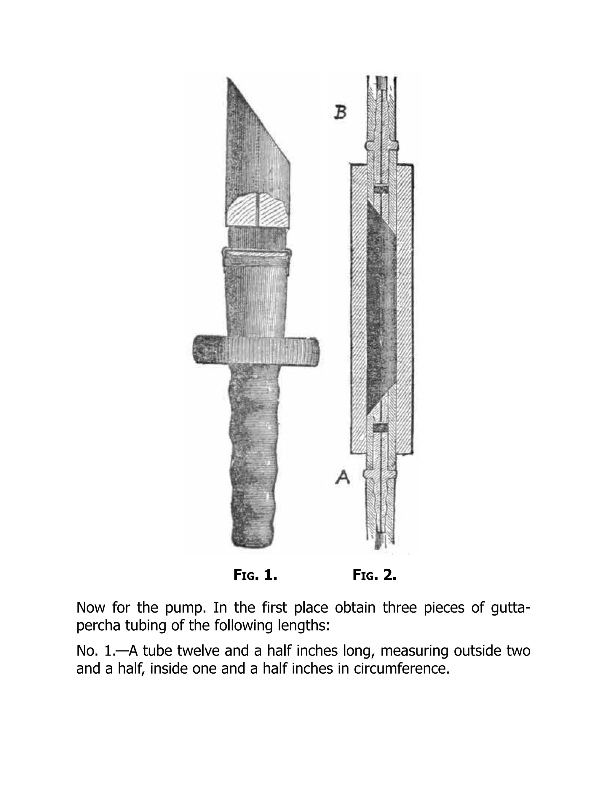
Now for the pump. In the first place obtain three pieces of gutta-
percha tubing of the following lengths:
No. 1.—A tube twelve and a half inches long, measuring outside two
and a half, inside one and a half inches in circumference.
83.
No. 2.—This mustbe seven and a half inches long, one and a half
inches outside, and an inch inside.
No. 3.—This is a length of tubing about sixty inches long, two and a
half inches in outside circumference, and at least an inch thick. If an
inch and a half thick all the better, as it will be more air-tight.
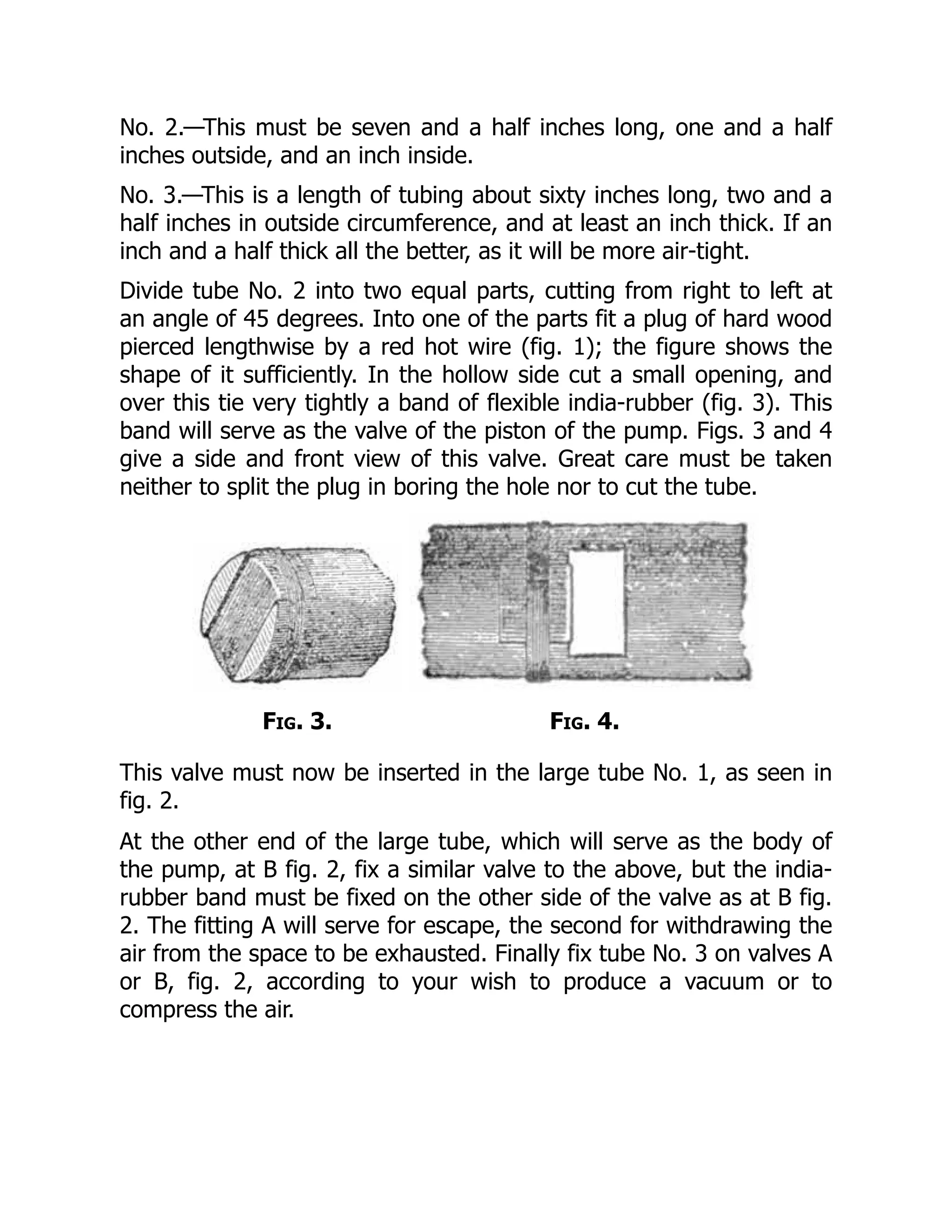
Divide tube No. 2 into two equal parts, cutting from right to left at
an angle of 45 degrees. Into one of the parts fit a plug of hard wood
pierced lengthwise by a red hot wire (fig. 1); the figure shows the
shape of it sufficiently. In the hollow side cut a small opening, and
over this tie very tightly a band of flexible india-rubber (fig. 3). This
band will serve as the valve of the piston of the pump. Figs. 3 and 4
give a side and front view of this valve. Great care must be taken
neither to split the plug in boring the hole nor to cut the tube.
Fig. 3. Fig. 4.
This valve must now be inserted in the large tube No. 1, as seen in
fig. 2.
At the other end of the large tube, which will serve as the body of
the pump, at B fig. 2, fix a similar valve to the above, but the india-
rubber band must be fixed on the other side of the valve as at B fig.
2. The fitting A will serve for escape, the second for withdrawing the
air from the space to be exhausted. Finally fix tube No. 3 on valves A
or B, fig. 2, according to your wish to produce a vacuum or to
compress the air.
84.
Fig. 5.
By meansof a pedal made simply with two boards put together on
hinges (fig. 5), one pressed with the foot, the air contained in the
body of the pump (fig. 2) tends to escape. It therefore lifts the valve
of the fitting fixed at A, and escapes through the flexible elastic band
tied over the hole in the hollow side of tube No. 2. If the pressure
ceases the big tube, on account of its own elasticity, takes its former
form and sucks in the air. This time it is the valve at B which is lifted
and lets pass the air which fills the body of the pump. If one has
fixed on to the fitting at B, the long india-rubber tube No. 3, which is
plunged in a receiver—a receiver is any vessel in which the air is
exhausted, or into which it is forced—it is easily understood that
after a few moves of the pedal, the air is drawn out, and a vacuum
is obtained.
85.
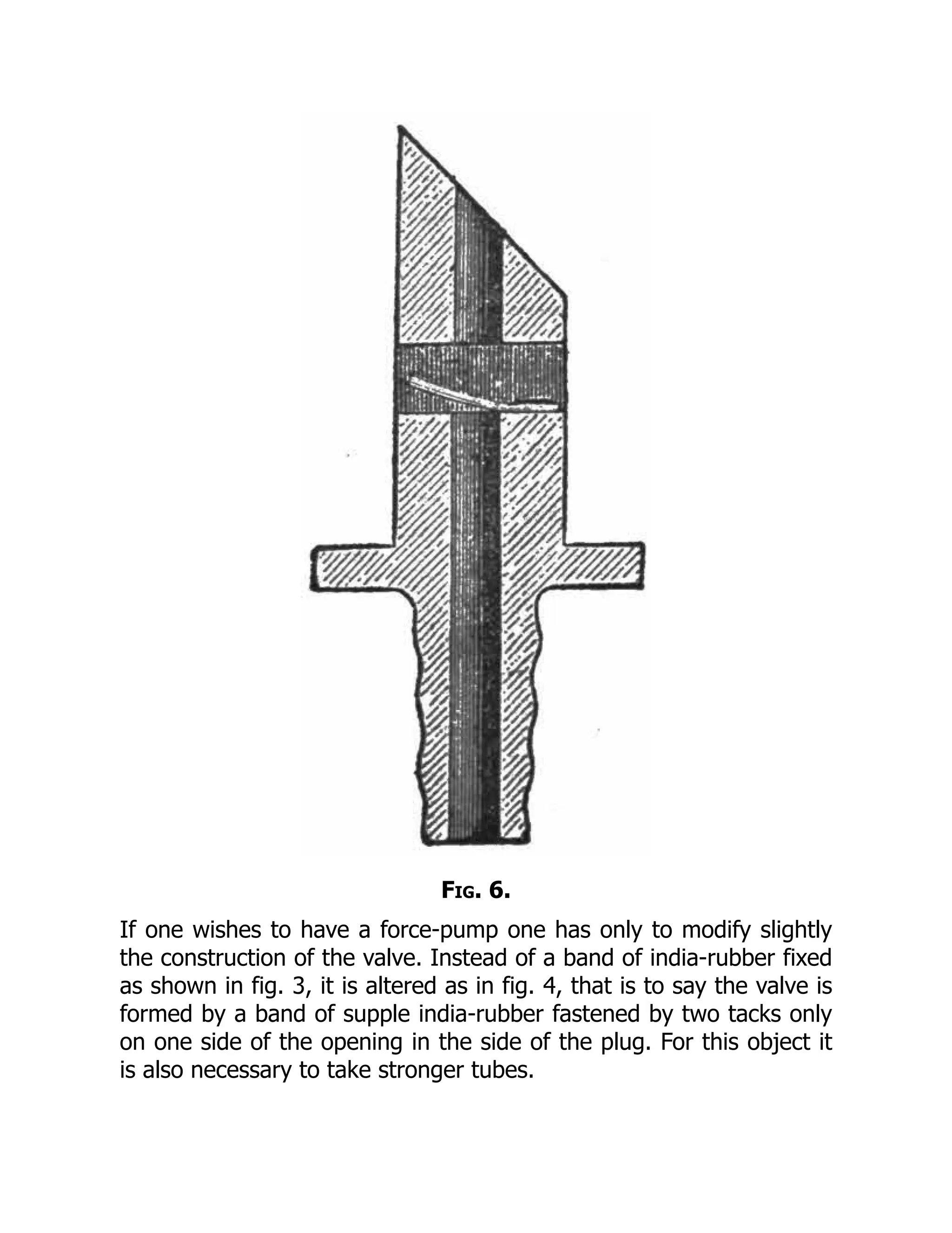
Fig. 6.
If onewishes to have a force-pump one has only to modify slightly
the construction of the valve. Instead of a band of india-rubber fixed
as shown in fig. 3, it is altered as in fig. 4, that is to say the valve is
formed by a band of supple india-rubber fastened by two tacks only
on one side of the opening in the side of the plug. For this object it
is also necessary to take stronger tubes.
86.
Welcome to ourwebsite – the perfect destination for book lovers and
knowledge seekers. We believe that every book holds a new world,
offering opportunities for learning, discovery, and personal growth.
That’s why we are dedicated to bringing you a diverse collection of
books, ranging from classic literature and specialized publications to
self-development guides and children's books.
More than just a book-buying platform, we strive to be a bridge
connecting you with timeless cultural and intellectual values. With an
elegant, user-friendly interface and a smart search system, you can
quickly find the books that best suit your interests. Additionally,
our special promotions and home delivery services help you save time
and fully enjoy the joy of reading.
Join us on a journey of knowledge exploration, passion nurturing, and
personal growth every day!
ebookbell.com


![Notation
I Real-valued, constant current
V Real-valued, constant voltage
R Resistance
i, i(t) Real-valued, time varying current
v, v(t) Real-valued, time varying voltage
−
→
I Phasor current (complex quantity)
−
→
V Phasor voltage (complex quantity)
−
→
Z Phasor impedance (complex quantity)
−
→
Y Phasor admittance (complex quantity)
a ∧ b Logical AND of a and b
a ∨ b Logical OR of a and b
x Largest integer less than or equal to x
x Smallest integer greater than or equal to x
j
√
−1
Equal to by definition
Convolution
[x1, x2] Closed interval, inclusive of x1 and x2
[x1, x2) Open interval, inclusive of x1 and exclusive of x2
(x1, x2) Open interval, exclusive of x1 and x2
Hz Frequency in Hertz
wrt With respect to
xv](https://image.slidesharecdn.com/23076224-250509193939-8c6bd658/75/Basic-Electronic-Circuits-Problems-And-Solutions-K-Vasudevan-15-2048.jpg)
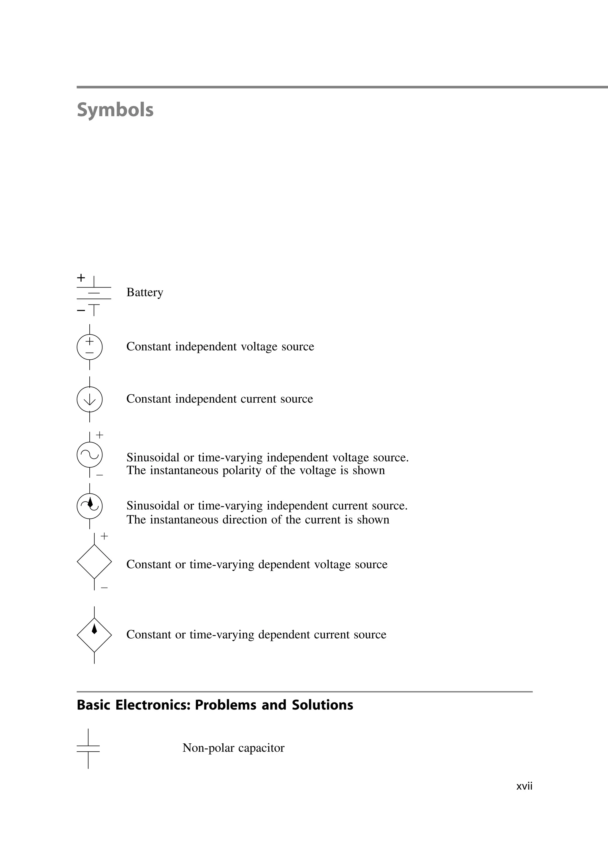
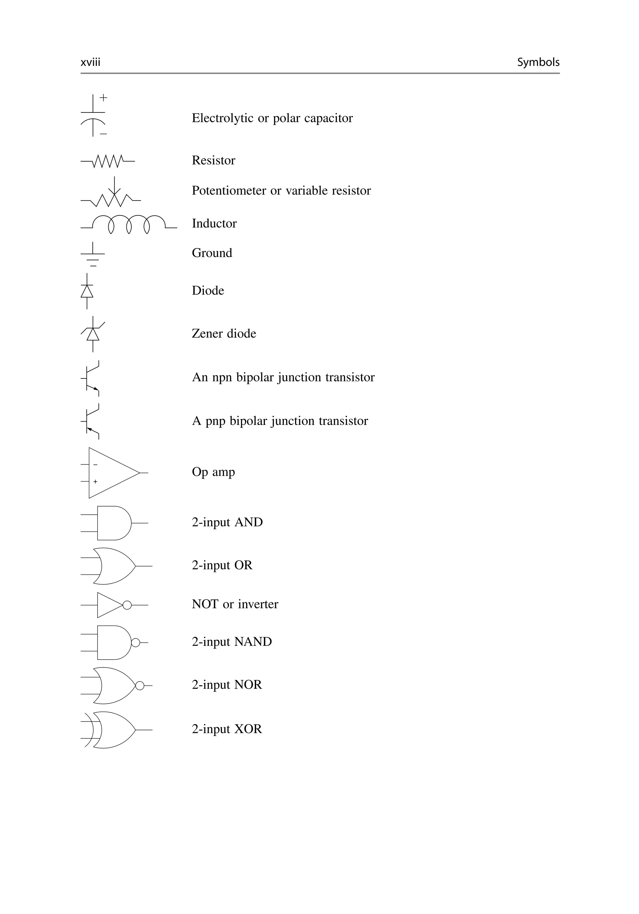
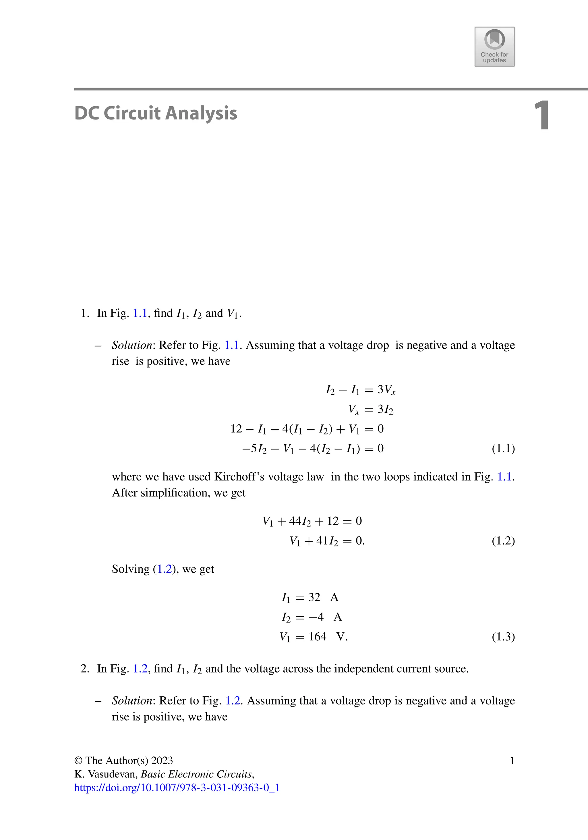
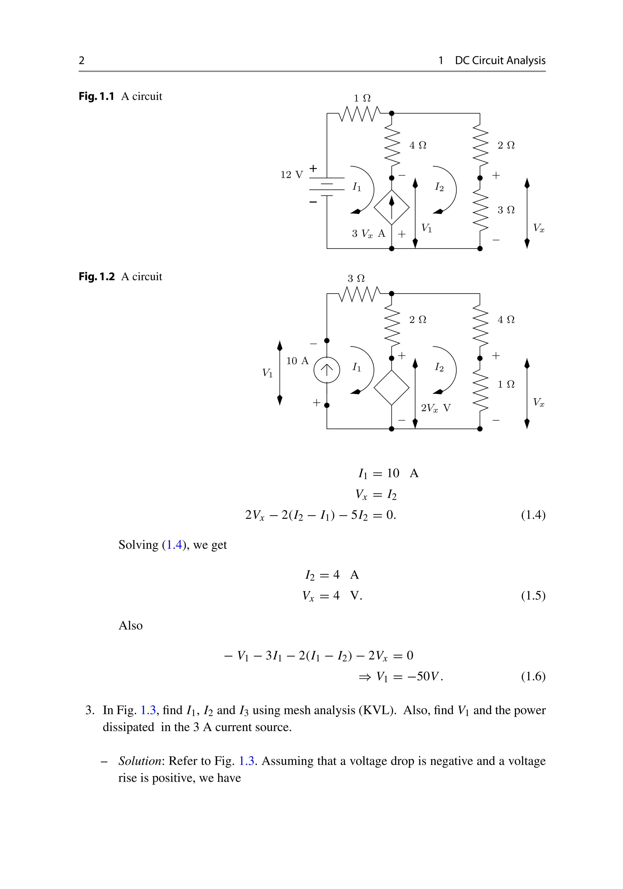
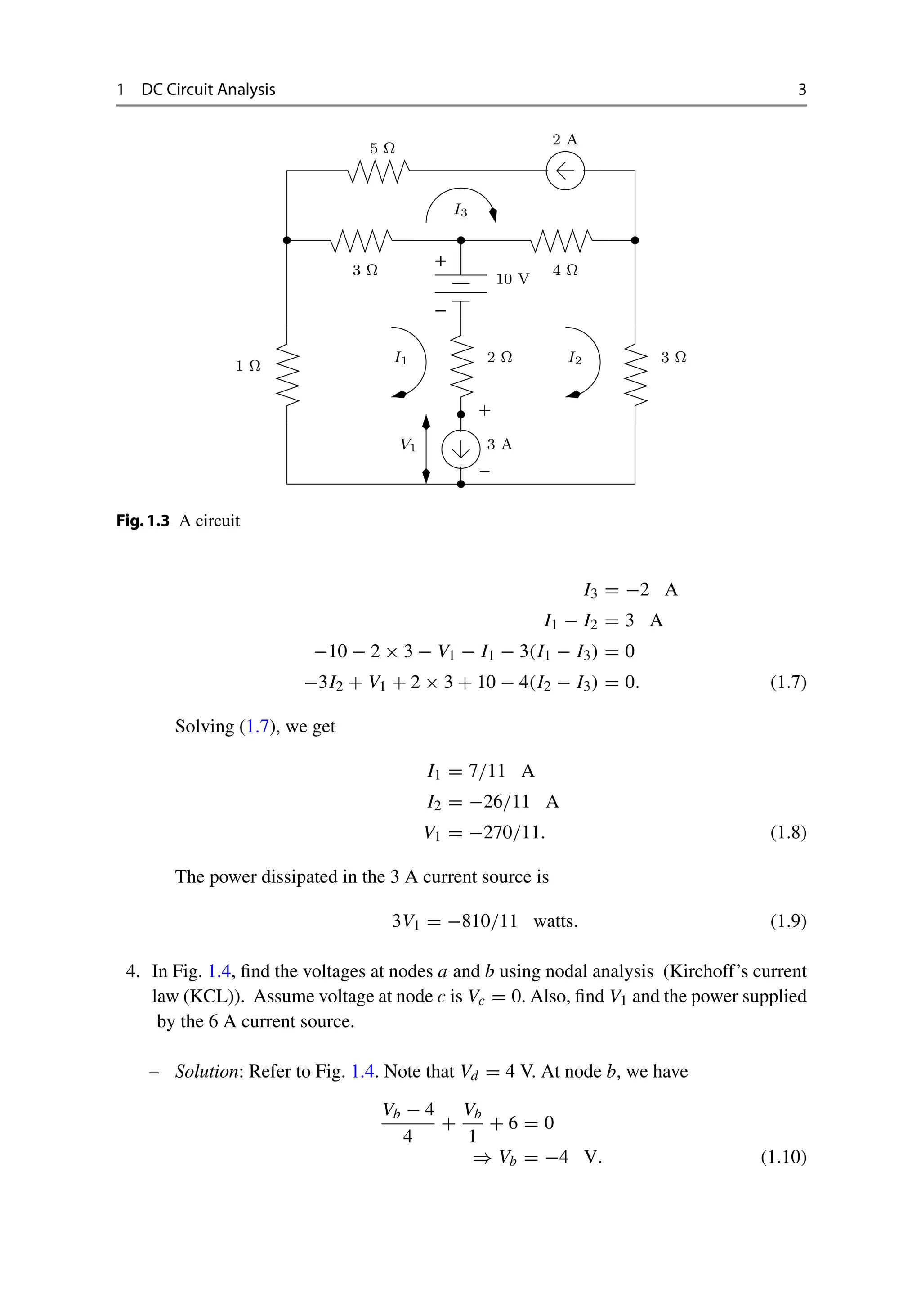
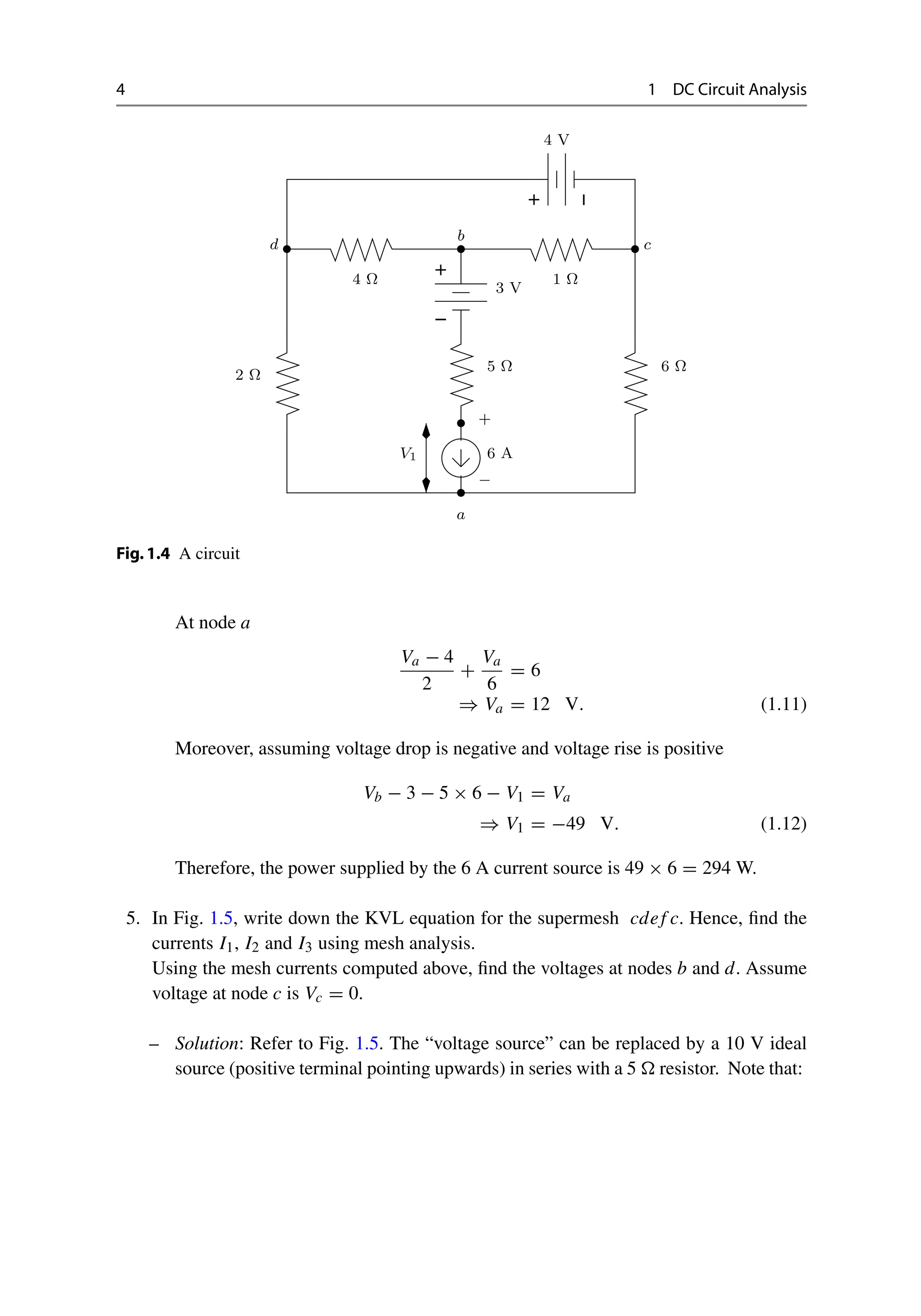
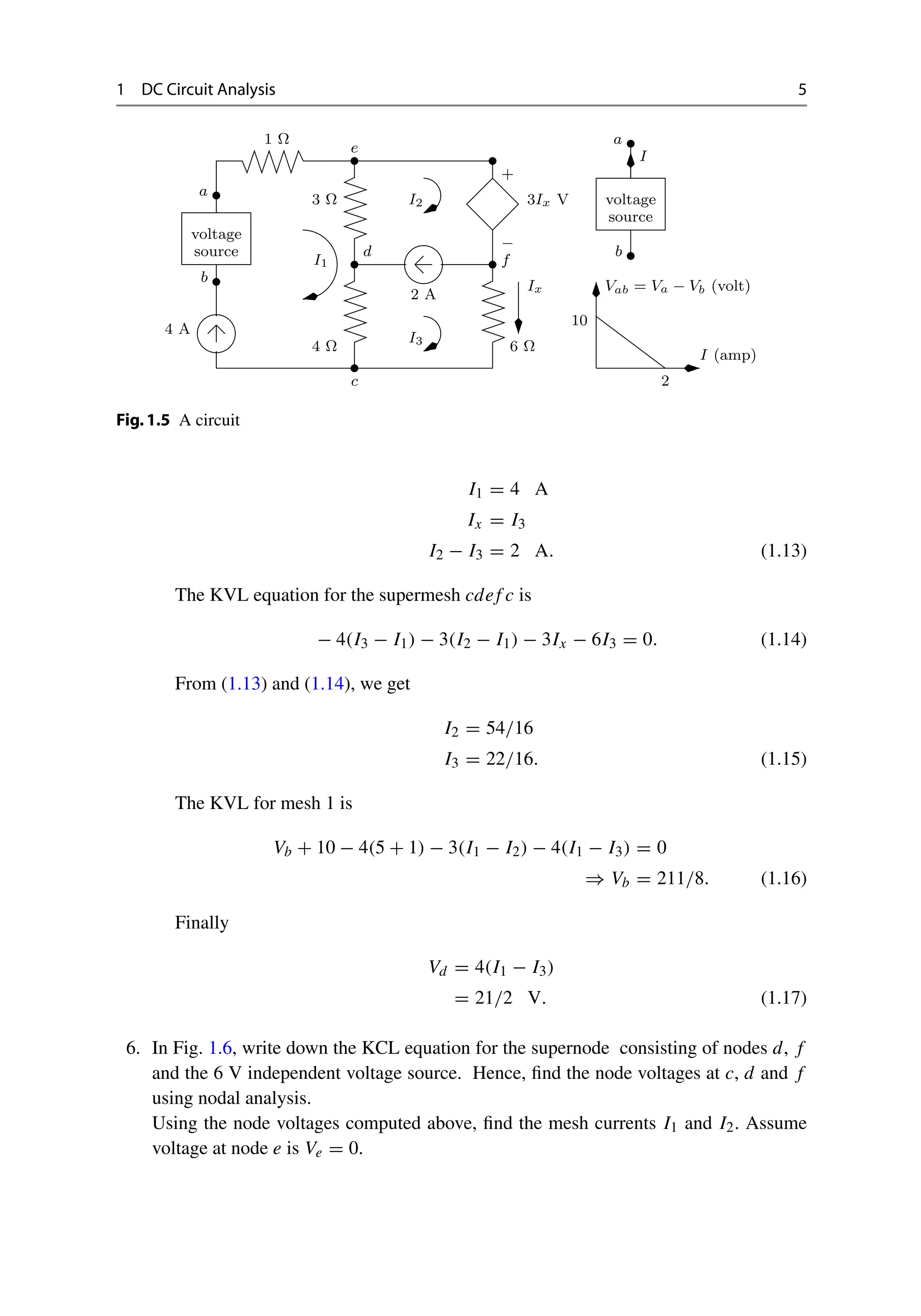
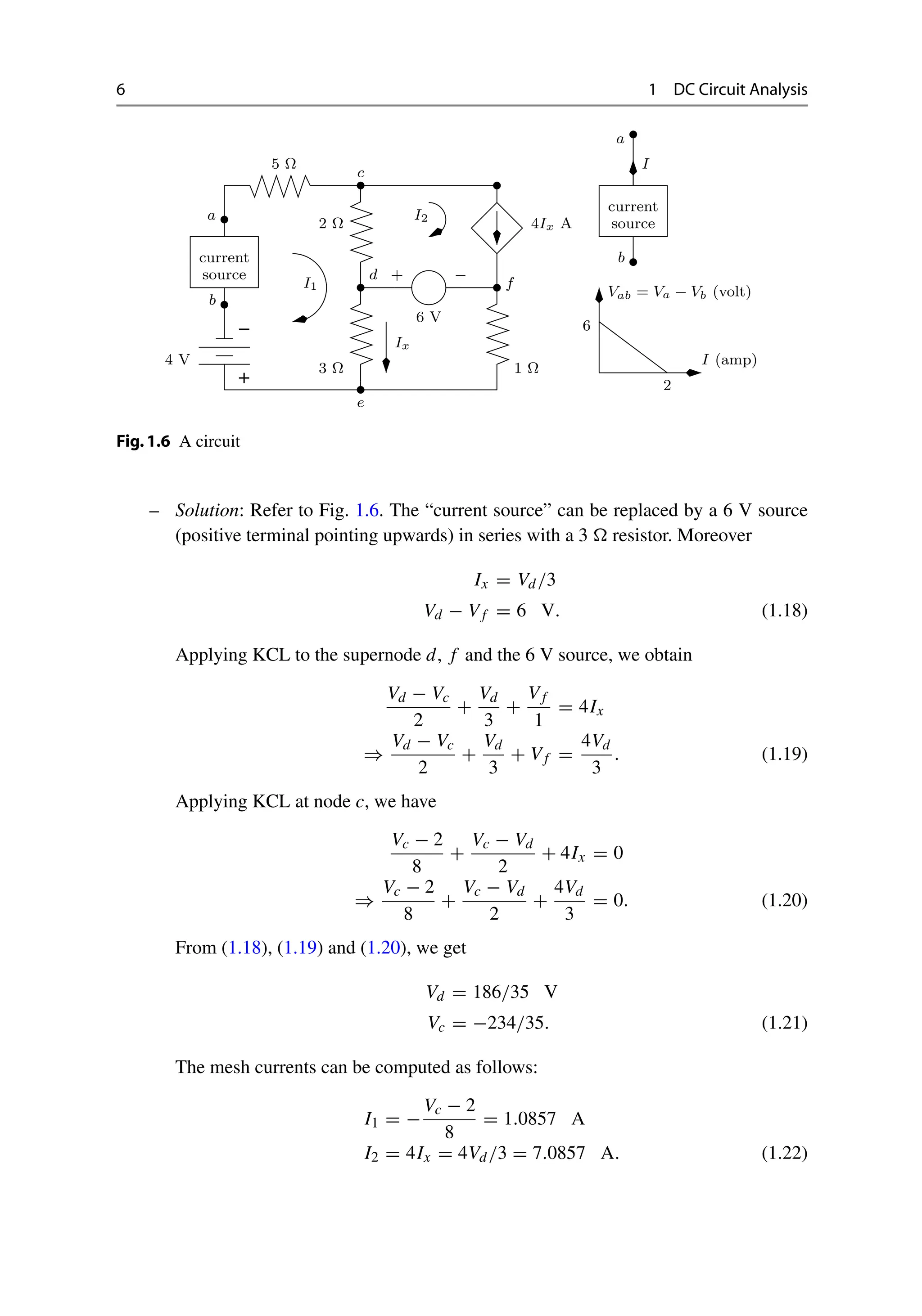
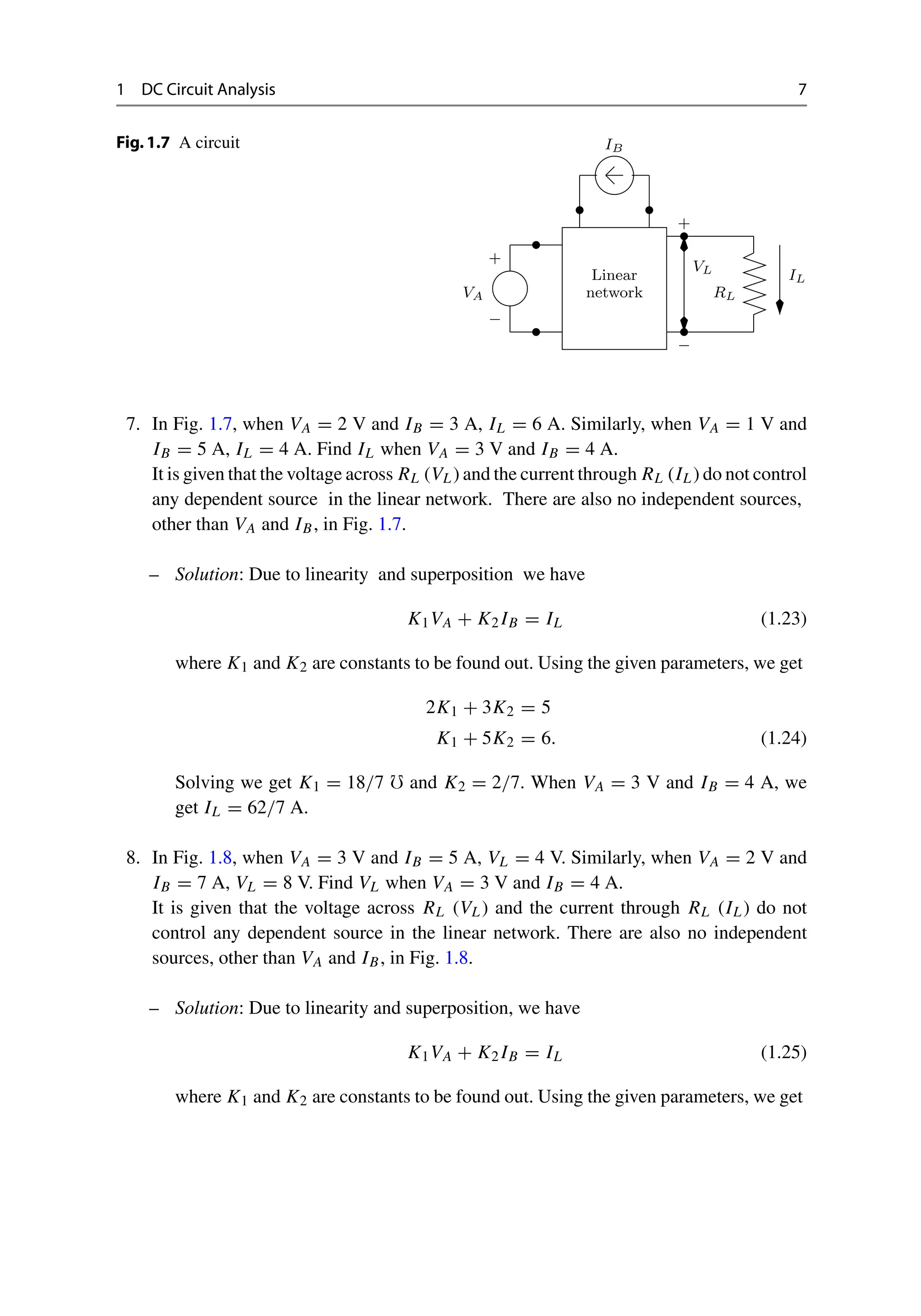
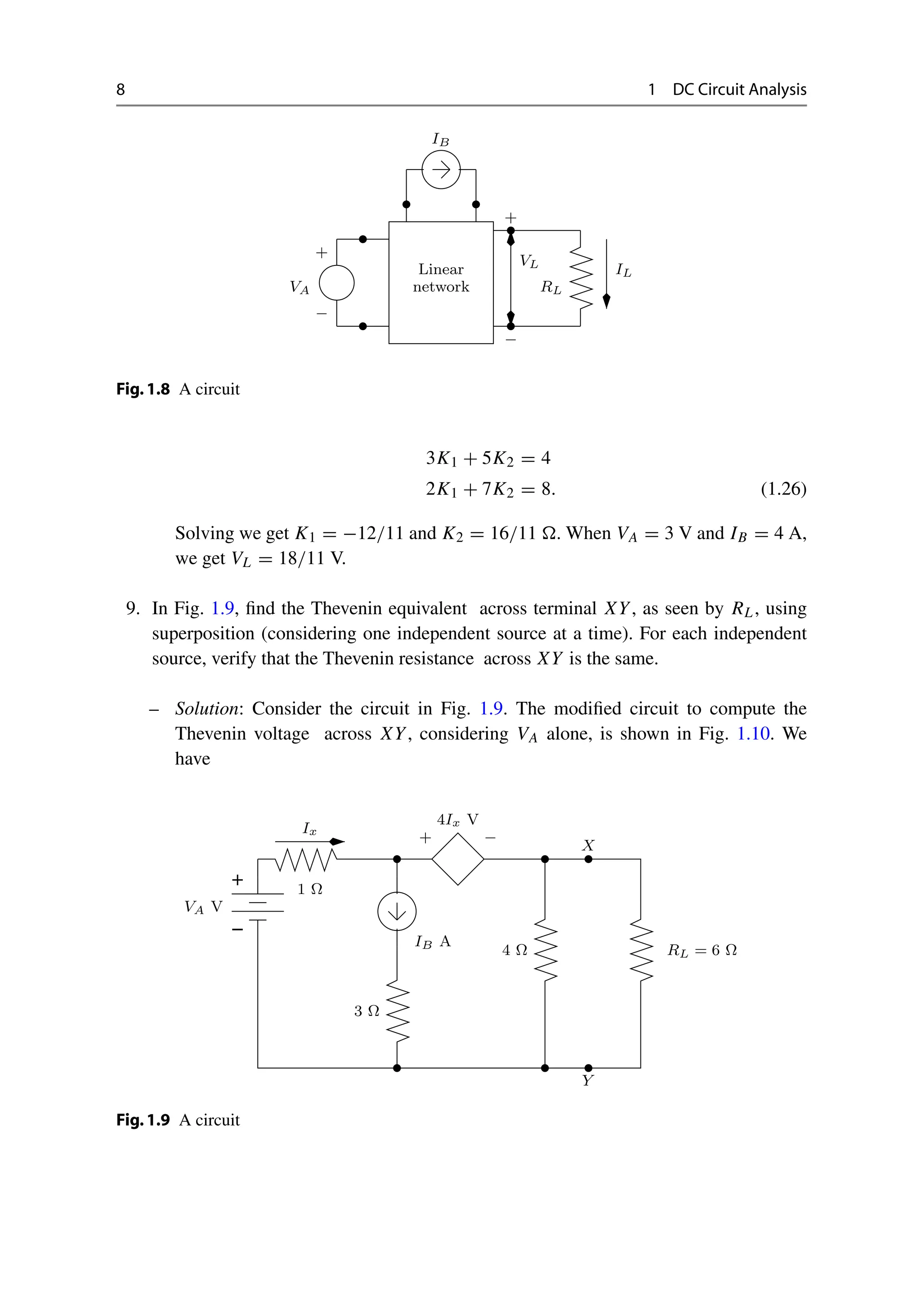
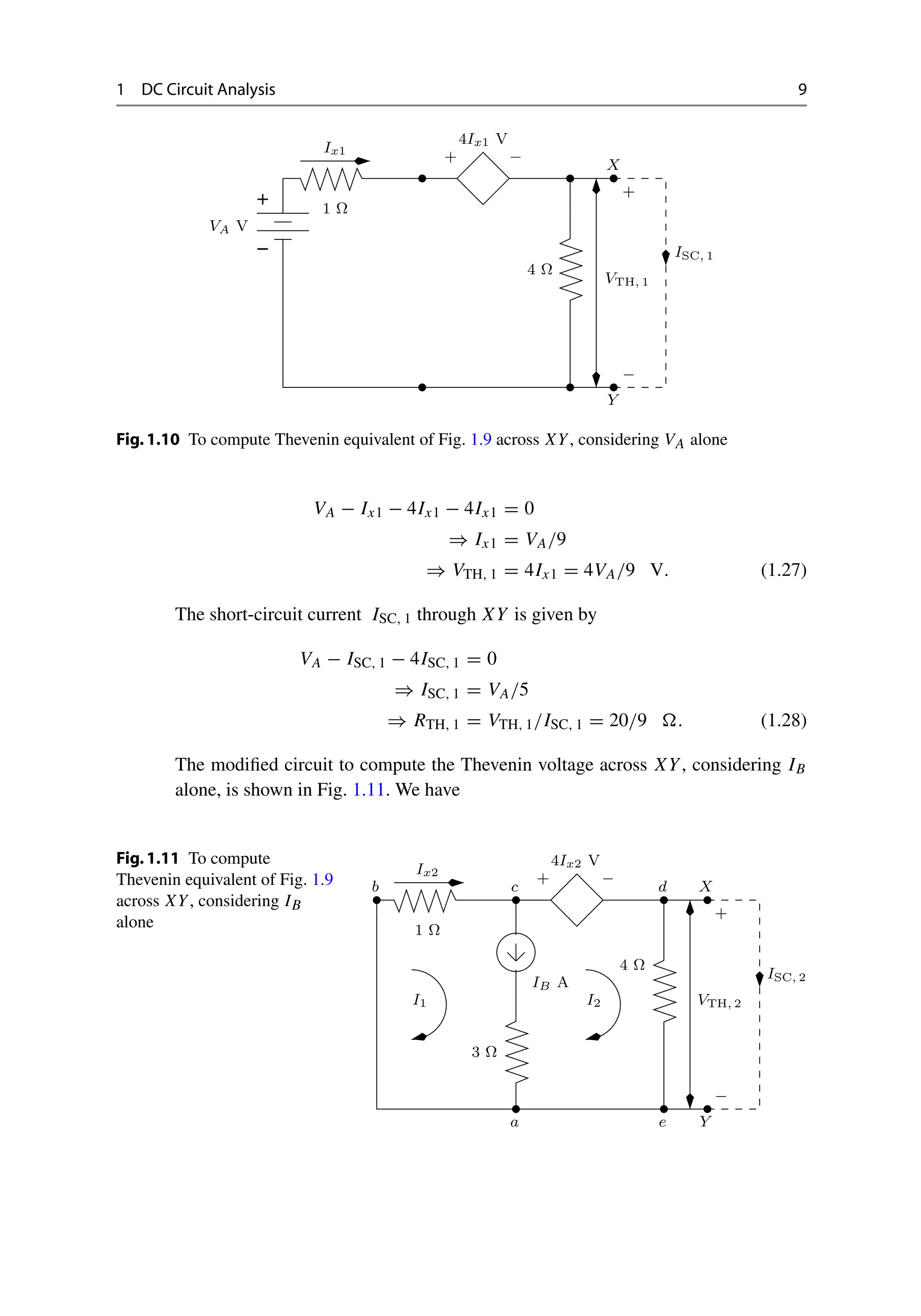
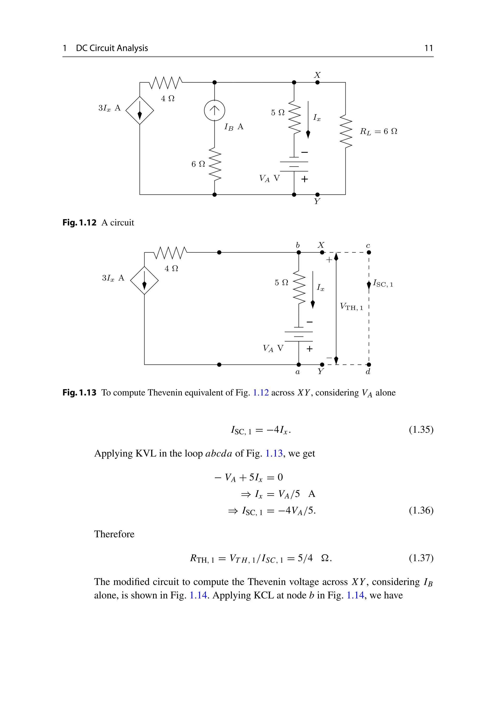

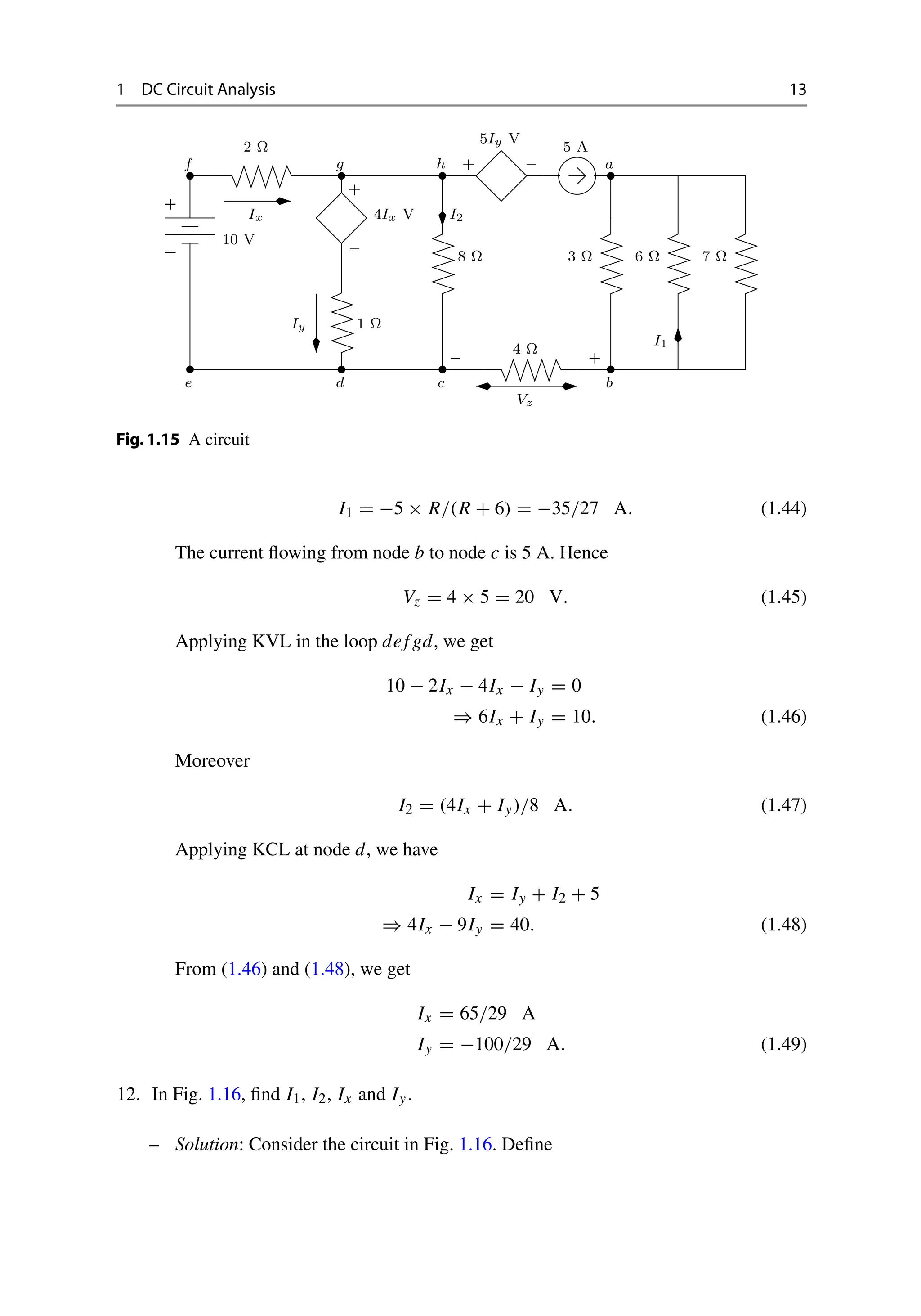
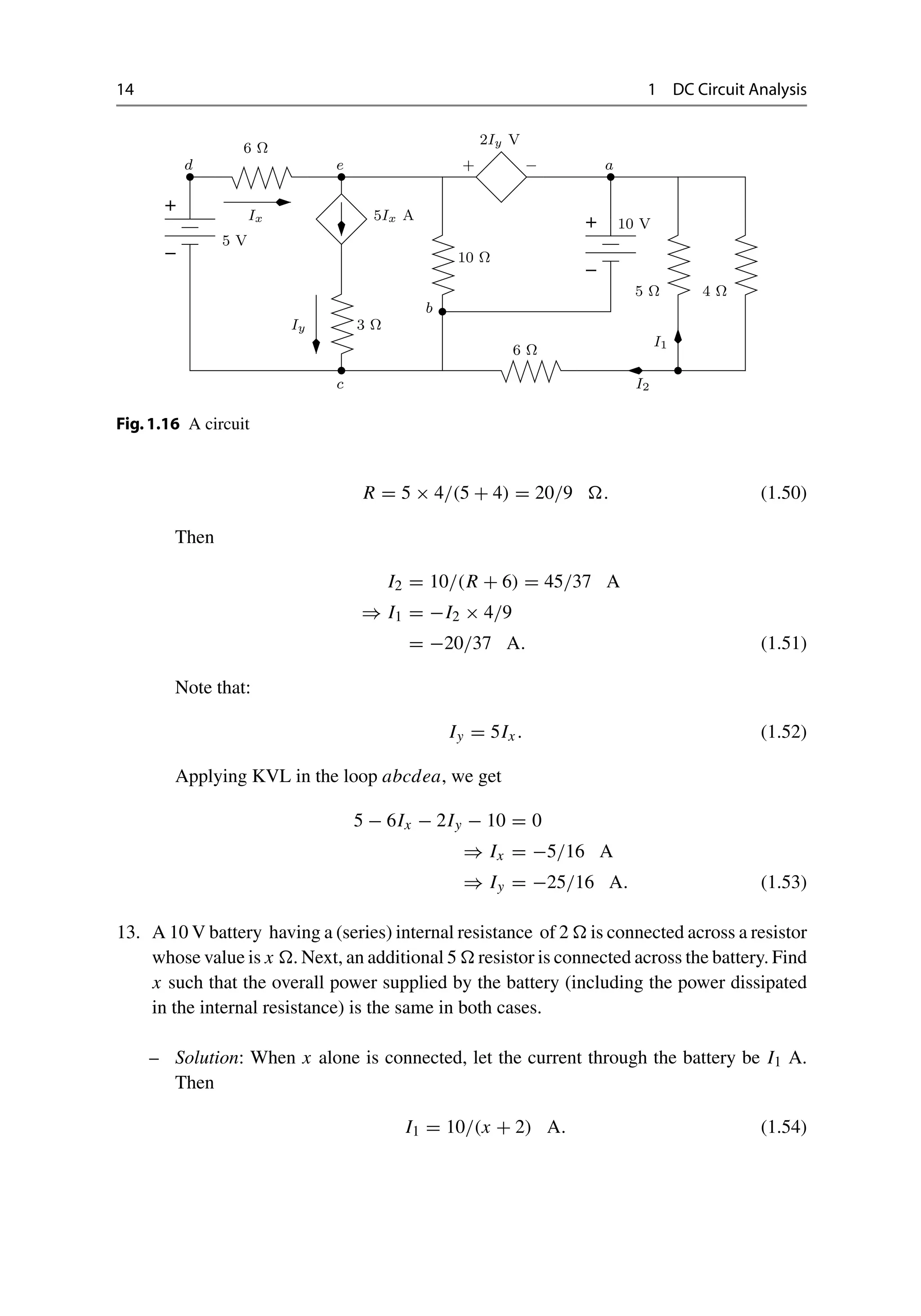
![16 1 DC Circuit Analysis
R1 = 2x/(2 + x) . (1.63)
The current through the internal resistance is
I1 = 10x/(2 + x) = 5R1. (1.64)
Hence, the overall power supplied by the current source is
P1 = 100R1 − 2I2
1 = 100R1 − 50R2
1. (1.65)
In the second case, the overall resistance is
R2 = 2(2 + x)/(4 + x) . (1.66)
The current through the internal resistance is
I2 = 10(2 + x)/(4 + x) = 5R2. (1.67)
Hence, the overall power supplied by the current source is
P2 = 100R2 − 2I2
2 = 100R2 − 50R2
2. (1.68)
Since
100R1 − 50R2
1 = 100R2 − 50R2
2
⇒ 50(R1 − R2)[2 − (R1 + R2)] = 0 (1.69)
we get two solutions. The first solution is
R1 = R2
⇒ x → ∞ (1.70)
which is a trivial solution. The second solution is
R1 + R2 = 2
⇒ x2
+ 2x − 4 = 0
⇒ x = (−2 ±
√
20)/2. (1.71)
Since x must be positive, we get
x = −1 +
√
5 . (1.72)
15. In Fig. 1.17, find I using KVL. Again, find I by applying Thevenin’s theorem across
terminals XY, as seen by RL.](https://image.slidesharecdn.com/23076224-250509193939-8c6bd658/75/Basic-Electronic-Circuits-Problems-And-Solutions-K-Vasudevan-33-2048.jpg)


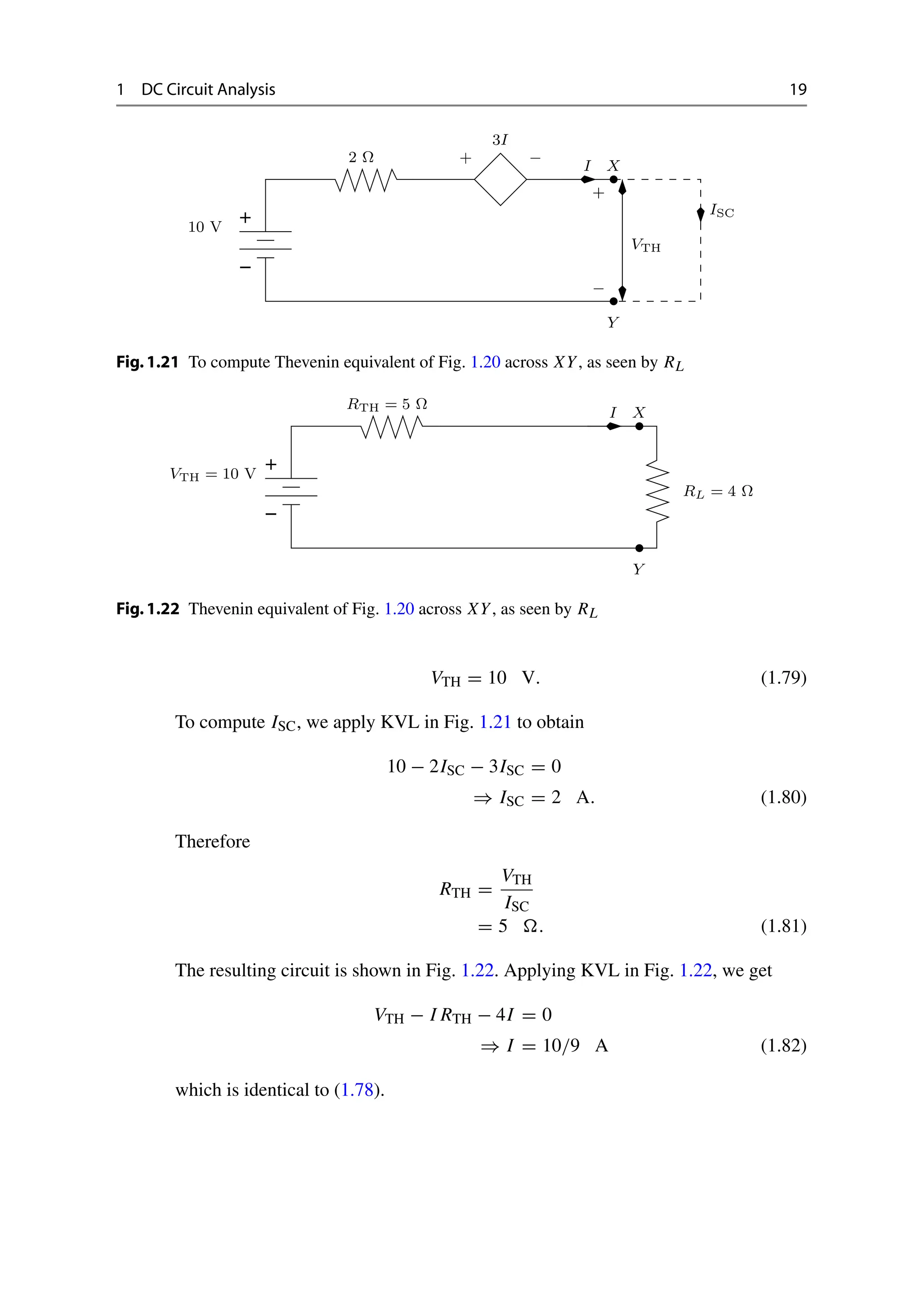
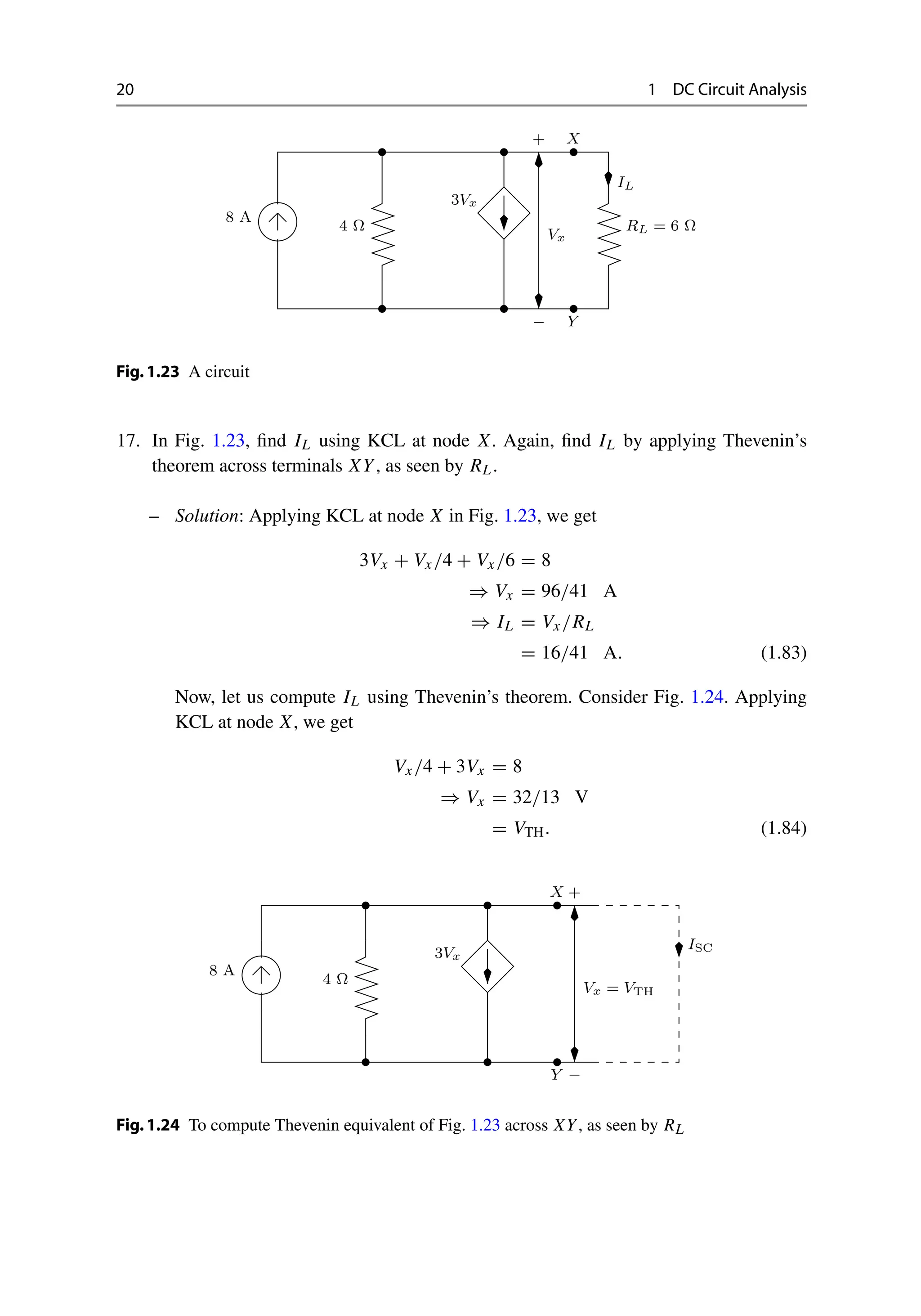
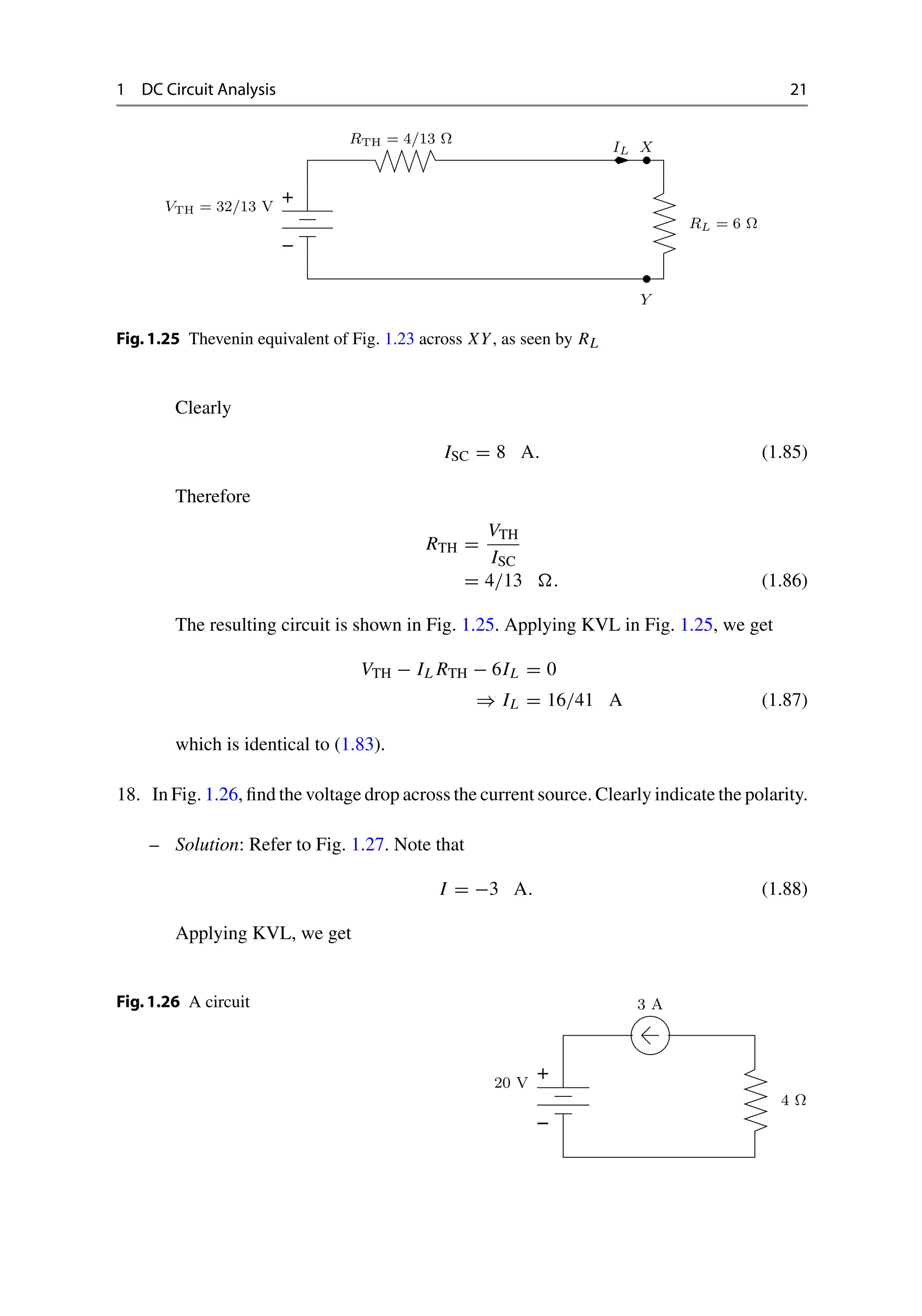
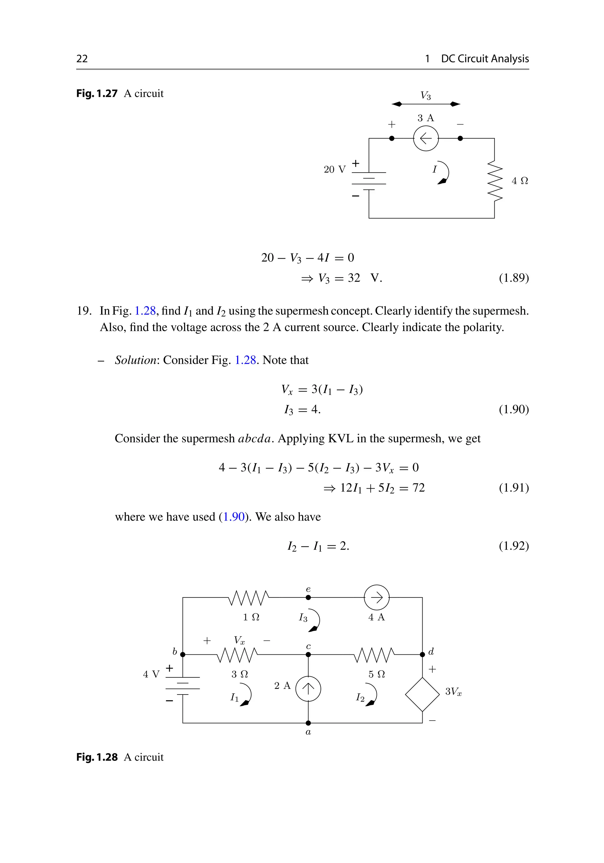
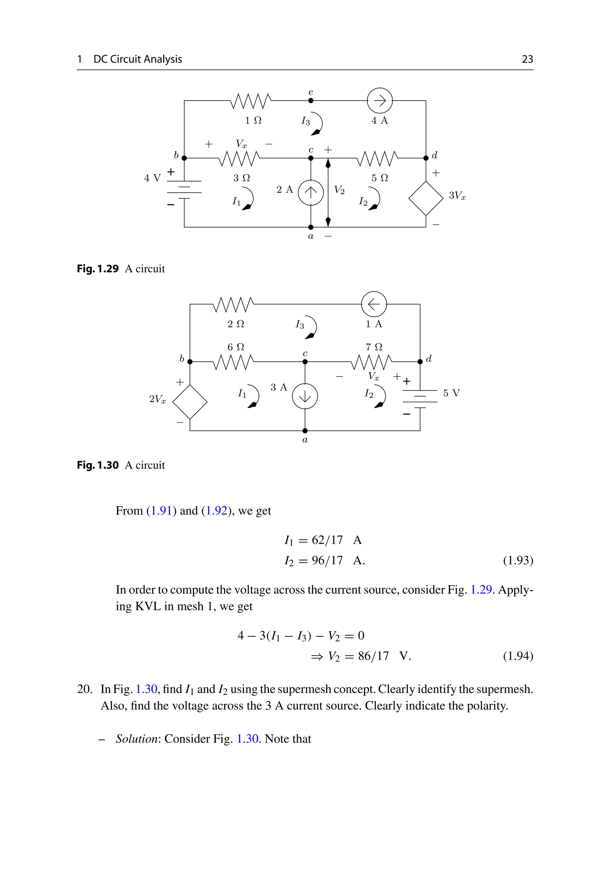
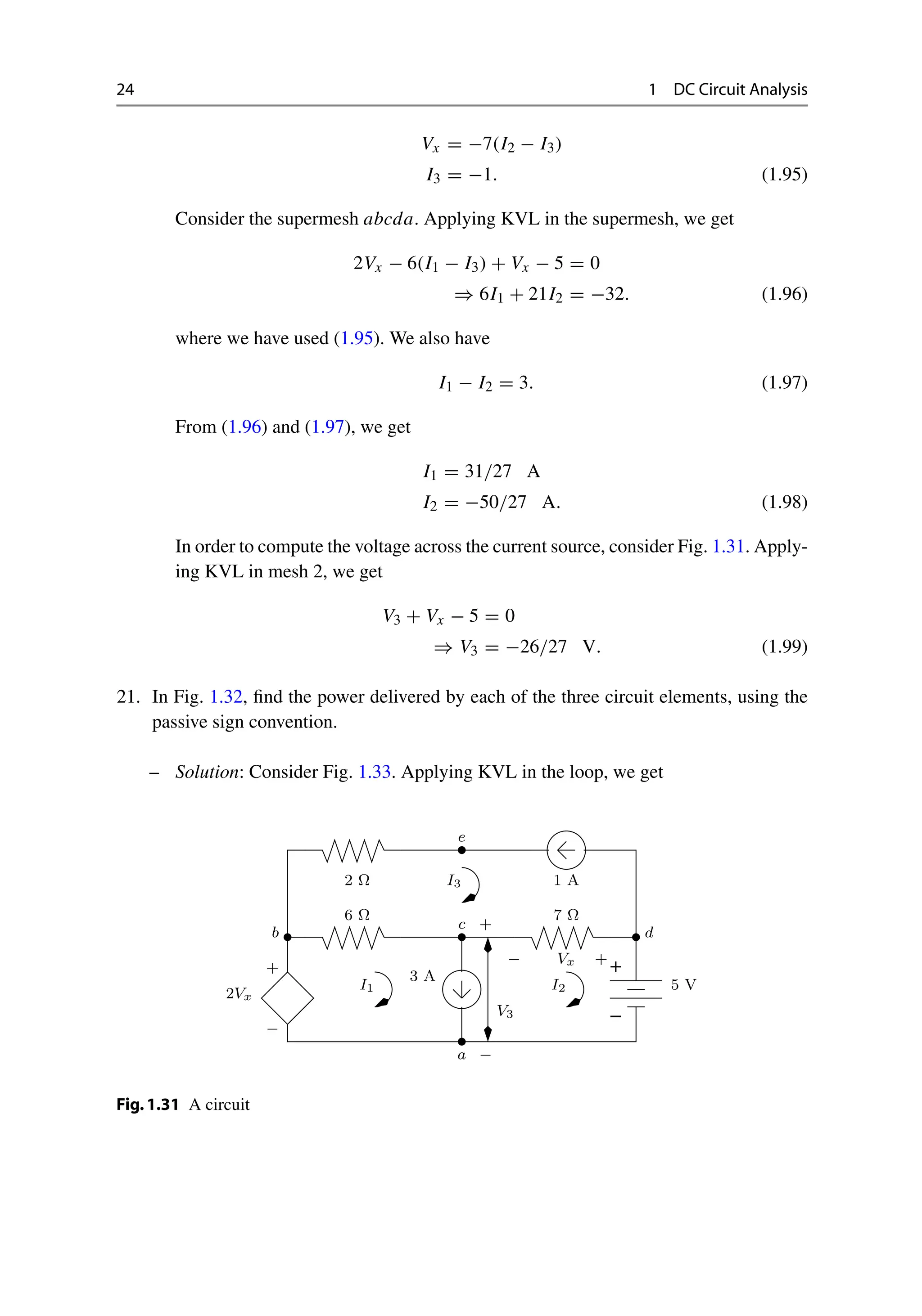
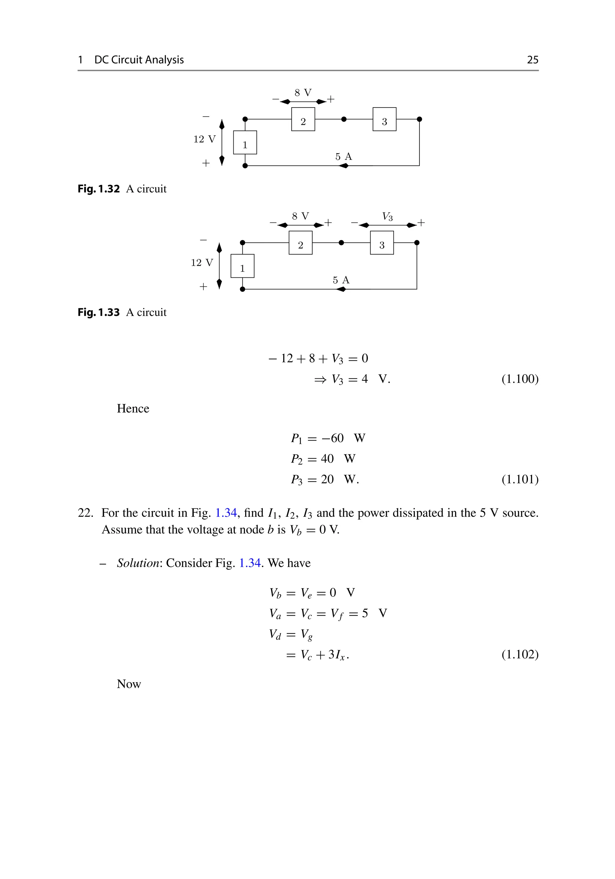
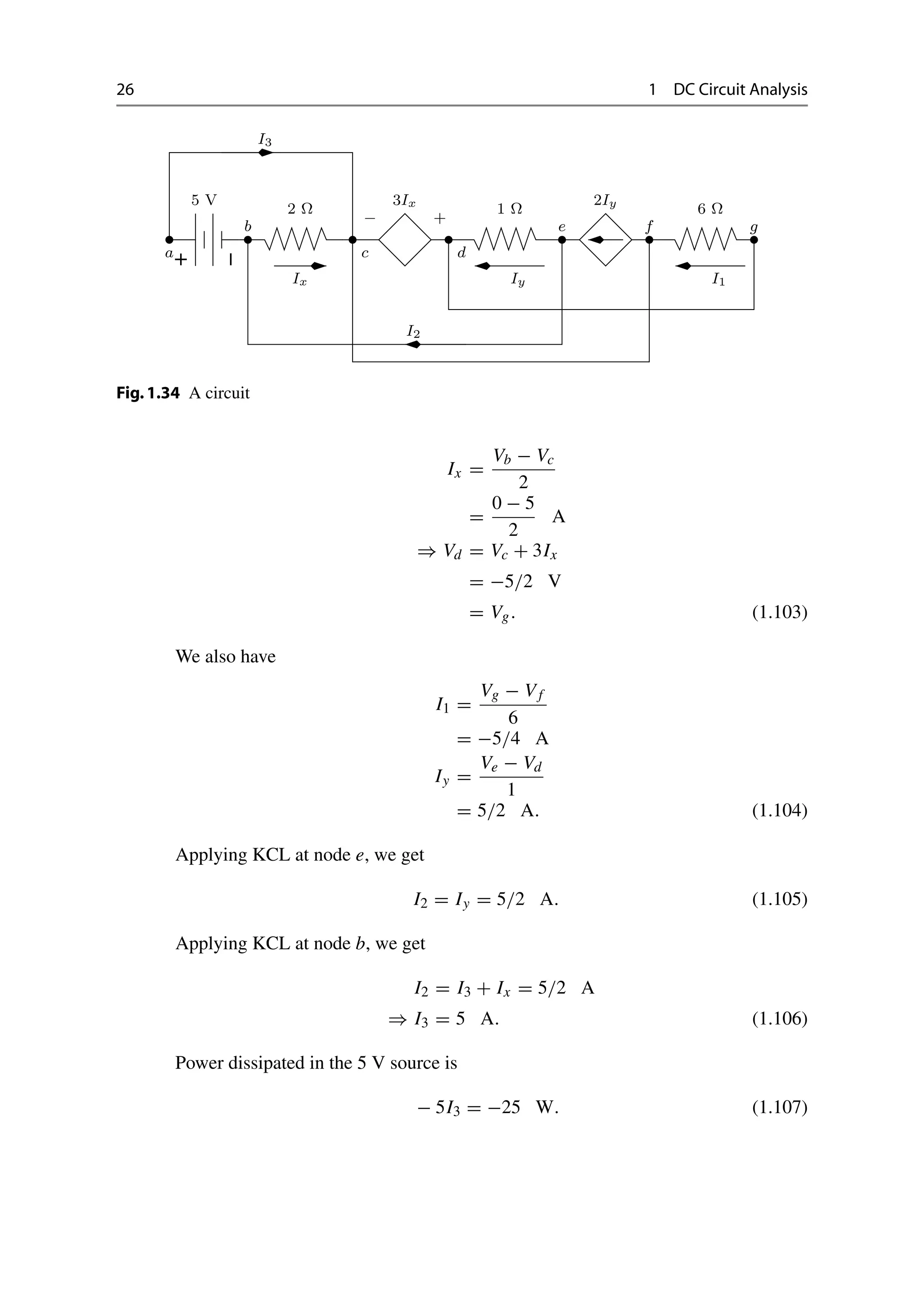

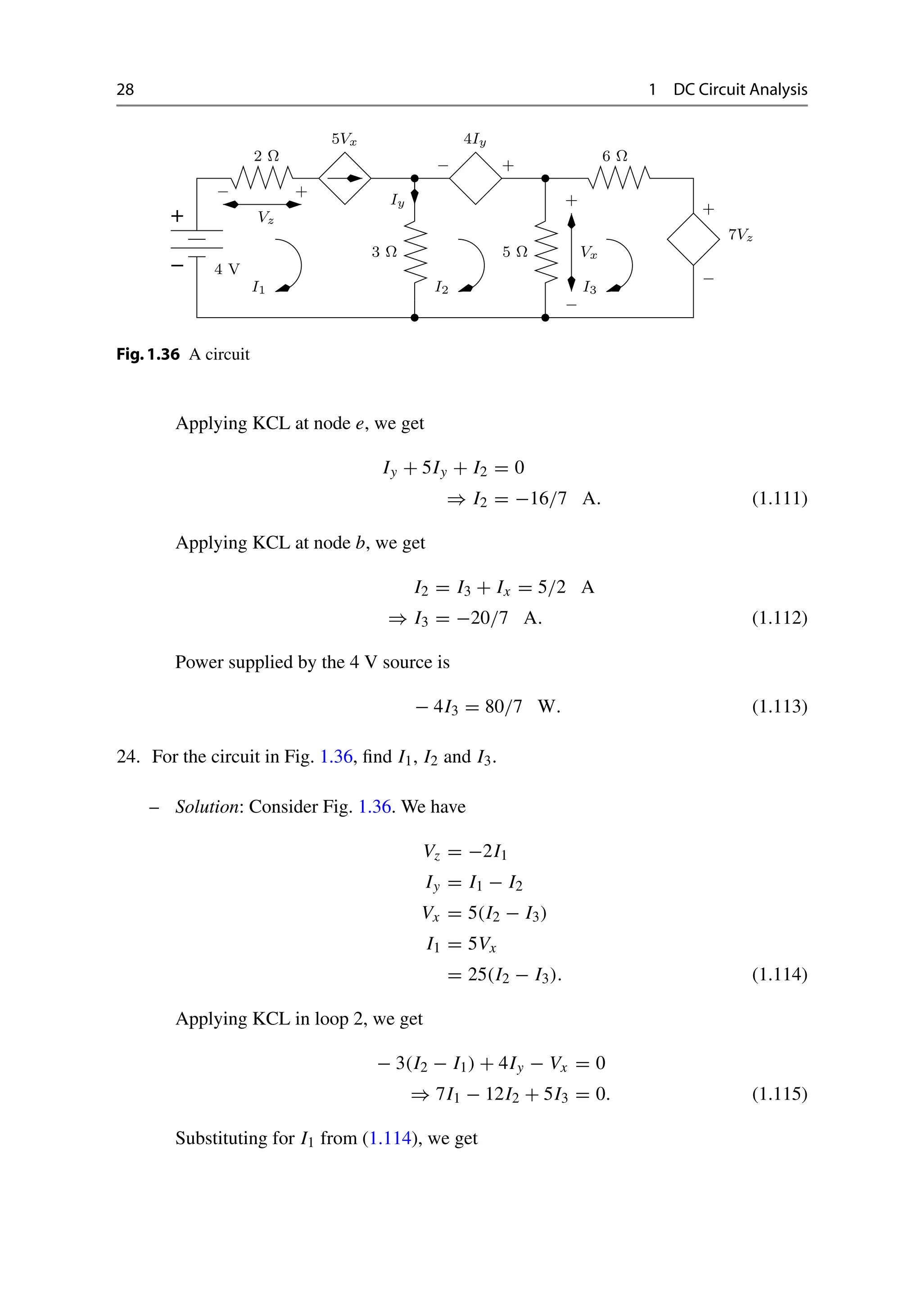

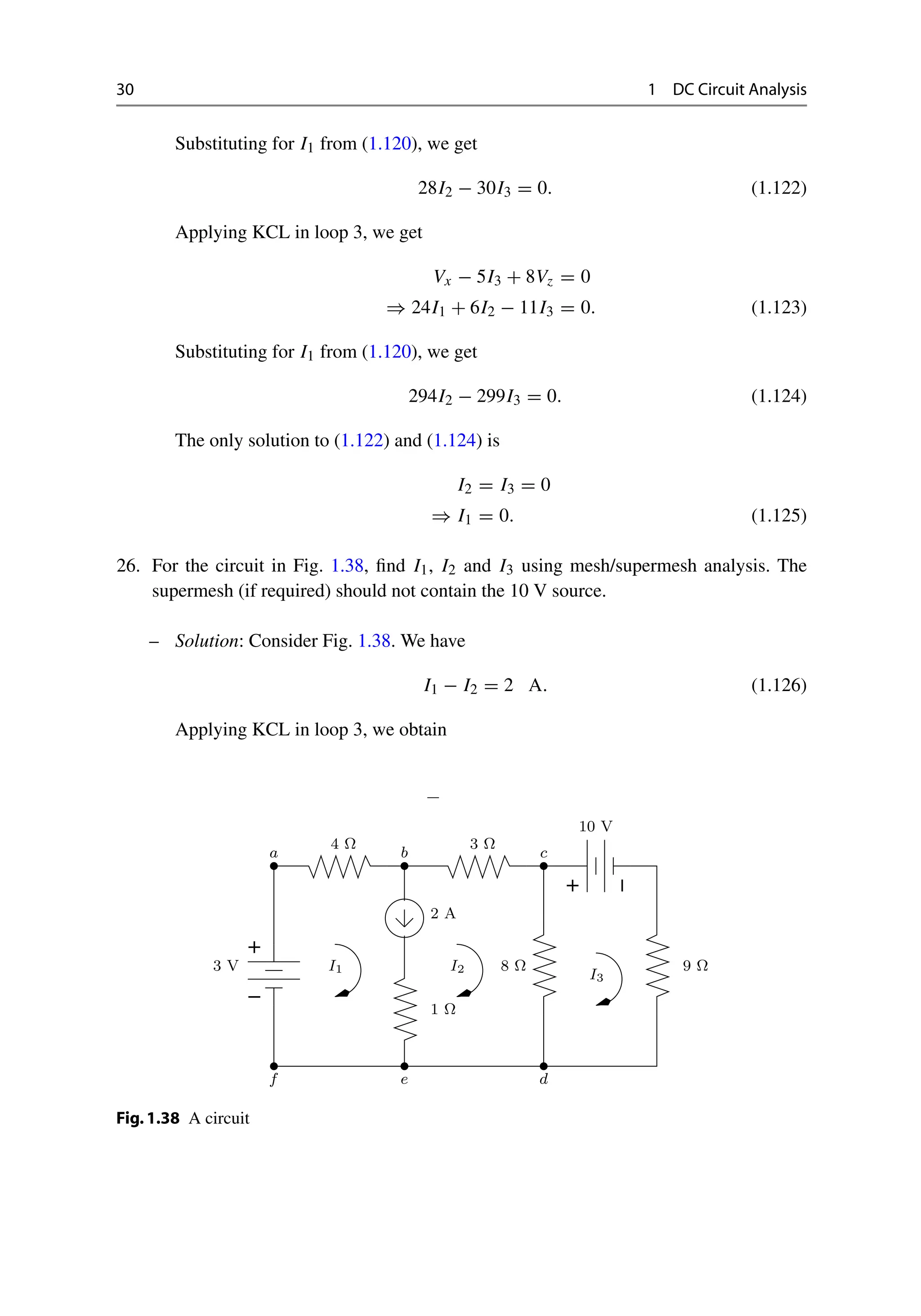
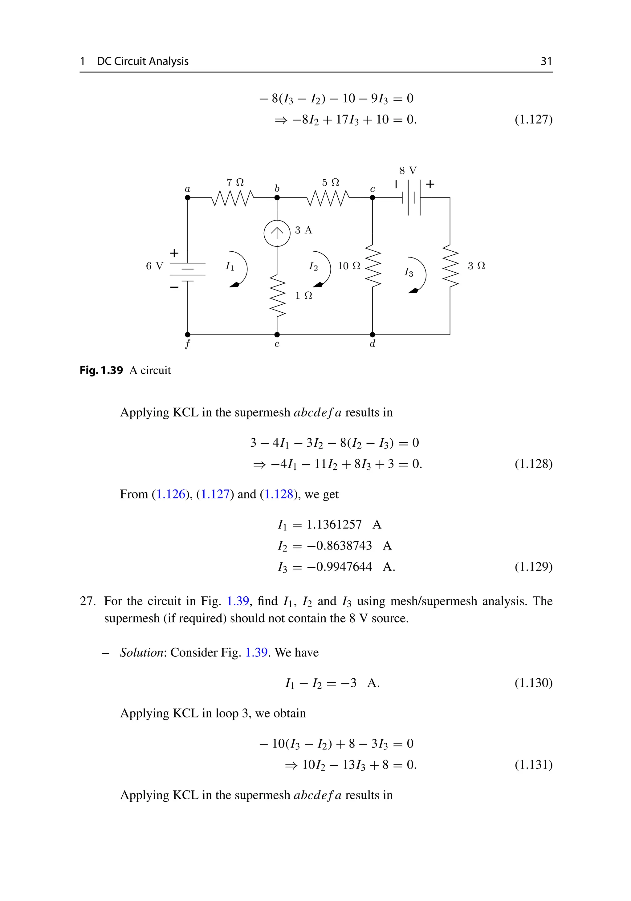
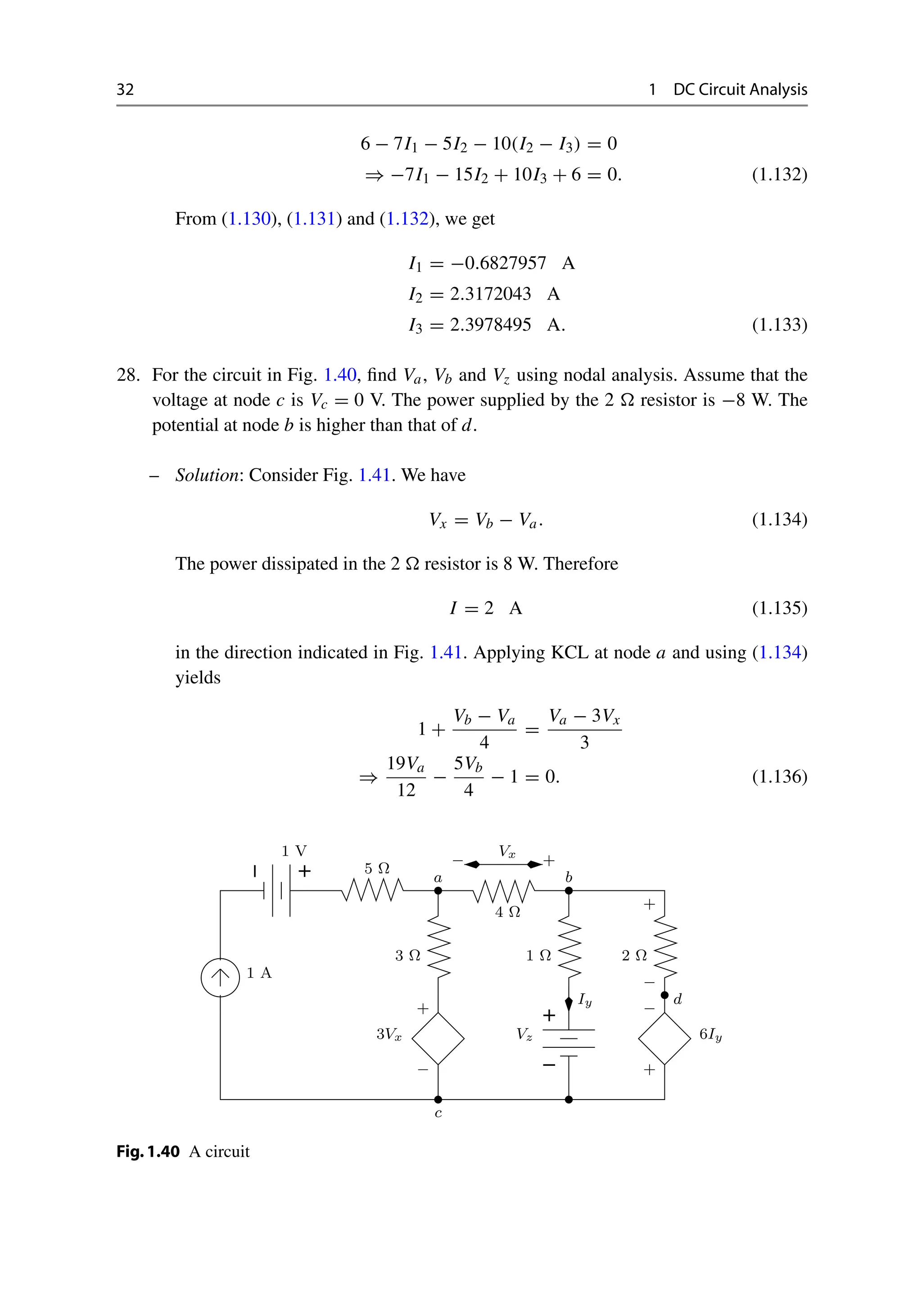
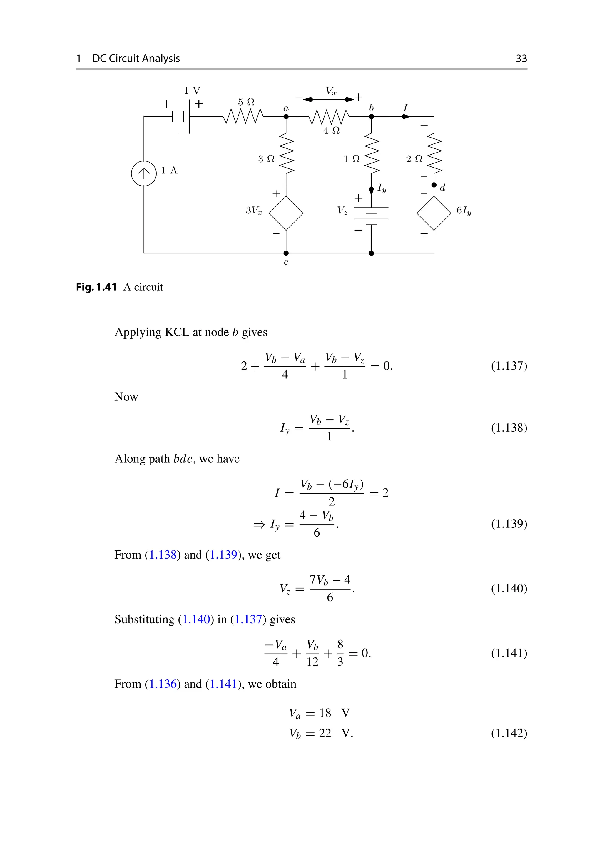
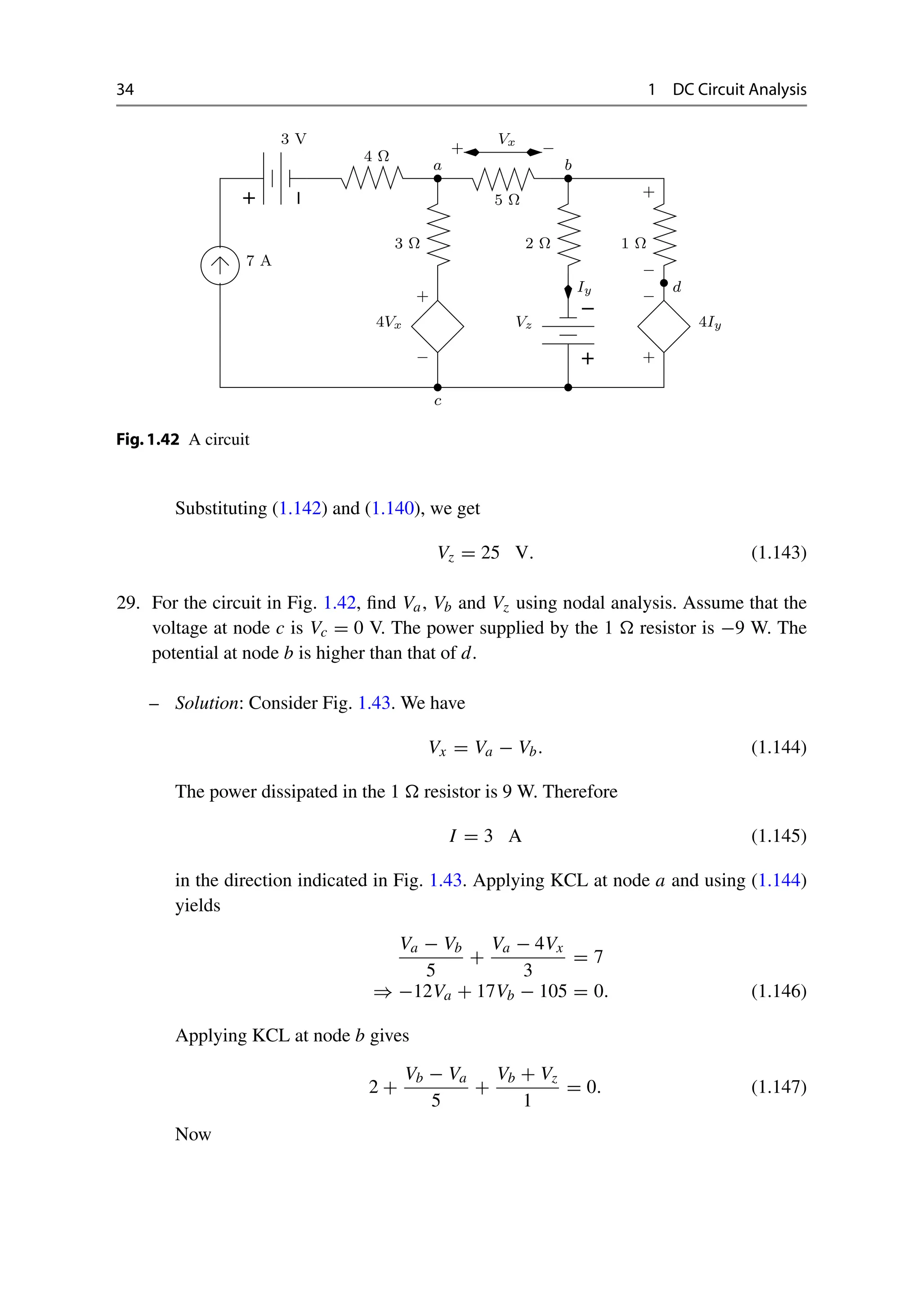
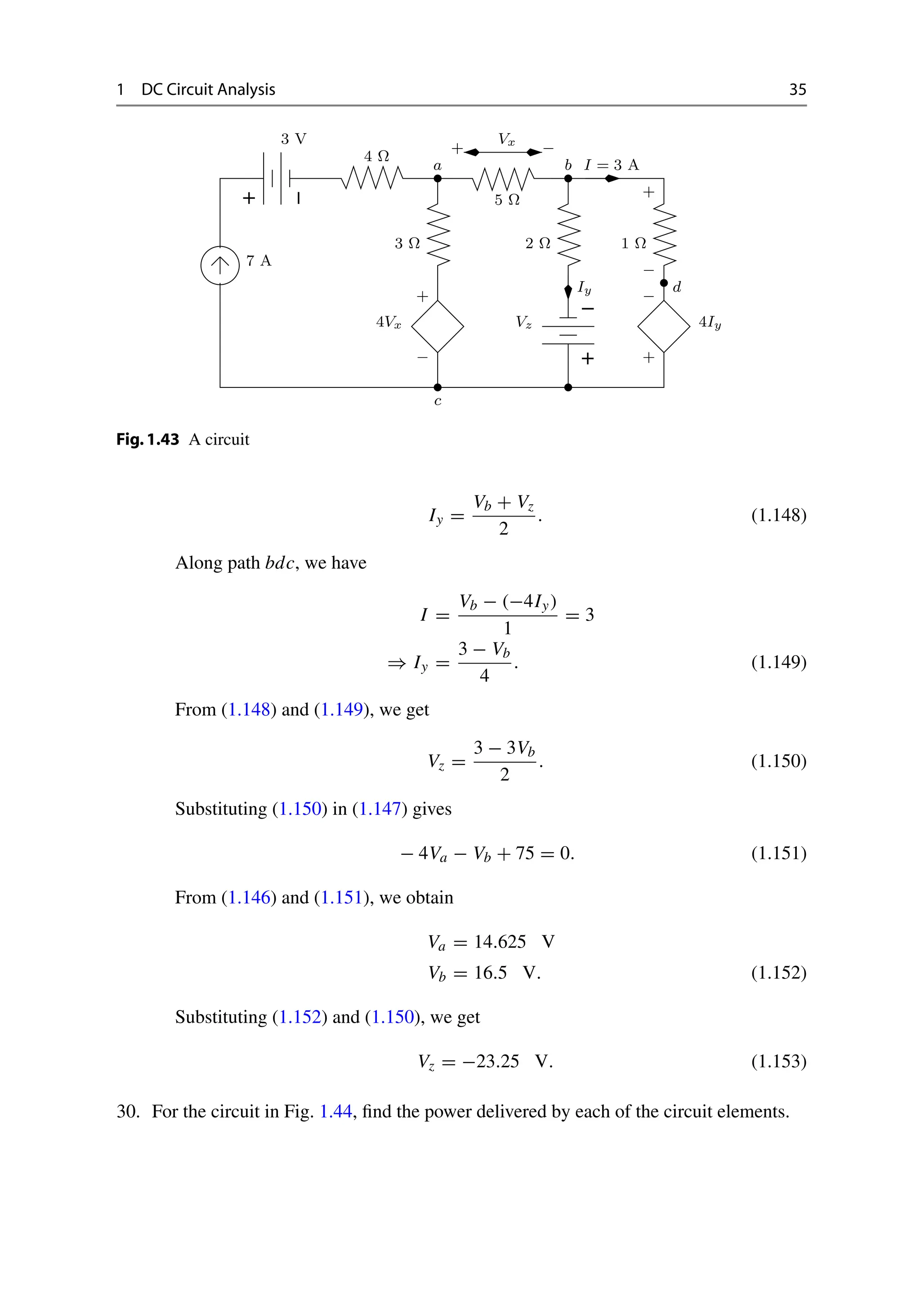
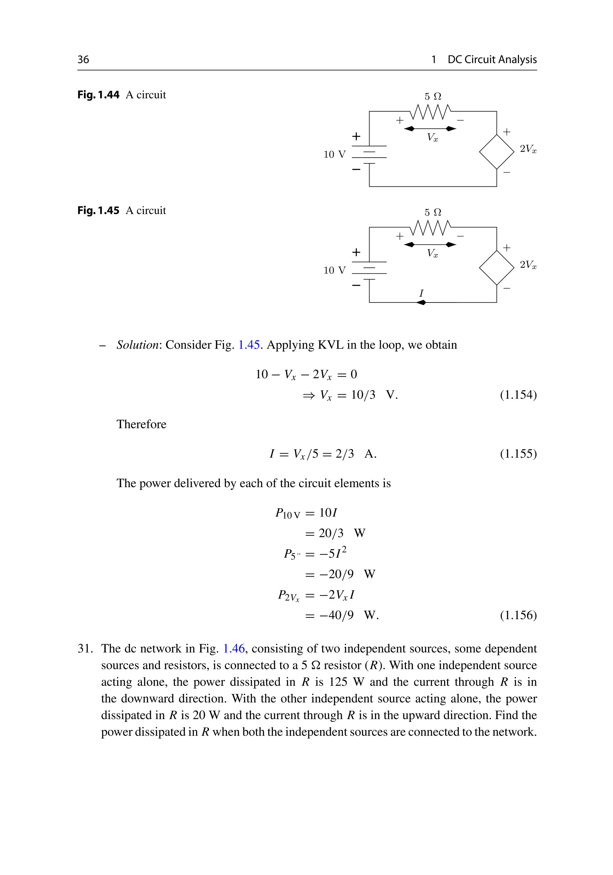
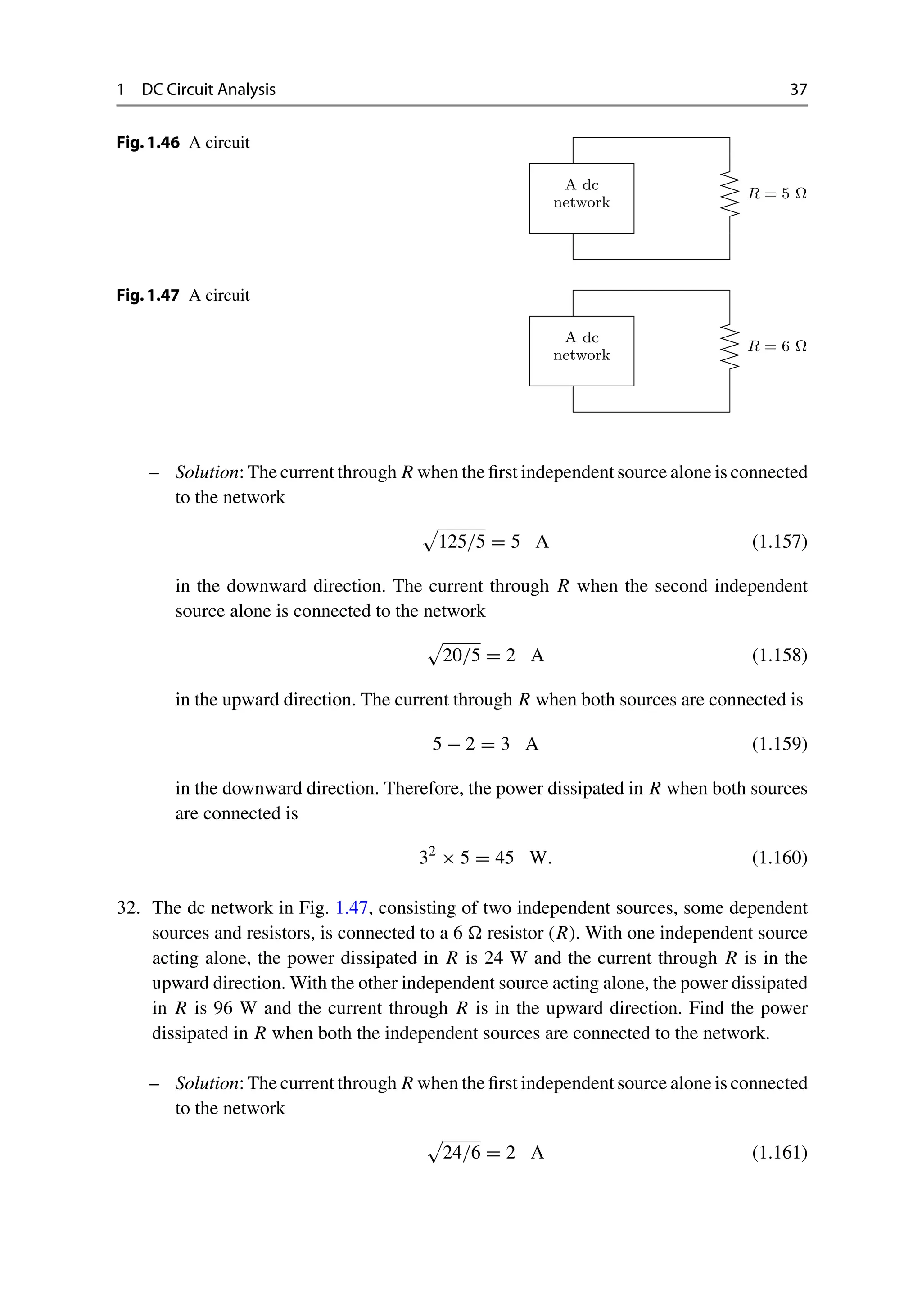


![This ebook is for the use of anyone anywhere in the United States
and most other parts of the world at no cost and with almost no
restrictions whatsoever. You may copy it, give it away or re-use it
under the terms of the Project Gutenberg License included with this
ebook or online at www.gutenberg.org. If you are not located in the
United States, you will have to check the laws of the country where
you are located before using this eBook.
Title: How to Do Chemical Tricks
Author: active 1894-1902 A. Anderson
Release date: September 30, 2015 [eBook #50100]
Most recently updated: October 22, 2024
Language: English
Credits: Produced by Craig Kirkwood, Demian Katz and the Online
Distributed Proofreading Team at http://www.pgdp.net
(Images
courtesy of the Digital Library@Villanova University
(http://digital.library.villanova.edu/).)
*** START OF THE PROJECT GUTENBERG EBOOK HOW TO DO
CHEMICAL TRICKS ***](https://image.slidesharecdn.com/23076224-250509193939-8c6bd658/75/Basic-Electronic-Circuits-Problems-And-Solutions-K-Vasudevan-60-2048.jpg)