Download to read offline
![Faults Analysis in Simulated Two Machine Power System
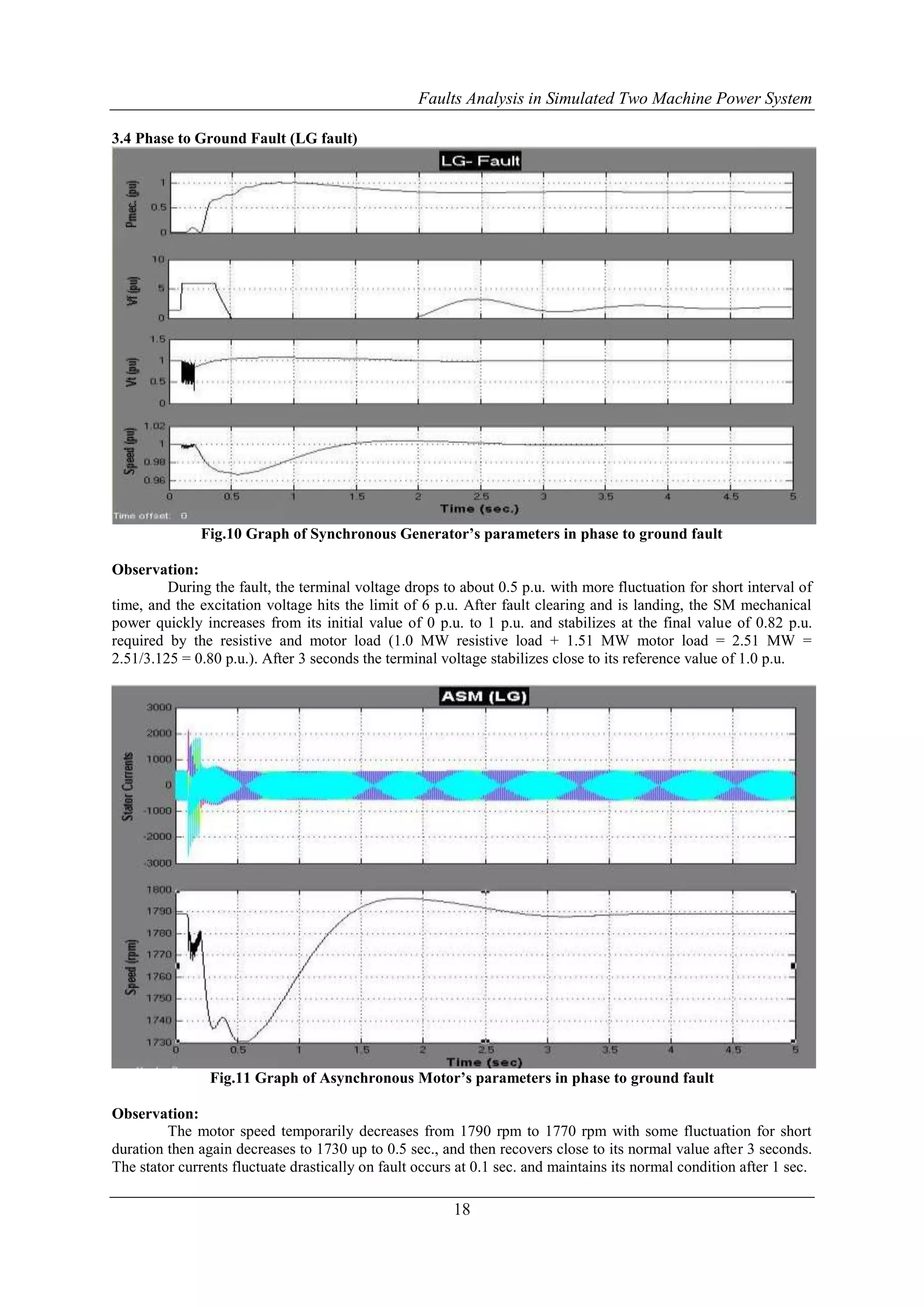
VI. CONCLUSION
In case of synchronous generator, on occurring the fault, the terminal voltage drops to some extent of
duration with more fluctuation in case of thee phase fault as comparison of all unsymmetrical fault and stabilizes
close to its reference value of 1.0 p.u. Whereas the excitation voltage hits the some certain value, which is same
for all the faults. After the fault clearing and is landing, the mechanical power quickly increases from its value
of 0 p.u. to 1 p.u. and stabilizes at the final value of 0.82 p.u. required by the resistive and motor load.
In case of asynchronous motor, the motor speed temporarily decreases from 1790 rpm to more down in
case of three phase fault as comparison of all the fault, but in phase to ground fault the little bit fluctuation is
occurred towards down for short duration , and then recovers close to its normal value after 3 seconds. The
stator currents fluctuate drastically on fault occurs at 0.1 sec. and maintains its normal condition after 1 sec.
REFERENCES
[1]. Badri Ram and D. N. Vishwakarma, Power System Protection and Switchgear, McGraw Hill
19
Education (India) Pvt. Ltd. sixth edition.
[2]. www.mathswork.com
[3]. www.powersolution.com
[4]. MATLAB / SIMPOWER SYSTEM help contained.
[5]. Stanley H. Horowite, Power System Relaying, RSP Publication, third edition.](https://image.slidesharecdn.com/b1081019-141101054212-conversion-gate01/75/International-Journal-of-Engineering-Research-and-Development-10-2048.jpg)

The document presents a detailed analysis of faults in a simulated two-machine power system using MATLAB, focusing on the stability and response to various types of faults including three-phase, phase-to-ground, and others. It highlights the importance of protective devices and relays in maintaining system integrity during faults, describing the impact of these faults on electrical and mechanical parameters. The findings emphasize the critical clearing times and recovery of system stability after disturbances, outlining the necessity for efficient fault detection and isolation to prevent equipment damage.


![See4423 chapter1 introduction[1]](https://cdn.slidesharecdn.com/ss_thumbnails/see4423chapter1introduction1-110307213255-phpapp01-thumbnail.jpg?width=640&height=640&fit=bounds)


