Download to read offline
![1
Data Bulletin
0100DB0402R3/06
3/2006
Cedar Rapids, Iowa, USA
Arc-flash Application Guide
Arc-flash Energy Calculations for Circuit Breakers and Fuses
Class 100
Retain for future use.
INTRODUCTION The idea that short-circuits or faults in an electric power system are
undesirable is certainly not a novel concept. Recently, however, arcing
faults have begun to receive an increasing amount of attention as a
particularly damaging and potentially dangerous type of fault. Arcing fault
current is fault current that flows through the air, unlike “bolted” fault
current, which flows through conductors, busbars, or other equipment that
is (ideally) designed to withstand its effects. This current flow, through air,
releases a great deal of energy in the form of heat and pressure. In
controlled applications, such as arc welding, electrical arcs can be useful.
However, an “arc-flash,” which refers to the uncontrolled release of such
energy during an arcing fault, can result in significant damage to
equipment or worse, injury or death to workers exposed to the fault.
Estimates indicate that 10–15 serious arc-flash
incidents—those that result in burn injuries
requiring treatment in a burn center—occur each
day in the U.S., so it is not surprising that
awareness of the hazards associated with arc-
flash continues to grow. Present Occupational
Safety and Health Administration (OSHA)
regulations do not specifically address arc-flash
hazards, but industry standards such as National
Fire Protection Association (NFPA) 70E-2004,
Standard for Electrical Safety in the Workplace,
provide information on safe work practices and
required protective equipment for electrical
workers exposed to arc-flash hazards. OSHA
has begun to write citations based on the
NFPA 70E requirements. The National Electric
Code (NEC) 110.16 also requires that many
types of electrical equipment be field marked to
warn of potential arc-flash hazards [1].
The Personal Protective Equipment section of
this guide presents background information on
personal protective equipment (PPE) that can
help protect workers from arc-flash hazards.
The Calculation Methods section discusses three primary calculation
methods that are used to assess hazard levels and for the selection of
proper PPE. In general, the three methods do not produce identical results,
but the section Which Calculation Method is Correct? discusses several
arc-flash analysis principles that will help insure that the correct method is
chosen and that accurate results are obtained. Comparisons of the arc-
flash protection provided by several common overcurrent protective
devices are presented in the Device Comparisons section, while the
Conclusions section presents a summary of the items discussed in this
guide.
0100-0000](https://image.slidesharecdn.com/arc-flash-application-guide-200526171239/75/Arc-flash-application-guide-1-2048.jpg)
![Arc-flash Application Guide 0100DB0402R3/06
Personal Protective Equipment 3/2006
© 2004–2006 Schneider Electric All Rights Reserved2
PERSONAL PROTECTIVE
EQUIPMENT
While properly maintained equipment and safe work practices can help to
minimize the probability that an arcing fault might be initiated, workers
potentially exposed to this hazard must still be adequately protected. The
severity of the hazard related to an arcing fault is measured by the amount
of energy that an arc delivers to an exposed worker. Calculation of this
“incident energy,” which is commonly measured in calories per square
centimeter (cal/cm2
) or joules per square centimeter (J/cm2
), provides a
basis for selection of proper PPE, including flame-resistant clothing, flash
suits, arc hoods, and the like. Also important to note is the flash-protection
boundary, the distance from a fault source inside which the incident energy
level exceeds 1.2 cal/cm2
, a level that can cause second degree burns on
exposed skin.
Both the incident energy and the flash-protection boundary vary based on
many parameters. Among the most important factors are the system
voltage, the arcing fault current level, the distance from a worker to the fault
source, and the duration of the fault. As such, the hazard level depends on
many system variables, including equipment type, prospective bolted fault
currents, and characteristics of the upstream protective devices. An analysis
of the potential arc-flash hazard at a given system location should be
performed so that workers can select and use appropriate levels of PPE.
Too little PPE leaves workers inadequately protected, and is therefore
obviously undesirable. Too much PPE is also undesirable, as it may hinder
movement and increase the level of risk associated with a specific work
task, or may create other hazards such as increased heat stress. Three
common methods that may be used to perform arc-flash analyses are
discussed further in the Calculation Methods section.
NFPA 70E-2004 defines five categories of protective clothing based on the
degree of protection provided by each class, which are defined in the PPE
“matrix” of Table 130.7(C)(10). PPE is assigned an Arc Rating (cal/cm2),
which defines the “...maximum incident energy resistance demonstrated by
a material.” The protective clothing characteristics are summarized in
Table 1.
Non-fire Resistant (FR) cotton has no arc rating, and can only be used at
locations and/or working distances having low available incident energy.
Within the flash-protection boundary, adequate protective clothing is
required. As the energy level increases, more layers of FR clothing are
needed to afford adequate protection. Non-FR synthetic clothing, including
synthetic-cotton blends, is not allowed at all, as it can easily ignite and/or
melt into the skin and aggravate a burn injury.
Note that PPE is to be considered a last line of defense rather than a
replacement for safe work practices or engineering controls that can reduce
the exposure to arc-flash hazards. Equipment should be placed in an
electrically safe work condition whenever possible. See NFPA 70E-2004 for
additional details on safe work practices.
CALCULATION METHODS As understanding of the arc-flash hazard has grown, several methods for
calculating the arc-flash hazard have been developed. Three of these
methods will be examined in this section—the theoretical model, the
equations and tables used in NFPA 70E-2004, and the calculation methods
presented in IEEE Std 1584™- 2002.
THEORETICAL MODEL Ralph H. Lee developed a theoretical model for calculation of arc-flash
energy in a paper published in 1982 [2]. Prior to this, arcing faults had been
recognized as damaging to electrical equipment and as a potential safety
hazard, but Lee’s work was one of the first—if not the first—to quantitatively
Table 1: Protective Clothing
Characteristic
(from NFPA 70E-2004)
Clothing
Category
Clothing
Description
Number
of Layers
Minimum
Arc Rating
of PPE
(cal/cm2
)
0
Untreated Natural
Fiber Clothing
1 N/A
1
Fire Resistant
Shirt and Fire
Resistant Pants
1 4
2
Cotton Underwear
plus Category 1
2 8
3
Fire Resistant
Coverall
Over Category 2
3 25
4
Multi-layer
Flash Suit
Over Category 2
4 40](https://image.slidesharecdn.com/arc-flash-application-guide-200526171239/75/Arc-flash-application-guide-2-2048.jpg)
![0100DB0402R3/06 Arc-flash Application Guide
3/2006 Calculation Methods
© 2004–2006 Schneider Electric All Rights Reserved 3
assess the relationships between the energy produced by arcing faults, the
working distance, and the potential hazard to exposed workers. Lee
recognized that arcing faults are sources of intense heat and used heat
transfer equations to determine the effect of this heat energy on human
skin. Equations were presented that allowed for calculation of “just curable”
and “fatal” burn distances based on the value of bolted fault current and the
fault clearing time.
At the time, no testing had been performed to investigate the relationship
between bolted fault current and arcing fault current, so Lee concluded that
the arcing energy calculations should be based on the worst-case condition,
i.e., when the voltage across the arc is equal to half the system voltage.
Later testing showed that actual incident energy levels reached a maximum
of 79% of the theoretical value in a 600 V system and only 42% in a 2400 V
system [3], as the voltage across the arc was actually less than that
required to produce maximum arc power. The results of the theoretical
model tend to be conservative for any system, but are even more
conservative for systems operating at 1 kV or higher.
A more accurate calculation of arcing fault current is required to achieve
more accurate results. In addition, since the theoretical model does not take
into account other important factors, such as whether the arcing fault occurs
in open air or inside an equipment enclosure, it is not suitable for calculation
of incident energy levels or flash-hazard boundaries in a typical industrial or
commercial facility. The model is still useful, however, for calculating energy
levels in situations where no other method has been developed. Equations
based on Lee’s work are included in IEEE 1584 to cover system types that
are not otherwise covered by the IEEE 1584 equations, such as open-air
transmission or distribution systems, open-air substations, or systems
operating above 15 kV.
NFPA 70E-2004 Section 130.3(A) of NFPA 70E-2004 contains equations that allow for
calculation of flash-protection boundary distances for systems operating at
600 V or less. For systems operating above 600 V, the flash-protection
boundary is defined as “...the distance at which the incident energy level
equals 1.2 cal/cm2
” (or 1.5 cal/cm2
if the fault clearing time is less than 0.1
second). No equations are presented that allow for the determination of
distances for systems over 600 V. Annex D of NFPA 70E-2004 contains
equations for the calculation of incident energy levels and flash-protection
boundaries based on the theoretical model, on testing performed on 600 V
systems [4], and from IEEE 1584. No recommendations are given as to the
preferred calculation method.
NFPA 70E-2004 also provides a method for selecting PPE that requires little
or no calculation. Table 130.7(C)(9)(a) assigns “Hazard/Risk Category”
values for typical work tasks that might be performed on common types of
equipment, such as the insertion of starter buckets in a 600 V class motor
control center. The Hazard/Risk Category values correspond to the five
categories of PPE so that a worker may determine the level of clothing that
is required by simply finding the appropriate work task in the table. Included
with the table are several footnotes that define fault current ranges and fault
clearing times for which the Hazard/Risk category values are valid. For
system conditions that fall outside these parameters—such as with a main
lug switchboard protected by a slow-acting utility transformer primary fuse,
which may not clear a fault in the one second time frame that is assumed—
the tables may not be used to select PPE. Even for some conditions that do
fit the system conditions defined by the table, the recommended PPE may,
in some cases, be inadequate. For example, for a section of 480 V-class
switchgear, the assumed system parameters are “up to 65 kA available, and
up to 1.0 second clearing time.” Based on 65 kA bolted fault current and 1.0](https://image.slidesharecdn.com/arc-flash-application-guide-200526171239/75/Arc-flash-application-guide-3-2048.jpg)
![Arc-flash Application Guide 0100DB0402R3/06
Which Calculation Method is Correct? 3/2006
© 2004–2006 Schneider Electric All Rights Reserved4
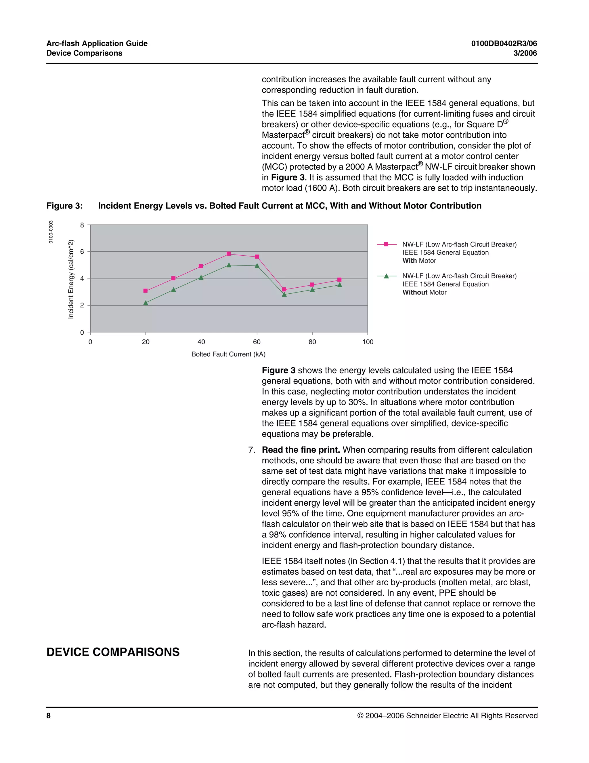
second fault duration, IEEE 1584 calculates an incident energy of
69 cal/cm2
at a 24” working distance, but Table 130.7(C)(9)(a) does not call
for PPE above Category 3 for any listed work task. Despite some
deficiencies, the table is still useful, particularly in facilities where little or no
system information is available.
IEEE STD 1584 IEEE Std 1584™-2002, IEEE Guide for Performing Arc-flash Hazard
Calculations, presents the most comprehensive set of equations to date for
calculating incident energy levels and flash-protection boundaries. Empirical
equations are given that cover systems at voltage levels ranging from 208 V
to 15 kV and for available bolted fault currents ranging from 700 A to
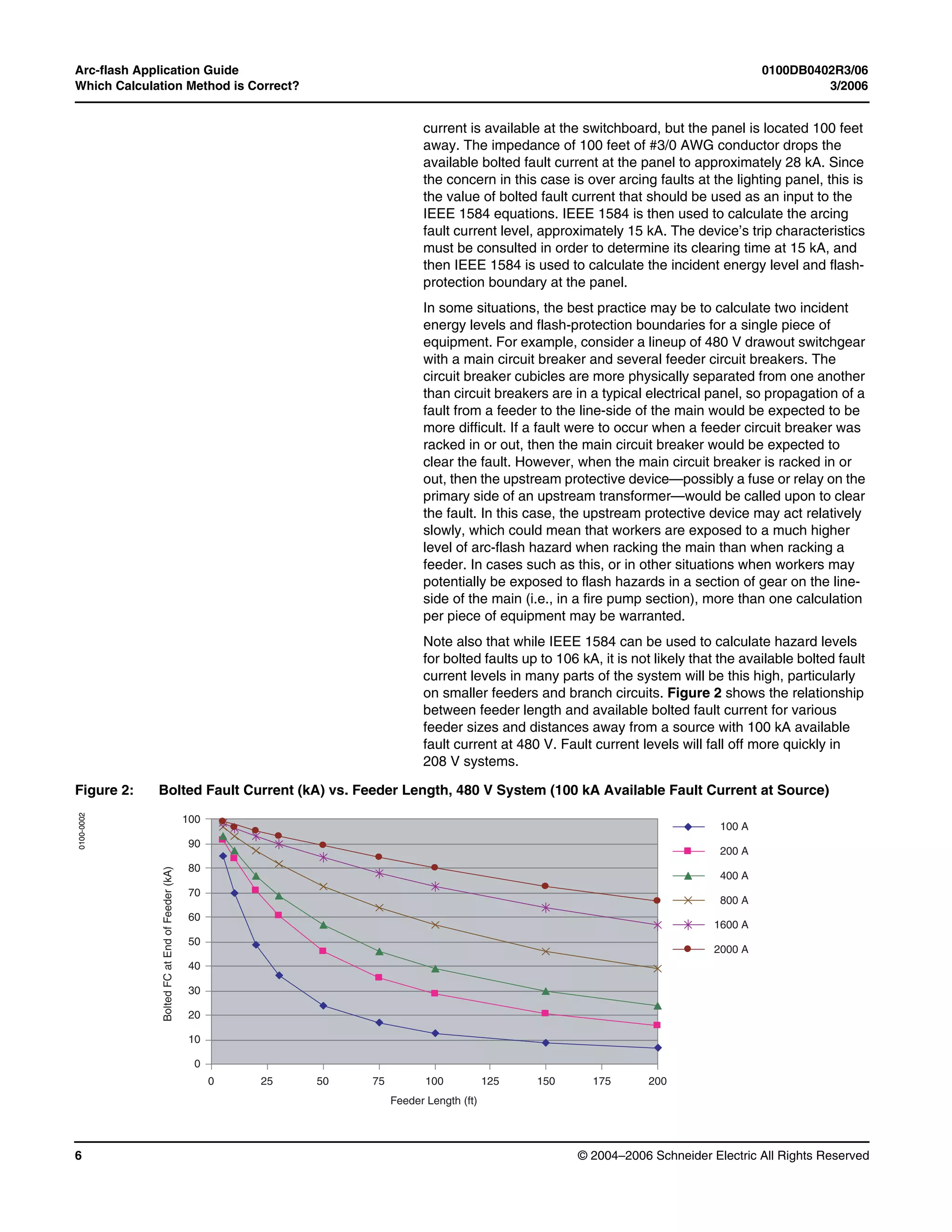
106 kA, sufficient to cover the majority of low-voltage and medium-voltage
installations. The equations are rather complex if calculations are to be
performed by hand, though the equations are easily implemented in a
spreadsheet or in other computer software. Simplified equations are also
provided for several common protective device types, including current-
limiting Class RK1 and Class L fuses (up to 2000 A), as well as for various
types of circuit breakers (100–6300 A). The fuse equations are based on
testing of one manufacturer’s current-limiting fuses. The breaker equations
are based on calculated results and are “generic” equations that correspond
to a general class or frame size of breakers rather than to a specific device.
They may be used if specific information about the breaker’s trip
characteristics is not available. In addition, restatements of the theoretical
equations are provided for calculation of energy levels in systems that fall
outside the scope of the test data. Future testing and analysis may result in
revisions of or additions to the present IEEE 1584 methods, but at present,
it represents the state-of-the-art methodology for arc-flash analysis and
should be used when possible. The IEEE 1584 calculation methods have
been implemented in several power system analysis software packages,
including SKM Power*Tools®
and ETAP®
.
WHICH CALCULATION METHOD
IS CORRECT?
In addition to the three methods discussed in Calculation Methods there
are other methods or tools available for calculation of arc-flash hazard levels
including various Windows and DOS-based shortcut calculator programs,
IEEE 1584-based calculators on equipment manufacturer’s web sites, or
equipment-specific equations, such as those developed for the Square D®
Masterpact®
NW and NT “low arc-flash” (LF and L1F) circuit breakers [5].
Even IEEE 1584 presents two alternate calculation methods for many
situations—the general equations and the simplified equations for circuit
breakers and fuses. For a given system location, one can calculate several
different values for incident energy levels or for the flash-hazard boundary
distance. While the calculation results may be close to one another in many
situations, this may not always be the case.
How can one be sure which method produces the best results for a given
situation? No single calculation method is applicable to all situations, but
several principles may be followed to ensure that the best results are
obtained in a given situation:
1. Verify that actual system conditions fall within the method’s range
of applicability. Many of the available calculation methods are at least
partially based on empirical equations—i.e., equations derived from test
results. These equations are valid over the range of system conditions
where testing was performed, but cannot be extended to other situations
with a high degree of confidence. For example, the equations in
IEEE 1584 cannot be used to calculate arc-flash hazard levels at
locations with greater than 106 kA available bolted fault current or in a
DC system. This principle is also important when using the NPFA 70E
tables to assess arc-flash hazard levels, as the tables are based on](https://image.slidesharecdn.com/arc-flash-application-guide-200526171239/75/Arc-flash-application-guide-4-2048.jpg)

![0100DB0402R3/06 Arc-flash Application Guide
3/2006 Which Calculation Method is Correct?
© 2004–2006 Schneider Electric All Rights Reserved 7
5. Quantify the variables. As mentioned previously, the system voltage
level, the level of arcing fault current, and the clearing time of the fault
are among the most significant parameters that determine the level of
arc-flash hazard in a system. However, several other variables must be
considered—at least when using the IEEE 1584 general equations—and
they must be determined before incident energy levels or flash-
protection boundaries may be calculated. These variables include:
— Working Distance: Working distance is defined as the distance
from the electric arc to the worker’s face and body (torso). The
incident energy levels drop off fairly quickly as the distance from the
arcing fault is increased, so choosing the correct working distance is
important if an accurate determination of required PPE is to be
made. Typical working distances for various types of equipment are
given in Table 3 of Section 4.8 of IEEE 1584, and range from 18”
(455 mm) for low-voltage panels and MCCs to 36” (910 mm) for
medium-voltage switchgear. When comparing the results of
calculations performed using the IEEE 1584 general equations to
those performed using simplified, equipment-specific equations, note
that the simplified equations assume a fixed working distance
(typically 18”).
— Bus Gap: The length of the arc depends on the gap between phase
conductors or from phase to ground, which is referred to in
IEEE 1584 as the “bus gap.” Longer arcs have higher impedance
values than shorter arcs, and therefore result in a larger voltage drop
across the arc and a lower value of arcing fault current than shorter
arcs. Typical values for bus gaps for various classes of equipment
are given in Table 2 of IEEE 1584.
— Equipment Configuration: Incident energy from an arc in open air
should, in theory, drop as 1/d2 (d=distance) as one moves away from
the source of the arc. Testing of arcs that started in a typical
equipment enclosure (i.e., an “arc-in-a-box”) showed that energy
levels fell off more slowly (1/d1.5) as a result of energy being
reflected off the back and sides of the enclosure and focused in the
direction of the worker. This results in incident energy levels for “in-
box” configurations that may be 20–40% higher at typical working
distances [3, 4]. For power distribution systems in a typical industrial
or commercial facility, practically every arcing fault should be
considered to be an “in-box” configuration.
— System Grounding: Testing showed that system grounding has a
relatively small (but “statistically significant”) impact on incident
energy levels in some cases. The IEEE 1584 calculations differ
slightly depending on whether a system is solidly grounded or
ungrounded (including high-resistance grounding), so a software
program based on IEEE 1584 will require information regarding
system grounding.
6. Be aware of motor contribution. It is widely recognized that motors
contribute to fault current, but IEEE 1584 addresses motor contribution
to a fault only briefly, and other calculation methods generally do not
address it at all. The level of arcing fault current at a given location
depends on the level of bolted fault current, so when motor loads are
present, the motor contribution adds to the arcing fault current as well.
However, this portion of the arcing fault current does not flow through
the upstream protective device, and therefore does not make devices
with inverse-time characteristics trip any faster than they would if the
motor load were not present. Incident energy levels and flash-protection
boundary distances may therefore be increased, as the motor](https://image.slidesharecdn.com/arc-flash-application-guide-200526171239/75/Arc-flash-application-guide-7-2048.jpg)
![0100DB0402R3/06 Arc-flash Application Guide
3/2006 Device Comparisons
© 2004–2006 Schneider Electric All Rights Reserved 9
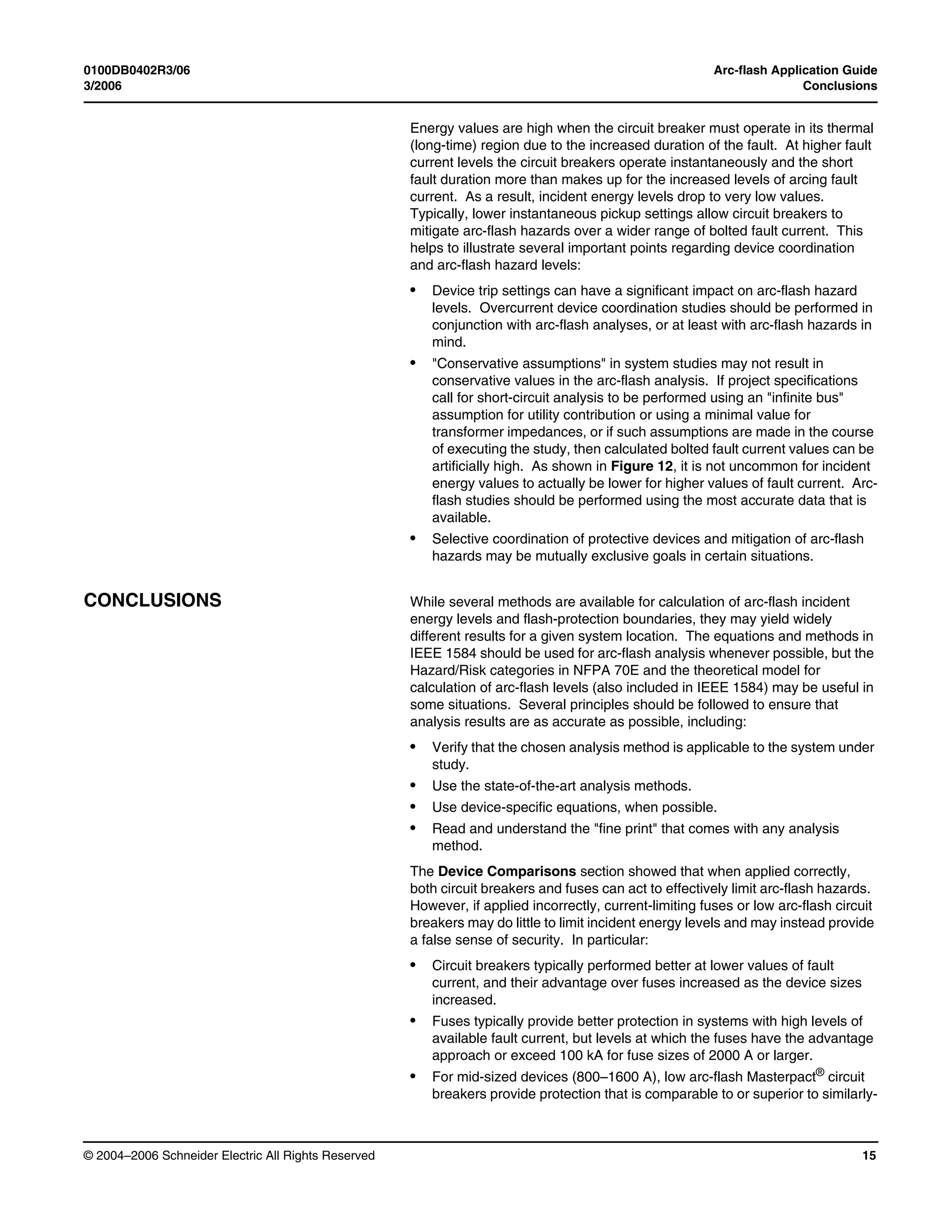
energy calculations—higher incident energy levels correspond to greater
flash-protection boundary distances. Calculations are performed per the
IEEE 1584 general equations or simplified, device-specific equations, as
noted. When the IEEE 1584 general equations are used for calculations
involving circuit breakers, unless otherwise noted, all breakers are set so
that they will trip instantaneously. Calculations were performed assuming a
480 V, solidly grounded system with a working distance of 18 inches and an
“in-box” configuration.
A summary of the relative advantages of the types of devices considered is
given in Table 2. For each type of device, information on conditions if/when
each allows the lowest values of incident energy are provided. The table
also shows if/when the devices allow the use of Category 1 or lower PPE,
the least restrictive (and most comfortable) category of protective clothing.
Current-limiting fuses are Class RK-1 or Class L, depending on the size.
The “Low Arc-flash Circuit Breaker” device type refers to Square D®
Masterpact®
NT-LF and/or NW-LF or NW-L1F circuit breakers, which are
designed to limit the available arc-flash incident energy [5]. The table
assumes that adjustable breakers are set to trip instantaneously. Larger
devices were evaluated for bolted fault currents ranging from
20–100 kA, while smaller devices were evaluated starting at 5 kA bolted
fault current. Note that the table does not consider other application issues
related to breakers and fuses, such as the possibility of single-phasing,
exposure to hazards when fuses are replaced, equipment footprint, and so
forth.
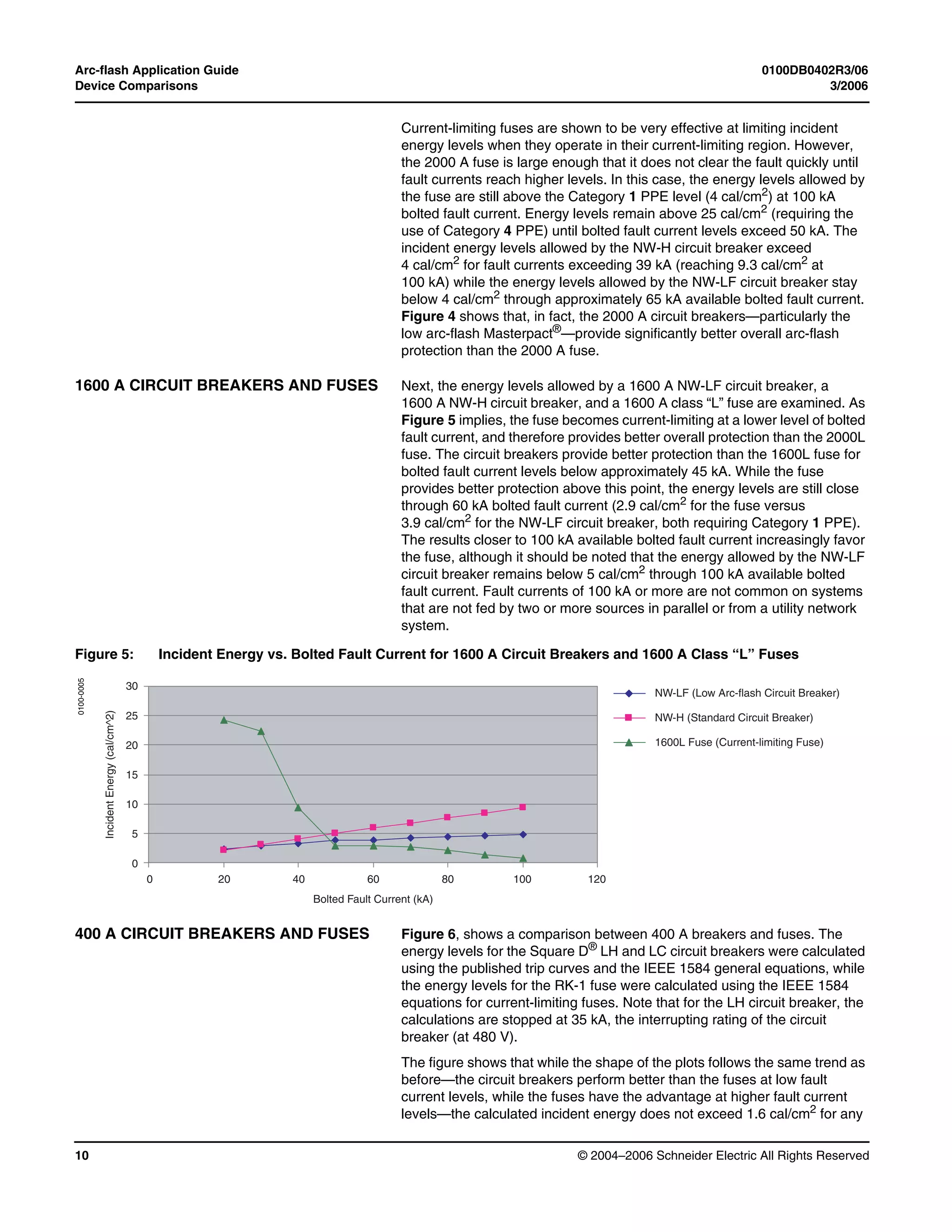
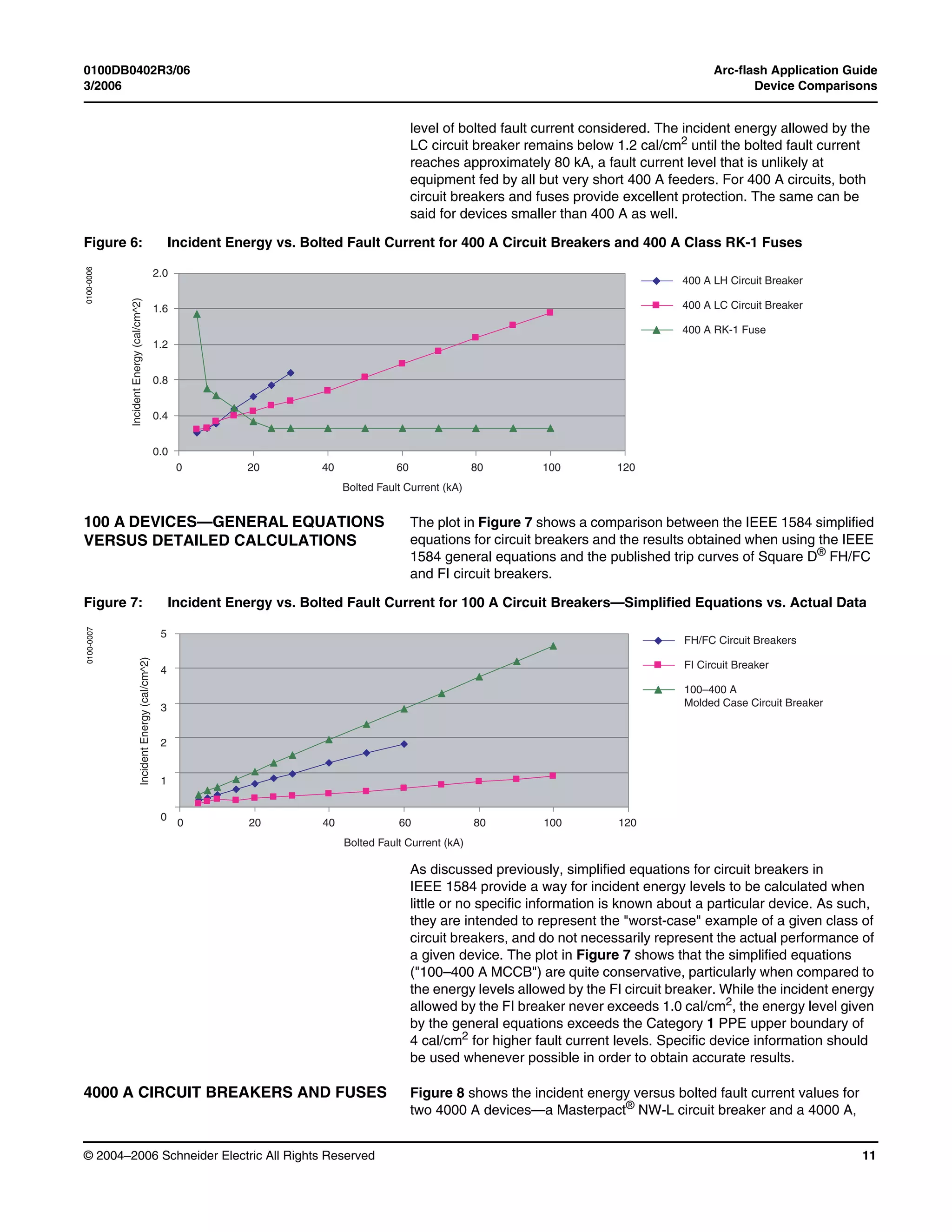
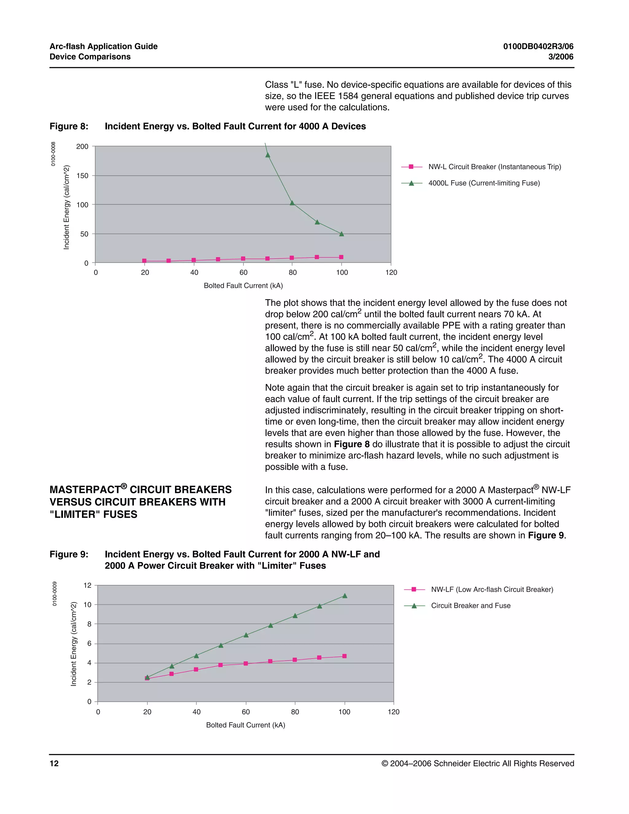
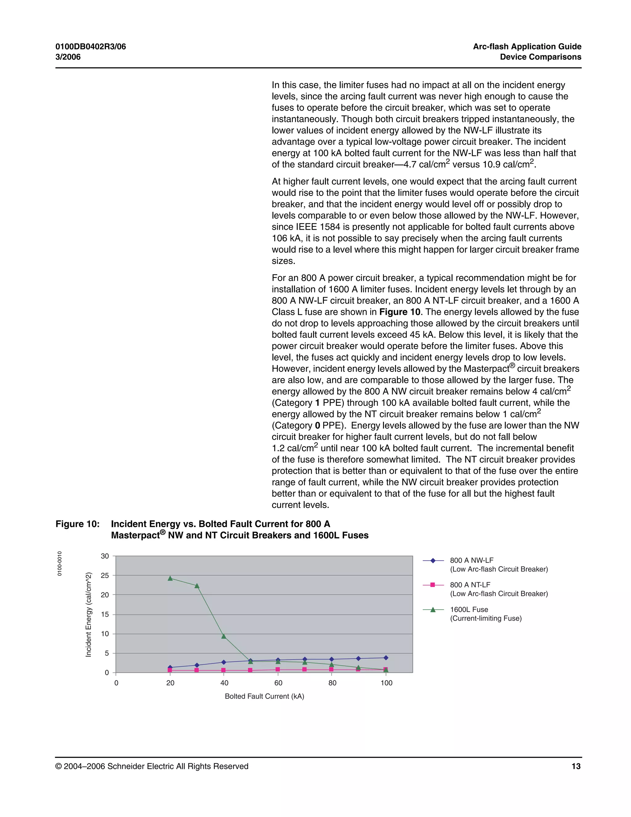
2000 A CIRCUIT BREAKERS AND FUSES Figure 4 shows the incident energy levels allowed by a 2000 A Masterpact®
NW-LF (low arc-flash) circuit breaker, a Masterpact®
NW-H (standard)
circuit breaker, and a 2000 A Class L current-limiting fuse. The energy
levels for the NW-LF circuit breaker are calculated with equipment-specific
equations published by Square D®
, while energy levels for the fuse are
calculated using the IEEE 1584 equations for current-limiting fuses. Energy
levels for the NW-H circuit breaker are calculated using the IEEE 1584
general equations and the published trip curves.
Table 2: Summary of
Device Performance
Device Type Lowest
Incident Energy
Category
0 or 1 PPE?
Fuses ≤400 A
Lower for most
FC values
Yes
Circuit Breakers
≤400 A
Higher but still
below 2 cal/cm2 Yes
Fuses 600–1600 A
When operating in
current-limiting
region
When operating in
current-limiting
region
Circuit Breakers
600–1600 A
Higher than low AF
circuit breaker but
lower than fuse at
low FC
Below 50 kA
bolted FC
Low AF
Circuit Breakers
600–1600 A
At low FC
Below 65 kA
bolted FC
2000 A Fuses No
Above 104 kA
bolted FC
Standard Circuit
Breaker 2000 A
Lower than fuse
below ~95 kA
Below 39 kA
bolted FC
Low AF Circuit
Breaker 2000 A
Yes
Below 65 kA
bolted FC
Fuse > 2000 A No No
Circuit Breaker
> 2000 A
Yes
Below 50 kA
bolted FC
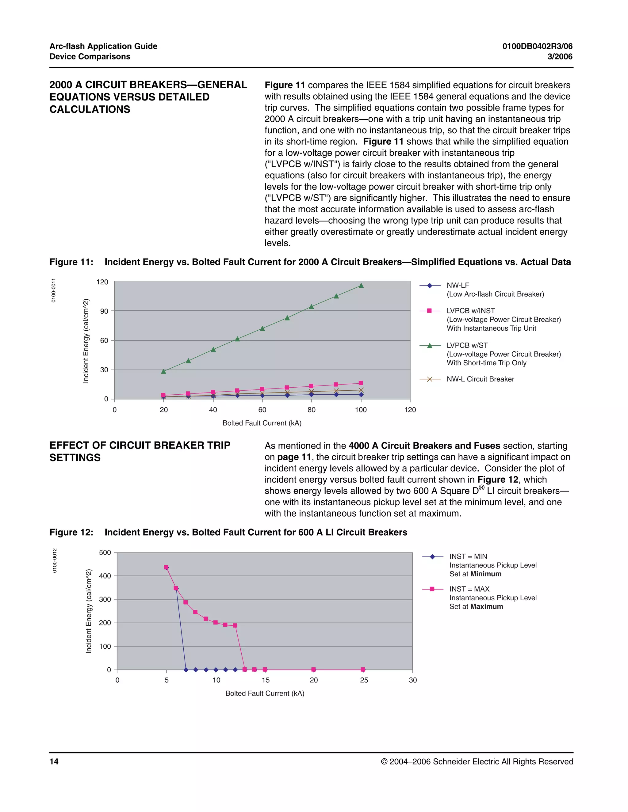
Figure 4: Incident Energy vs. Bolted Fault Current for 2000 A Circuit Breakers and 2000 A Class “L” Fuse
100
75
50
25
0
IncidentEnergy(cal/cm^2)
0 20 40 60 80 100
Bolted Fault Current (kA)
120
NW-LF (Low Arc-flash Circuit Breaker)
NW-H (Standard Circuit Breaker)
2000L Fuse (Current-limiting Fuse)
0100-0004](https://image.slidesharecdn.com/arc-flash-application-guide-200526171239/75/Arc-flash-application-guide-9-2048.jpg)
![Arc-flash Application Guide 0100DB0402R3/06
Data Bulletin 3/2006
Electrical equipment should be installed, operated, serviced, and maintained only by
qualified personnel. No responsibility is assumed by Schneider Electric for any
consequences arising out of the use of this material.
© 2004–2006 Schneider Electric All Rights Reserved
Schneider Electric USA
3700 Sixth Street SW
Cedar Rapids, Iowa 52404
1-888-SquareD (1-888-778-2733)
www.us.SquareD.com
sized fuses. Required PPE does not exceed Category 1 through 65 kA
for the Masterpact®
circuit breakers.
• For smaller devices (400 A or less), both circuit breakers and fuses
generally provide excellent protection.
• Based on recommended sizing of limiter fuses, the fuses have little or no
impact on arc-flash levels for larger frame power circuit breakers. For
smaller frame circuit breakers, they are able to provide protection
comparable to or better than NW-LF and NT-LF circuit breakers only for
systems with high levels of available bolted fault current.
When adjustable circuit breakers are set indiscriminately, increased trip
times can compromise the arc-flash protection that would otherwise be
provided by the circuit breakers. Arc-flash studies should be performed in
conjunction with short-circuit and coordination studies, and in some cases,
selectivity between devices may have to be compromised if arc-flash levels
are to be kept low. As always, PPE should be considered as a last line of
defense, and not as a replacement for safe work practices or engineering
controls that can help limit exposure to arc-flash hazards.
REFERENCES [1] National Fire Protection Association, Inc., NFPA 70, National Electrical
Code, 2002 ed.
[2] R. H. Lee, The Other Electrical Hazard: Electric Arc Blast Burns, IEEE
Transactions on Industry Applications, Vol. IA-18, No. 3 (May/June
1982).
[3] T.E. Neal, A.H. Bingham, and R.L. Doughty, Protective Clothing
Guidelines for Electric Arc Exposure, IEEE Petroleum and Chemical
Industry Conference Record of Conference Papers, Paper No.
PCIC, 96–34 (1996).
[4] R.L. Doughty, T.E. Neal, and H.L. Floyd, Predicting Incident Energy to
Better Manage the Electric Arc Hazard on 600V Power Distribution
Systems, IEEE Petroleum and Chemical Industry Conference
Record of Conference Papers, Paper No. PCIC, 98–36 (1998).
[5] Square D® Data Bulletin 0613DB0202R0603, Arc-flash Protection with
Masterpact® NW and NT Circuit Breakers, (July 2003).](https://image.slidesharecdn.com/arc-flash-application-guide-200526171239/75/Arc-flash-application-guide-16-2048.jpg)

This document discusses methods for calculating arc flash hazards to help select proper personal protective equipment (PPE). It describes three primary calculation methods: 1) Ralph Lee's theoretical model from 1982, 2) equations and tables in NFPA 70E-2004, and 3) the comprehensive equations presented in IEEE Std 1584-2002. The document provides guidelines for determining which calculation method is correct for a given situation, such as verifying the method applies to the system voltages and fault currents and using device-specific equations over general equations. It also summarizes types of PPE defined in NFPA 70E-2004 based on the degree of arc flash protection required.