SlideShare a Scribd company logo
1 of 20
Download to read offline
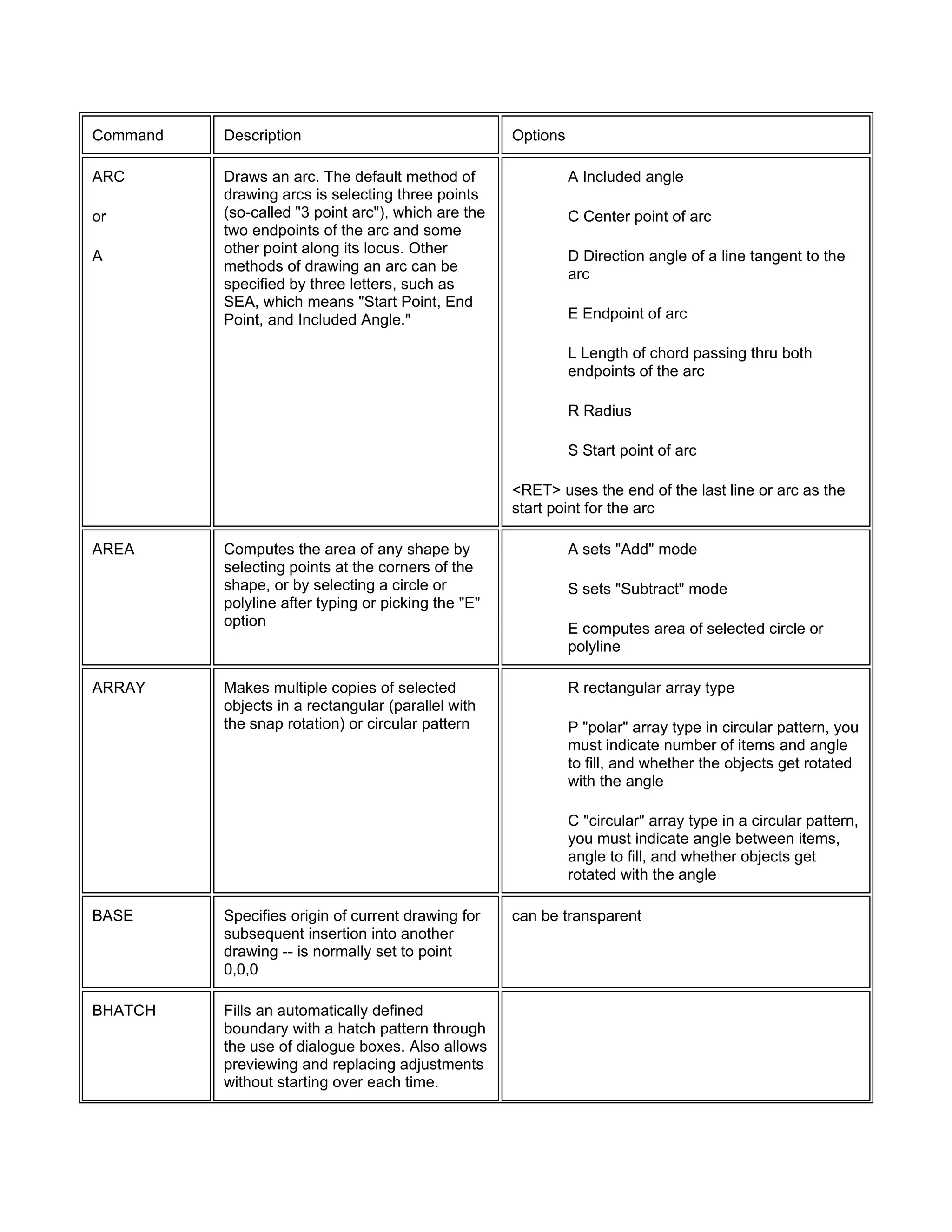
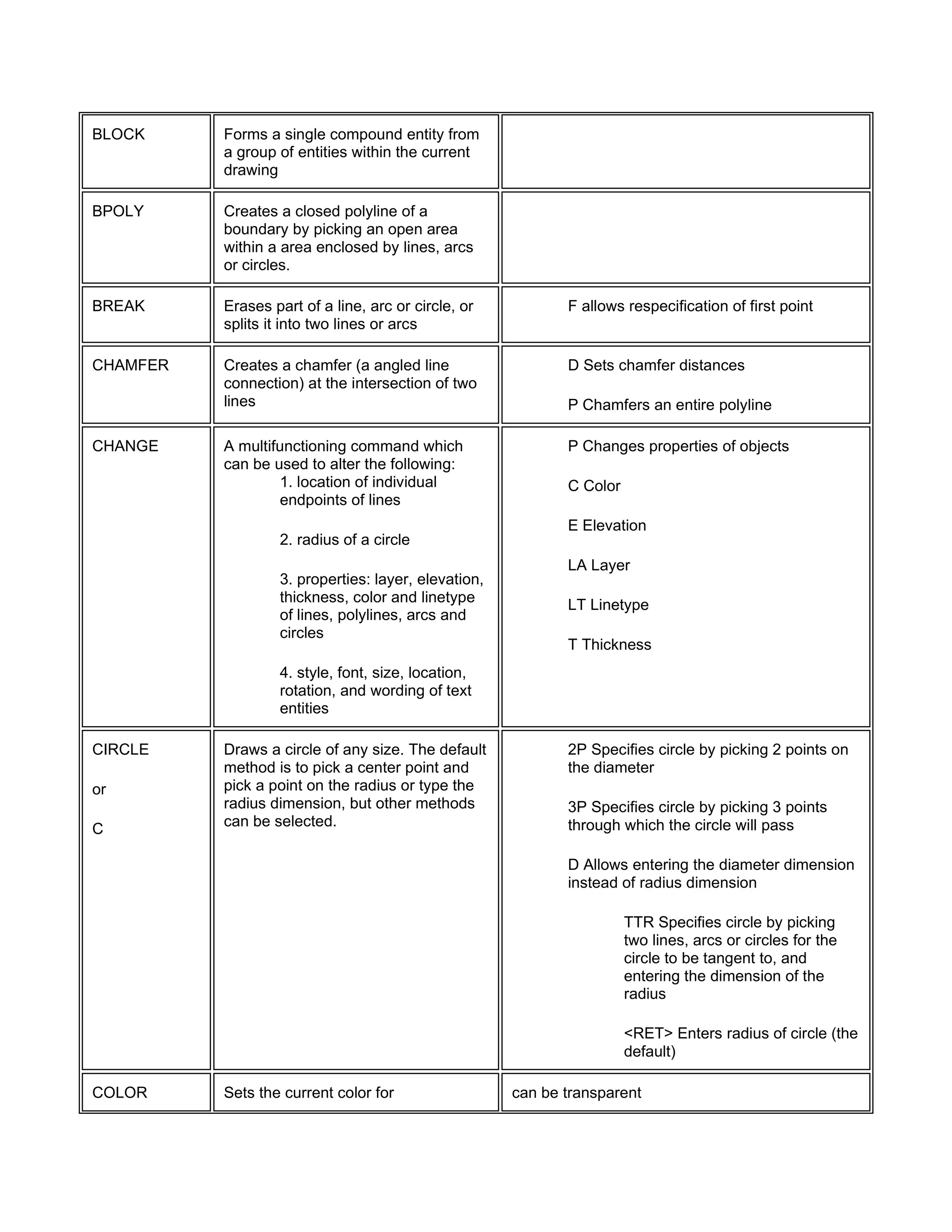
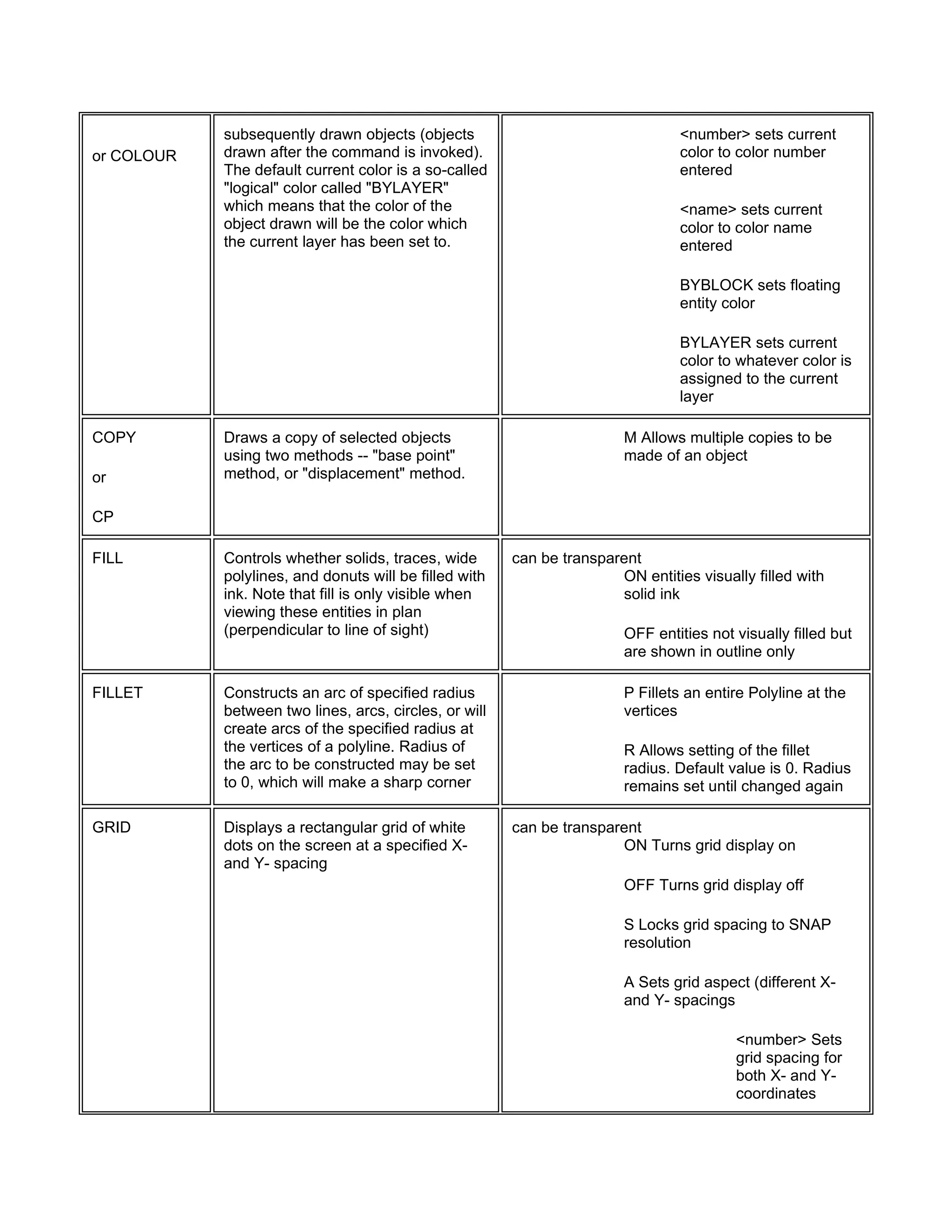
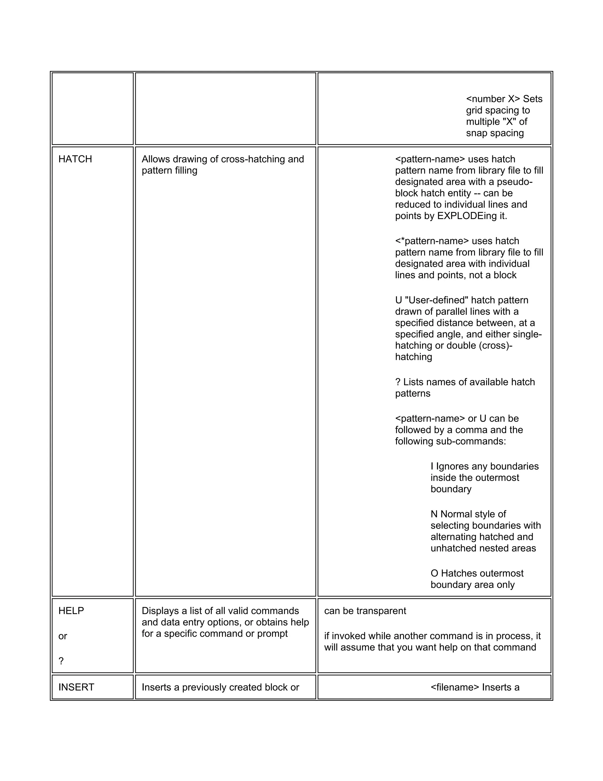
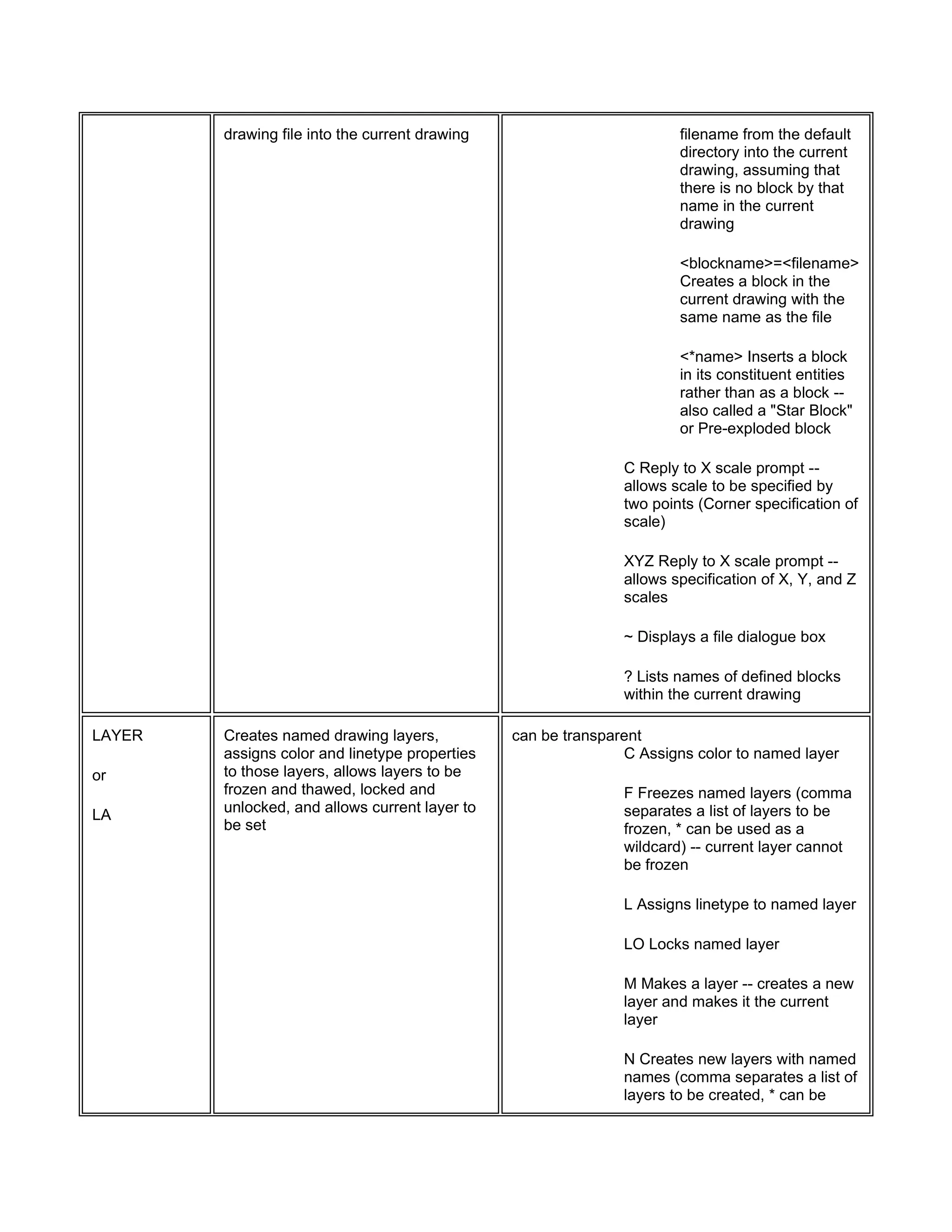
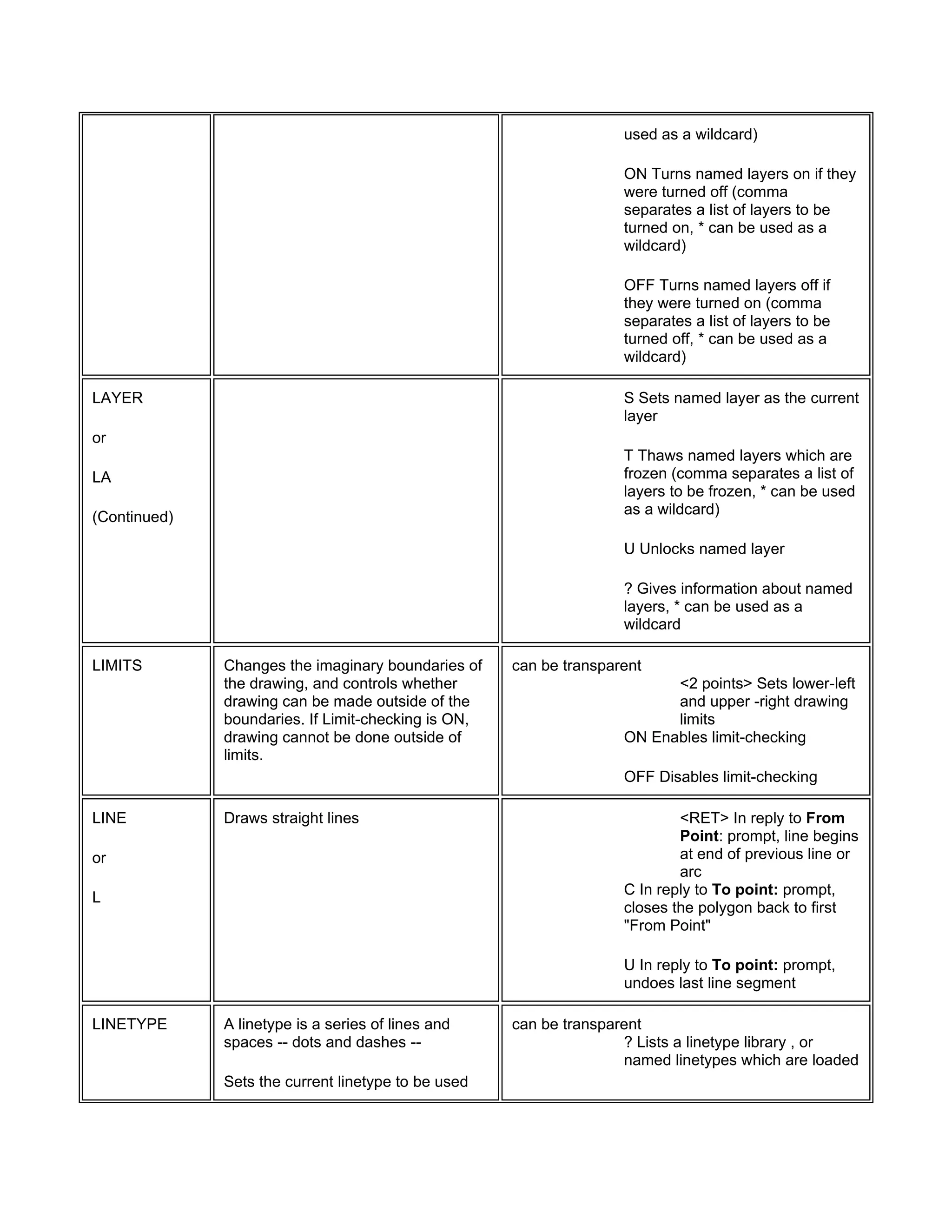
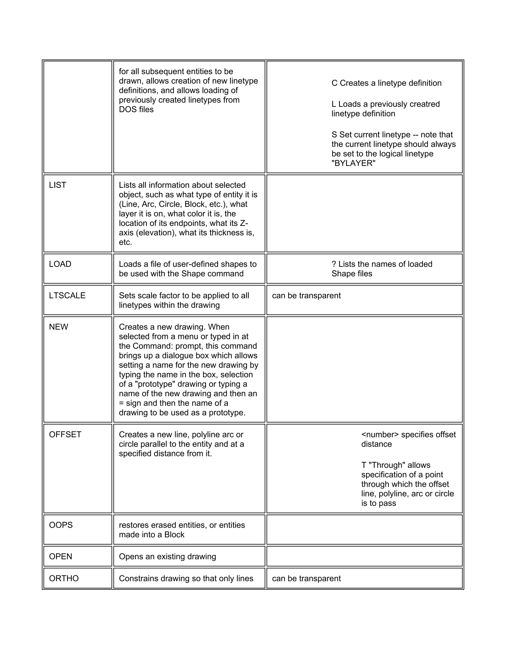
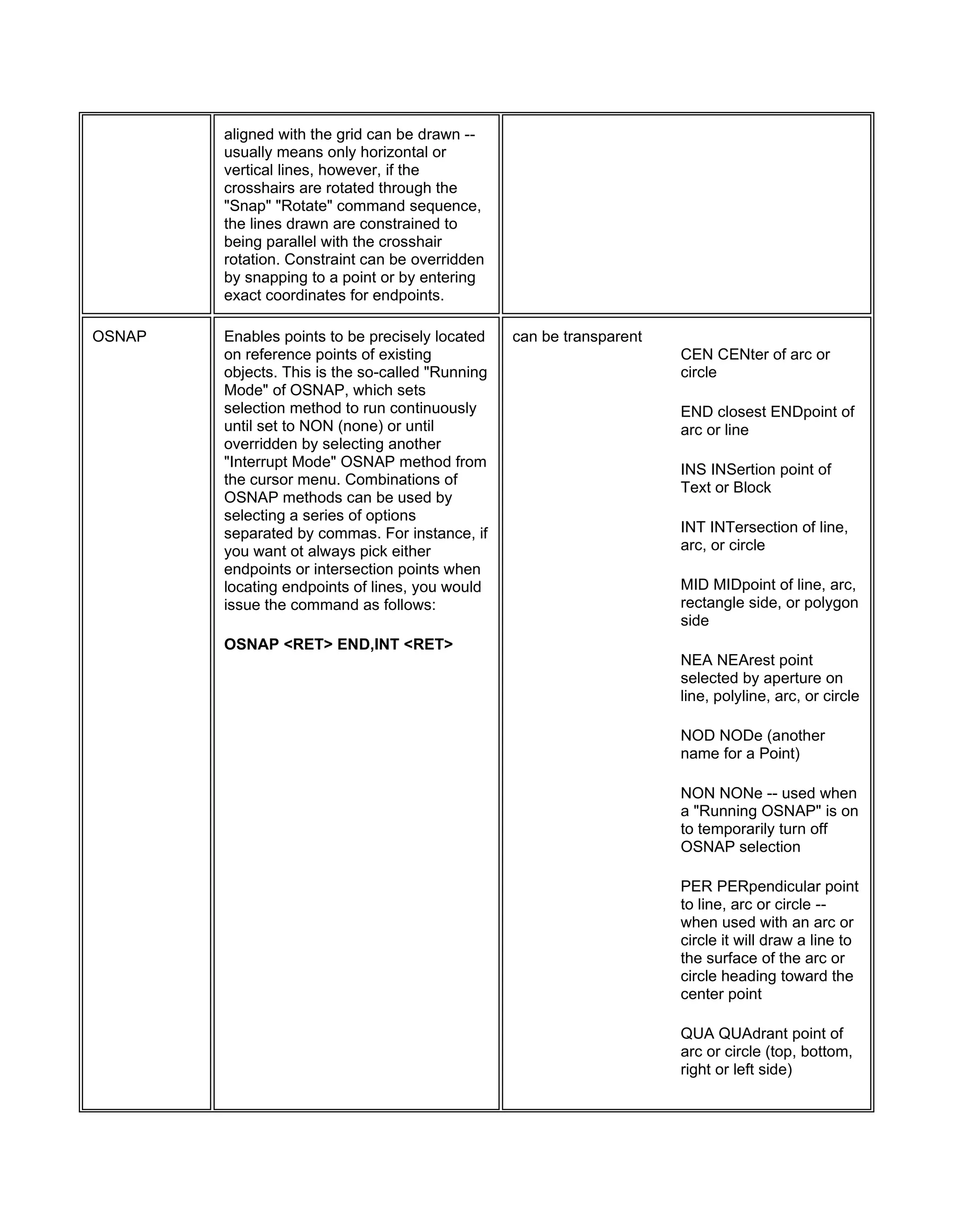
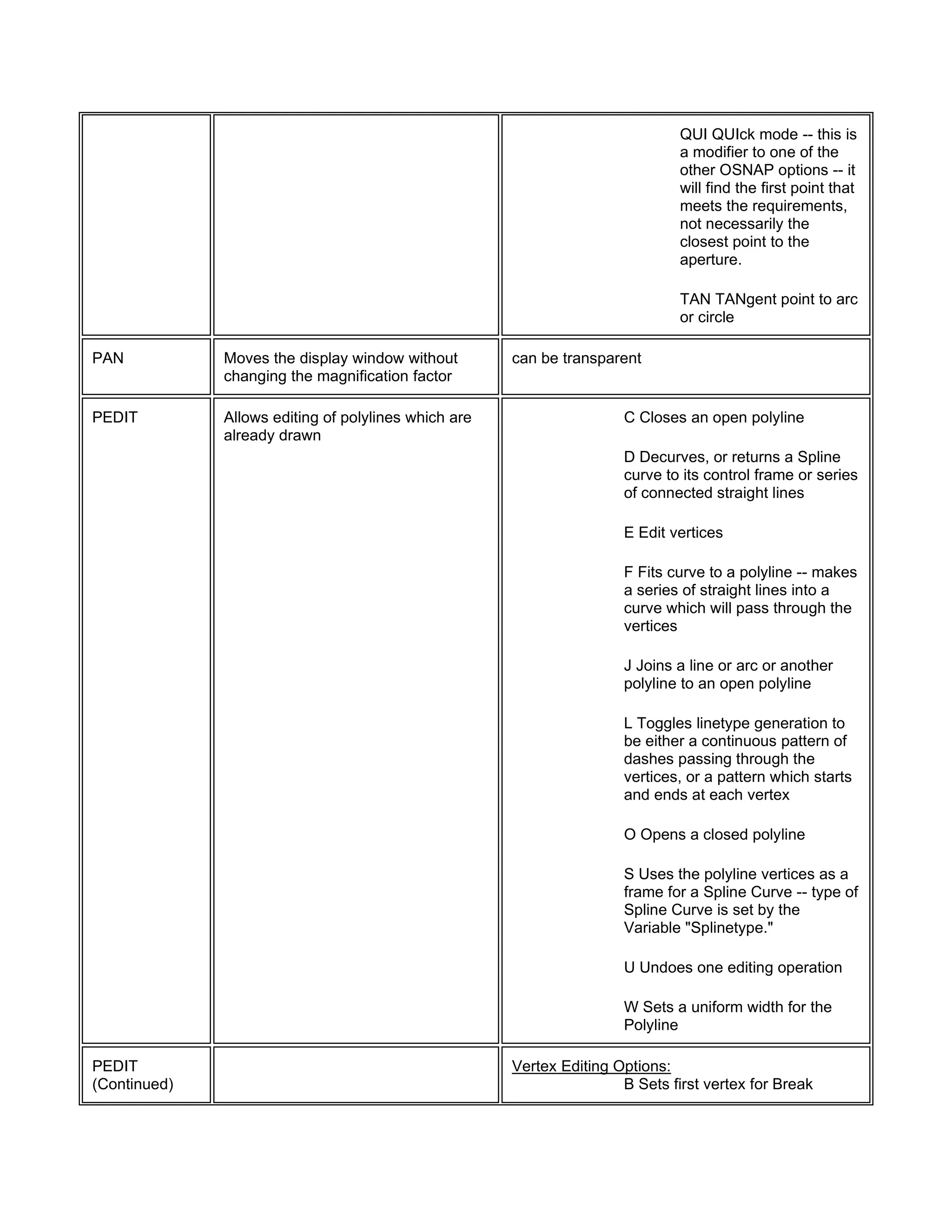
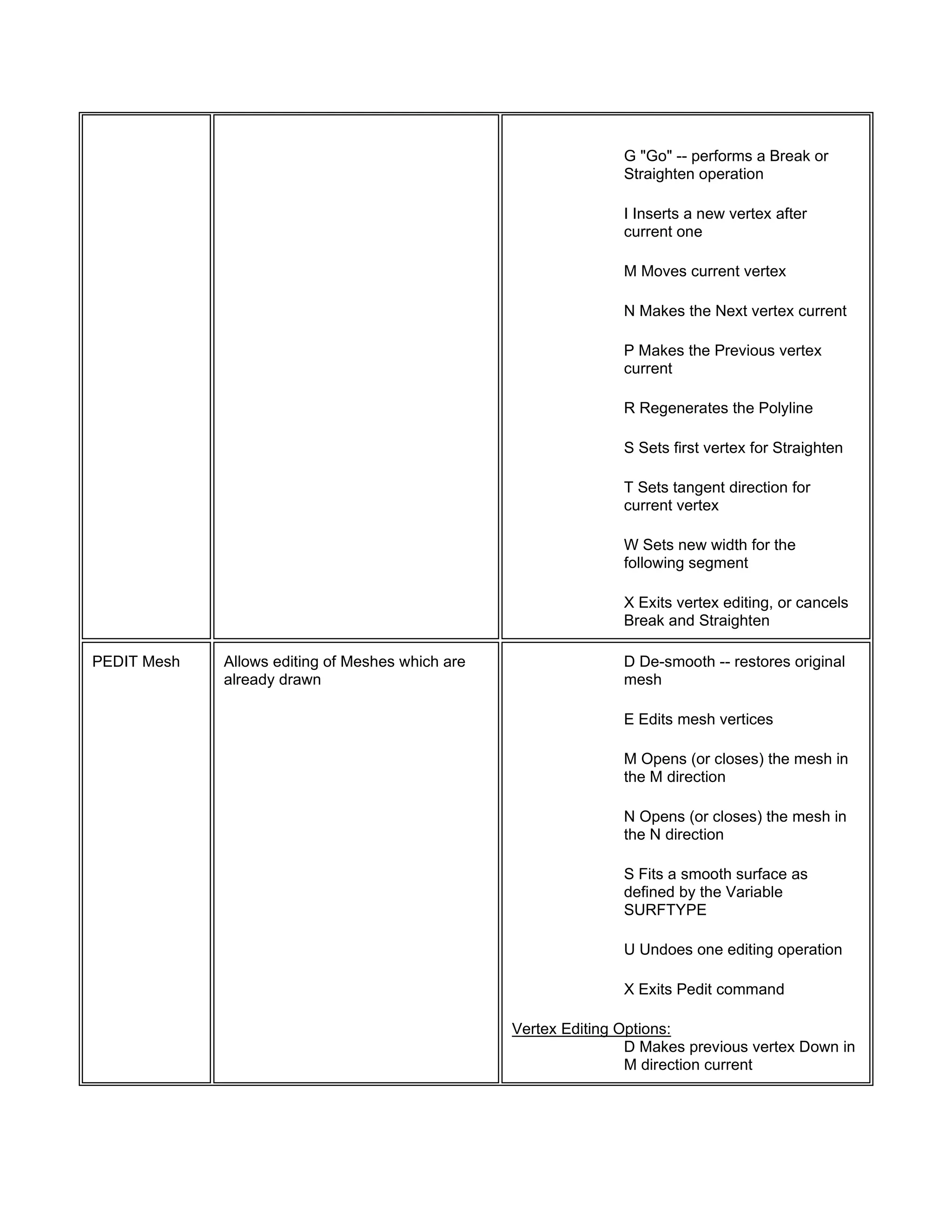
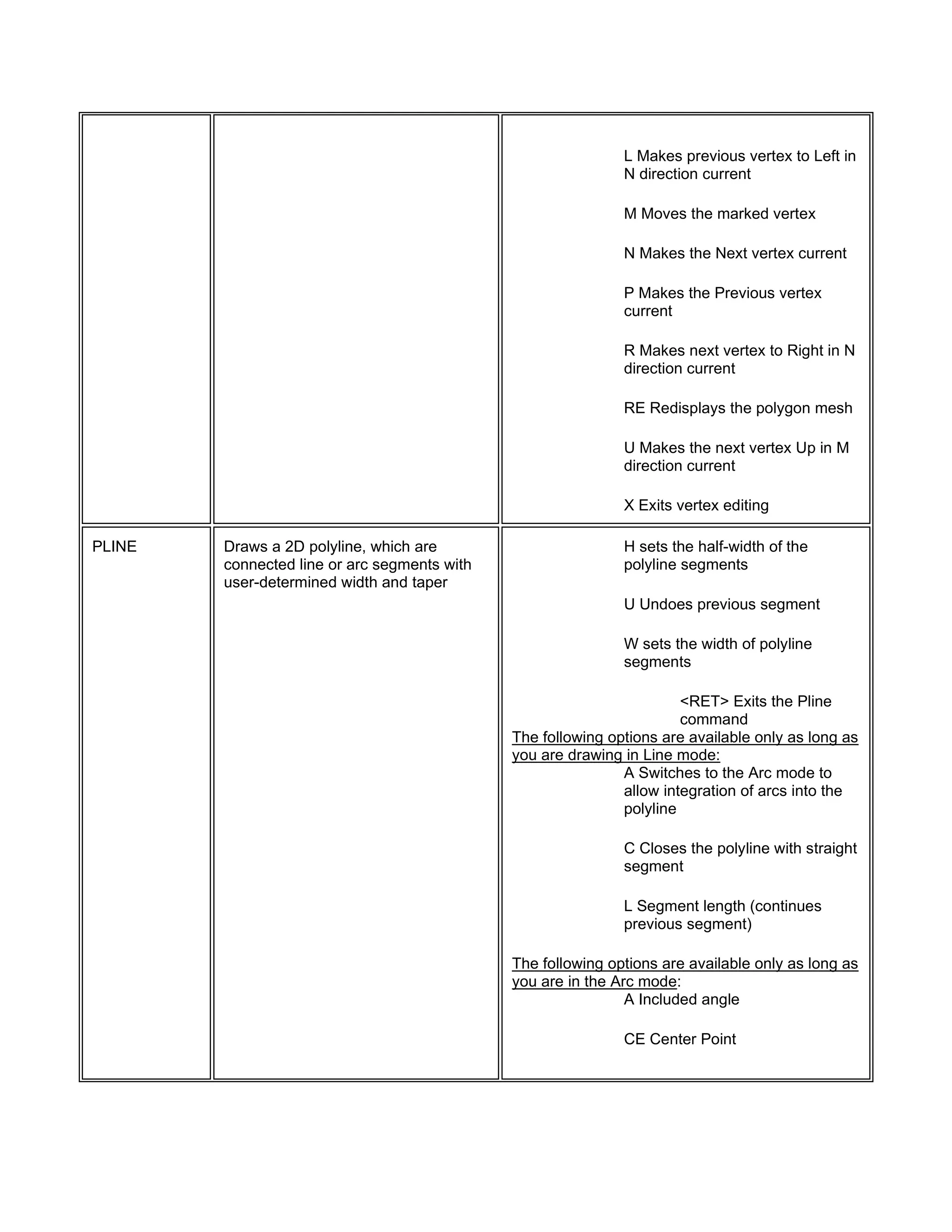
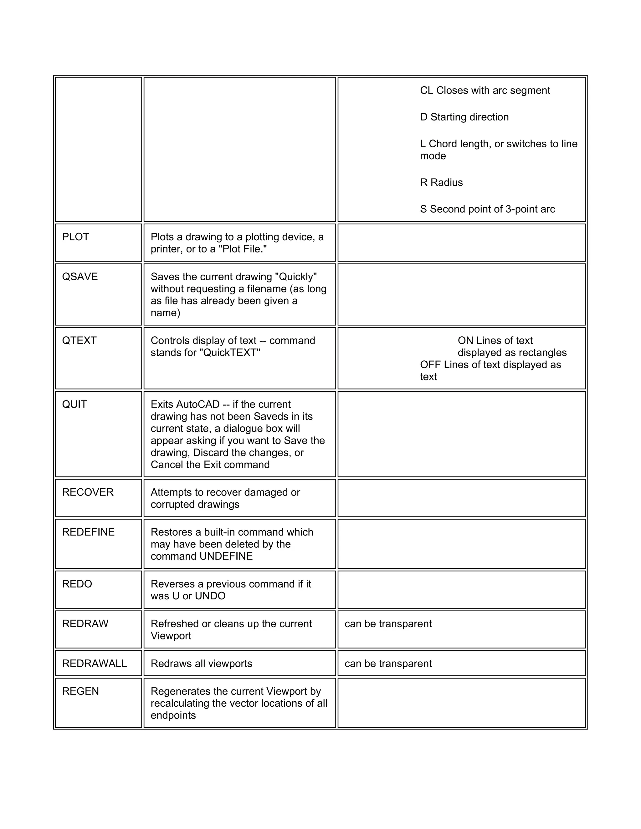
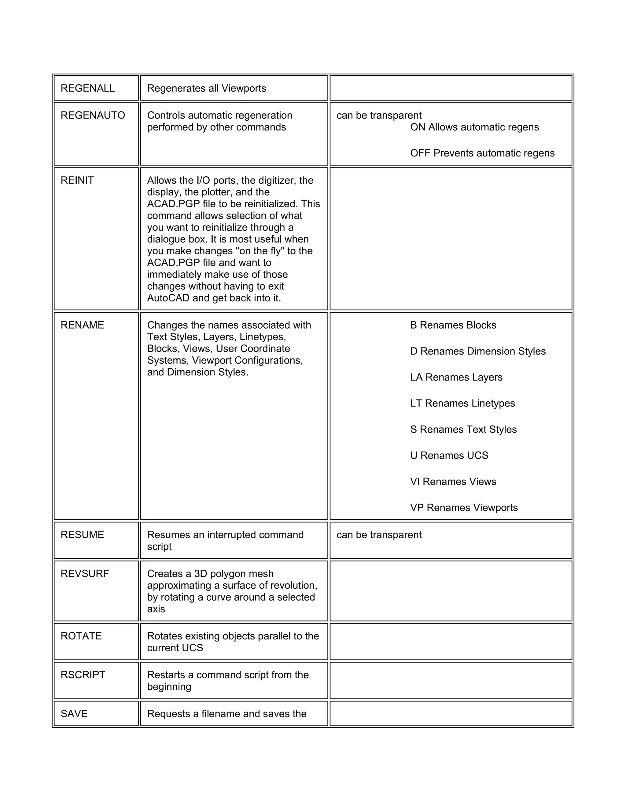
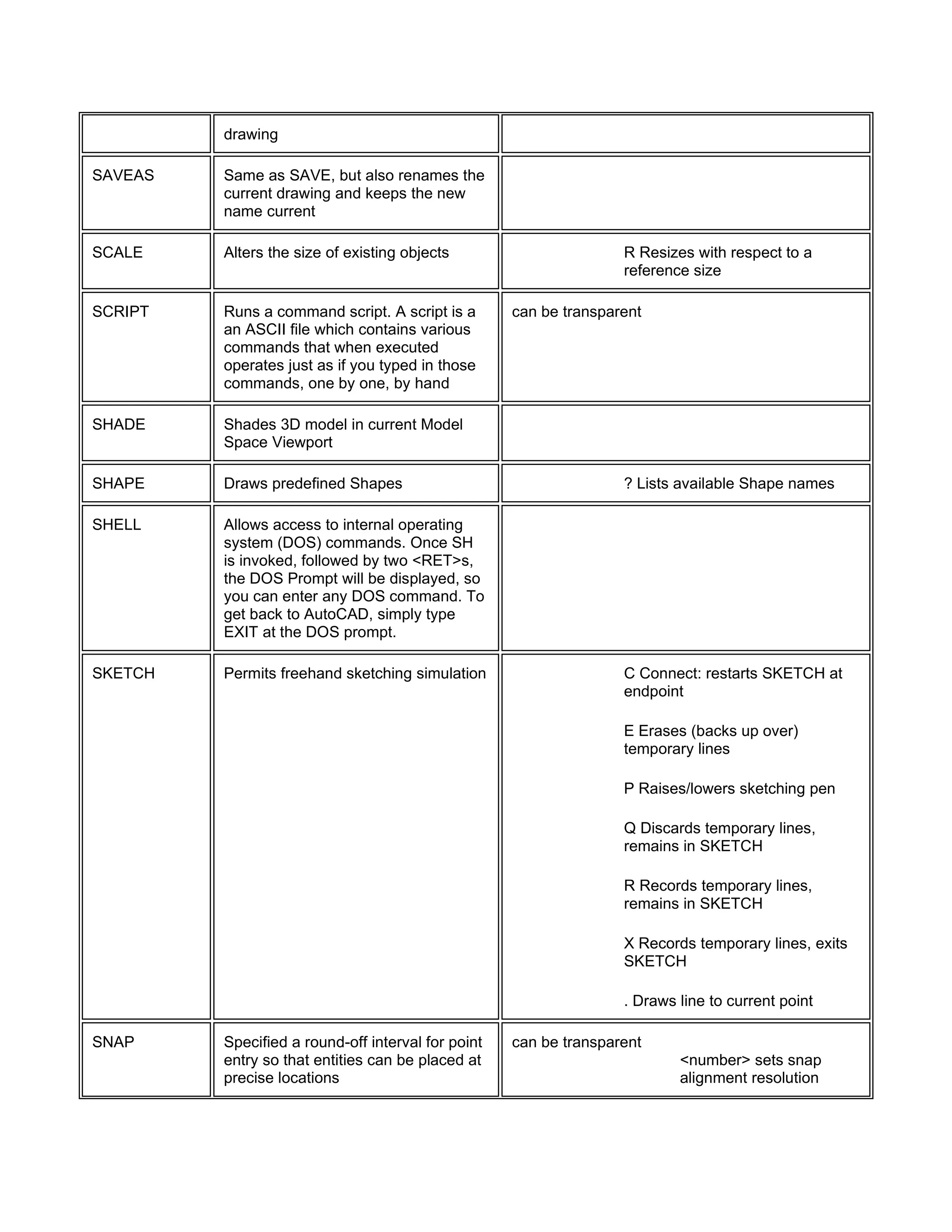
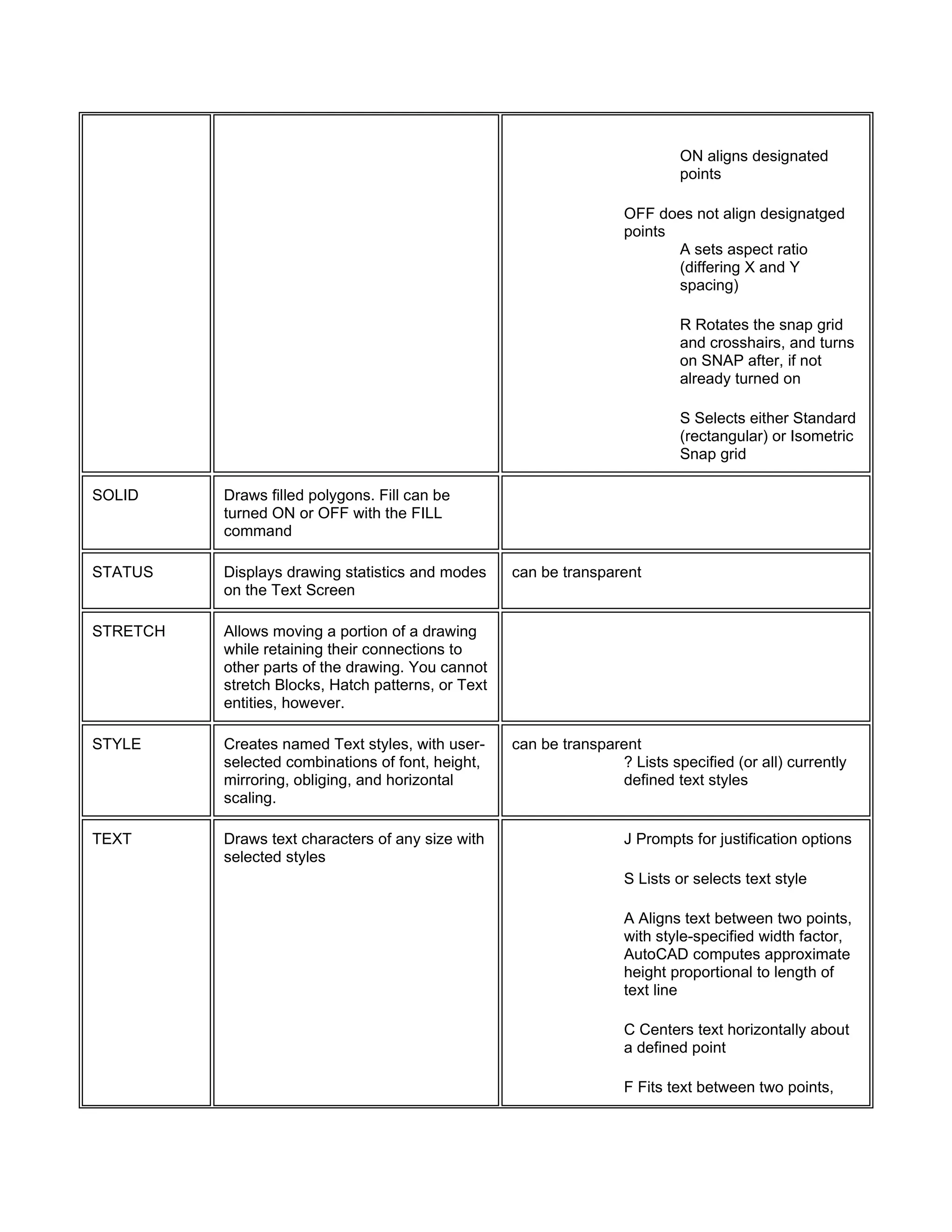
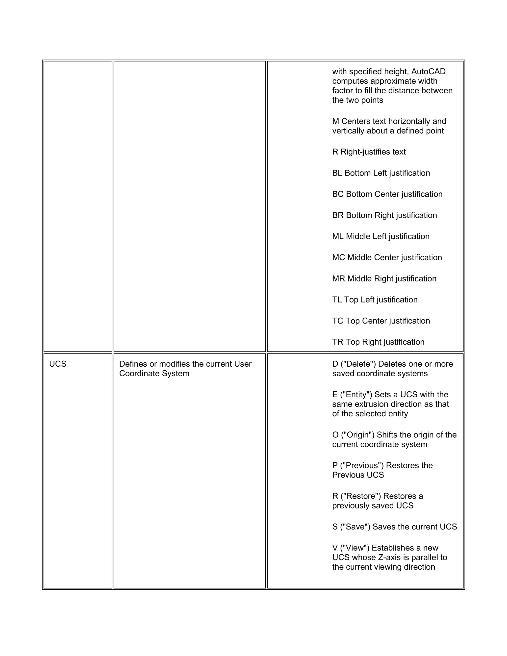
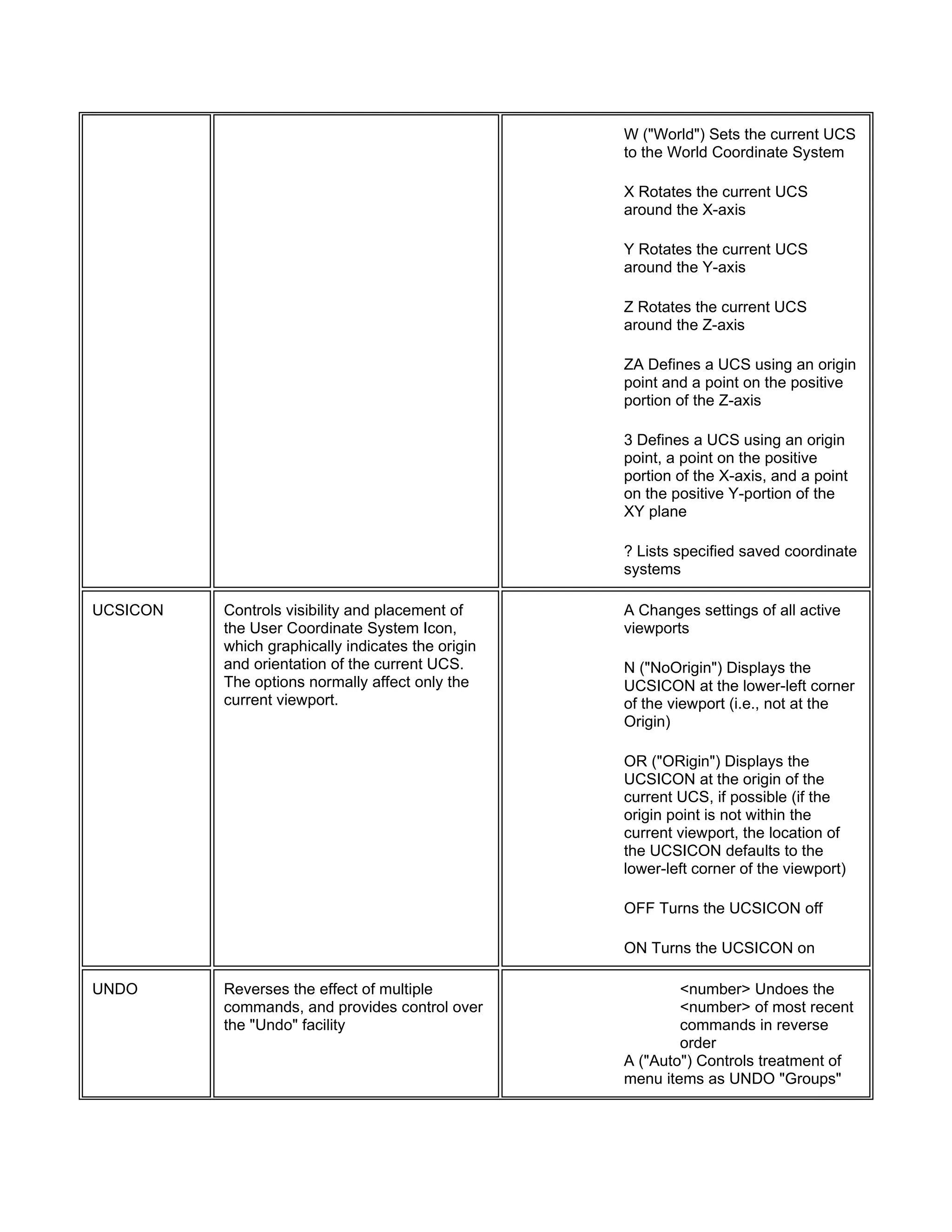
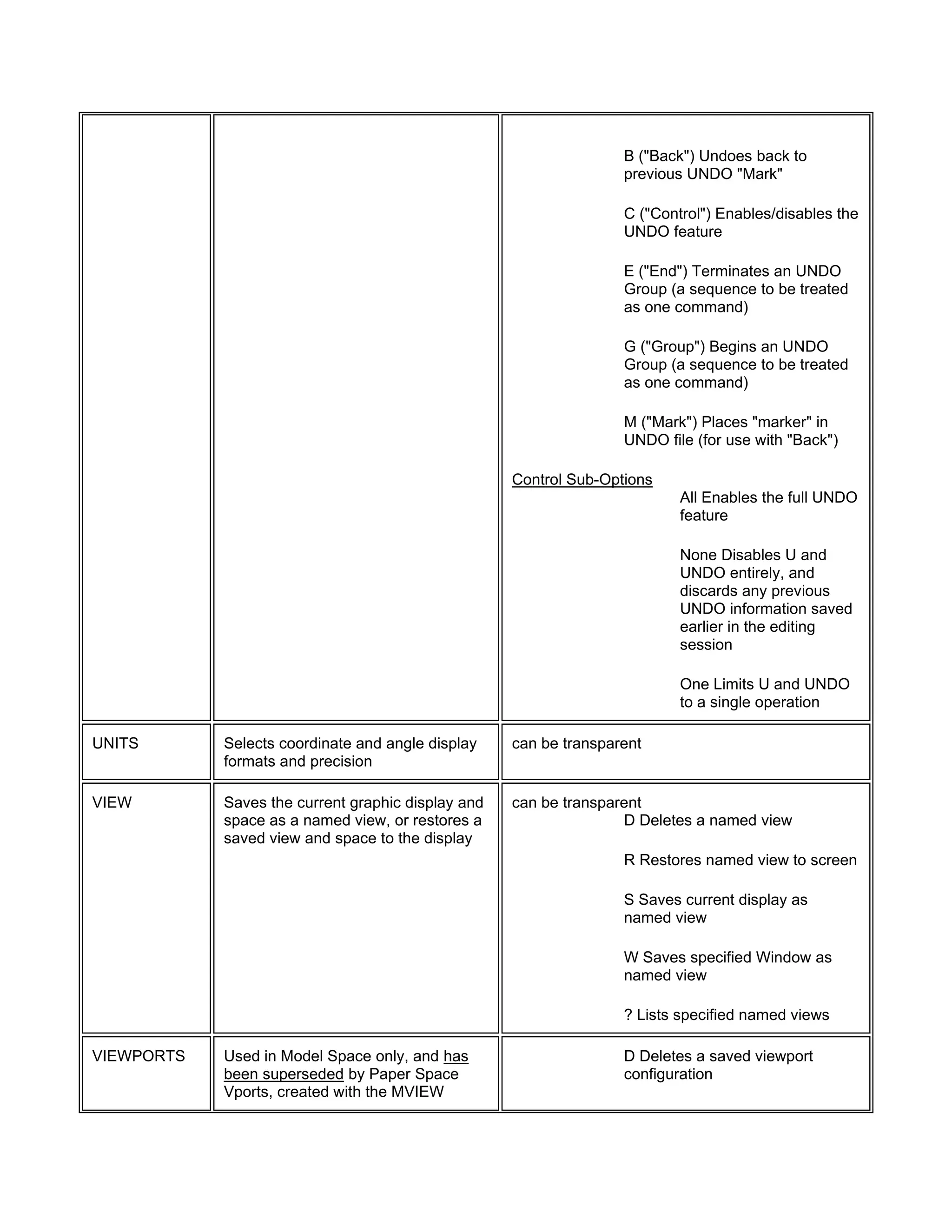
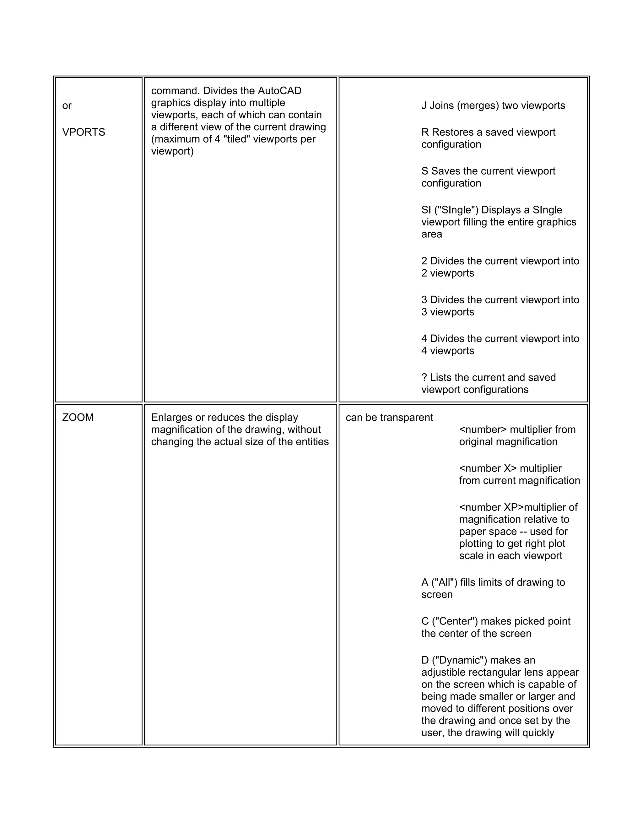
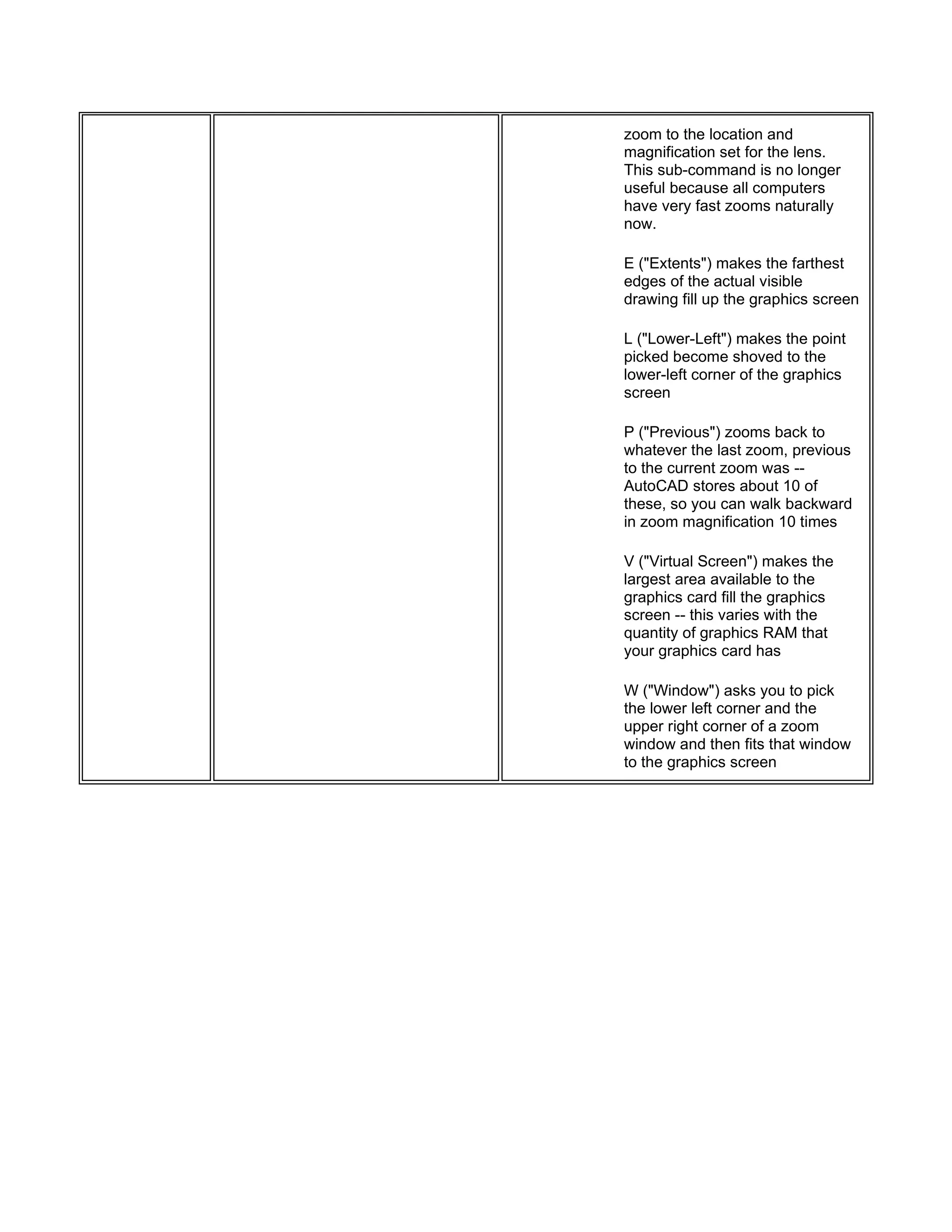
Command Description Options
ARC
or
A
Draws an arc. The default method of
drawing arcs is selecting three points
(so-called "3 point arc"), which are the
two endpoints of the arc and some
other point along its locus. Other
methods of drawing an arc can be
specified by three letters, such as
SEA, which means "Start Point, End
Point, and Included Angle."
A Included angle
C Center point of arc
D Direction angle of a line tangent to the
arc
E Endpoint of arc
L Length of chord passing thru both
endpoints of the arc
R Radius
S Start point of arc
<RET> uses the end of the last line or arc as the
start point for the arc
AREA Computes the area of any shape by
selecting points at the corners of the
shape, or by selecting a circle or
polyline after typing or picking the "E"
option
A sets "Add" mode
S sets "Subtract" mode
E computes area of selected circle or
polyline
ARRAY Makes multiple copies of selected
objects in a rectangular (parallel with
the snap rotation) or circular pattern
R rectangular array type
P "polar" array type in circular pattern, you
must indicate number of items and angle
to fill, and whether the objects get rotated
with the angle
C "circular" array type in a circular pattern,
you must indicate angle between items,
angle to fill, and whether objects get
rotated with the angle
BASE Specifies origin of current drawing for
subsequent insertion into another
drawing -- is normally set to point
0,0,0
can be transparent
BHATCH Fills an automatically defined
boundary with a hatch pattern through
the use of dialogue boxes. Also allows
previewing and replacing adjustments
without starting over each time.
BLOCK Forms a single compound entity from
a group of entities within the current
drawing
BPOLY Creates a closed polyline of a
boundary by picking an open area
within a area enclosed by lines, arcs
or circles.
BREAK Erases part of a line, arc or circle, or
splits it into two lines or arcs
F allows respecification of first point
CHAMFER Creates a chamfer (a angled line
connection) at the intersection of two
lines
D Sets chamfer distances
P Chamfers an entire polyline
CHANGE A multifunctioning command which
can be used to alter the following:
1. location of individual
endpoints of lines
2. radius of a circle
3. properties: layer, elevation,
thickness, color and linetype
of lines, polylines, arcs and
circles
4. style, font, size, location,
rotation, and wording of text
entities
P Changes properties of objects
C Color
E Elevation
LA Layer
LT Linetype
T Thickness
CIRCLE
or
C
Draws a circle of any size. The default
method is to pick a center point and
pick a point on the radius or type the
radius dimension, but other methods
can be selected.
2P Specifies circle by picking 2 points on
the diameter
3P Specifies circle by picking 3 points
through which the circle will pass
D Allows entering the diameter dimension
instead of radius dimension
TTR Specifies circle by picking
two lines, arcs or circles for the
circle to be tangent to, and
entering the dimension of the
radius
<RET> Enters radius of circle (the
default)
COLOR Sets the current color for can be transparent
or COLOUR
subsequently drawn objects (objects
drawn after the command is invoked).
The default current color is a so-called
"logical" color called "BYLAYER"
which means that the color of the
object drawn will be the color which
the current layer has been set to.
<number> sets current
color to color number
entered
<name> sets current
color to color name
entered
BYBLOCK sets floating
entity color
BYLAYER sets current
color to whatever color is
assigned to the current
layer
COPY
or
CP
Draws a copy of selected objects
using two methods -- "base point"
method, or "displacement" method.
M Allows multiple copies to be
made of an object
FILL Controls whether solids, traces, wide
polylines, and donuts will be filled with
ink. Note that fill is only visible when
viewing these entities in plan
(perpendicular to line of sight)
can be transparent
ON entities visually filled with
solid ink
OFF entities not visually filled but
are shown in outline only
FILLET Constructs an arc of specified radius
between two lines, arcs, circles, or will
create arcs of the specified radius at
the vertices of a polyline. Radius of
the arc to be constructed may be set
to 0, which will make a sharp corner
P Fillets an entire Polyline at the
vertices
R Allows setting of the fillet
radius. Default value is 0. Radius
remains set until changed again
GRID Displays a rectangular grid of white
dots on the screen at a specified X-
and Y- spacing
can be transparent
ON Turns grid display on
OFF Turns grid display off
S Locks grid spacing to SNAP
resolution
A Sets grid aspect (different X-
and Y- spacings
<number> Sets
grid spacing for
both X- and Y-
coordinates
<number X> Sets
grid spacing to
multiple "X" of
snap spacing
HATCH Allows drawing of cross-hatching and
pattern filling
<pattern-name> uses hatch
pattern name from library file to fill
designated area with a pseudo-
block hatch entity -- can be
reduced to individual lines and
points by EXPLODEing it.
<*pattern-name> uses hatch
pattern name from library file to fill
designated area with individual
lines and points, not a block
U "User-defined" hatch pattern
drawn of parallel lines with a
specified distance between, at a
specified angle, and either single-
hatching or double (cross)-
hatching
? Lists names of available hatch
patterns
<pattern-name> or U can be
followed by a comma and the
following sub-commands:
I Ignores any boundaries
inside the outermost
boundary
N Normal style of
selecting boundaries with
alternating hatched and
unhatched nested areas
O Hatches outermost
boundary area only
HELP
or
?
Displays a list of all valid commands
and data entry options, or obtains help
for a specific command or prompt
can be transparent
if invoked while another command is in process, it
will assume that you want help on that command
INSERT Inserts a previously created block or <filename> Inserts a
drawing file into the current drawing filename from the default
directory into the current
drawing, assuming that
there is no block by that
name in the current
drawing
<blockname>=<filename>
Creates a block in the
current drawing with the
same name as the file
<*name> Inserts a block
in its constituent entities
rather than as a block --
also called a "Star Block"
or Pre-exploded block
C Reply to X scale prompt --
allows scale to be specified by
two points (Corner specification of
scale)
XYZ Reply to X scale prompt --
allows specification of X, Y, and Z
scales
~ Displays a file dialogue box
? Lists names of defined blocks
within the current drawing
LAYER
or
LA
Creates named drawing layers,
assigns color and linetype properties
to those layers, allows layers to be
frozen and thawed, locked and
unlocked, and allows current layer to
be set
can be transparent
C Assigns color to named layer
F Freezes named layers (comma
separates a list of layers to be
frozen, * can be used as a
wildcard) -- current layer cannot
be frozen
L Assigns linetype to named layer
LO Locks named layer
M Makes a layer -- creates a new
layer and makes it the current
layer
N Creates new layers with named
names (comma separates a list of
layers to be created, * can be
used as a wildcard)
ON Turns named layers on if they
were turned off (comma
separates a list of layers to be
turned on, * can be used as a
wildcard)
OFF Turns named layers off if
they were turned on (comma
separates a list of layers to be
turned off, * can be used as a
wildcard)
LAYER
or
LA
(Continued)
S Sets named layer as the current
layer
T Thaws named layers which are
frozen (comma separates a list of
layers to be frozen, * can be used
as a wildcard)
U Unlocks named layer
? Gives information about named
layers, * can be used as a
wildcard
LIMITS Changes the imaginary boundaries of
the drawing, and controls whether
drawing can be made outside of the
boundaries. If Limit-checking is ON,
drawing cannot be done outside of
limits.
can be transparent
<2 points> Sets lower-left
and upper -right drawing
limits
ON Enables limit-checking
OFF Disables limit-checking
LINE
or
L
Draws straight lines <RET> In reply to From
Point: prompt, line begins
at end of previous line or
arc
C In reply to To point: prompt,
closes the polygon back to first
"From Point"
U In reply to To point: prompt,
undoes last line segment
LINETYPE A linetype is a series of lines and
spaces -- dots and dashes --
Sets the current linetype to be used
can be transparent
? Lists a linetype library , or
named linetypes which are loaded
for all subsequent entities to be
drawn, allows creation of new linetype
definitions, and allows loading of
previously created linetypes from
DOS files
C Creates a linetype definition
L Loads a previously creatred
linetype definition
S Set current linetype -- note that
the current linetype should always
be set to the logical linetype
"BYLAYER"
LIST Lists all information about selected
object, such as what type of entity it is
(Line, Arc, Circle, Block, etc.), what
layer it is on, what color it is, the
location of its endpoints, what its Z-
axis (elevation), what its thickness is,
etc.
LOAD Loads a file of user-defined shapes to
be used with the Shape command
? Lists the names of loaded
Shape files
LTSCALE Sets scale factor to be applied to all
linetypes within the drawing
can be transparent
NEW Creates a new drawing. When
selected from a menu or typed in at
the Command: prompt, this command
brings up a dialogue box which allows
setting a name for the new drawing by
typing the name in the box, selection
of a "prototype" drawing or typing a
name of the new drawing and then an
= sign and then the name of a
drawing to be used as a prototype.
OFFSET Creates a new line, polyline arc or
circle parallel to the entity and at a
specified distance from it.
<number> specifies offset
distance
T "Through" allows
specification of a point
through which the offset
line, polyline, arc or circle
is to pass
OOPS restores erased entities, or entities
made into a Block
OPEN Opens an existing drawing
ORTHO Constrains drawing so that only lines can be transparent
aligned with the grid can be drawn --
usually means only horizontal or
vertical lines, however, if the
crosshairs are rotated through the
"Snap" "Rotate" command sequence,
the lines drawn are constrained to
being parallel with the crosshair
rotation. Constraint can be overridden
by snapping to a point or by entering
exact coordinates for endpoints.
OSNAP Enables points to be precisely located
on reference points of existing
objects. This is the so-called "Running
Mode" of OSNAP, which sets
selection method to run continuously
until set to NON (none) or until
overridden by selecting another
"Interrupt Mode" OSNAP method from
the cursor menu. Combinations of
OSNAP methods can be used by
selecting a series of options
separated by commas. For instance, if
you want ot always pick either
endpoints or intersection points when
locating endpoints of lines, you would
issue the command as follows:
OSNAP <RET> END,INT <RET>
can be transparent
CEN CENter of arc or
circle
END closest ENDpoint of
arc or line
INS INSertion point of
Text or Block
INT INTersection of line,
arc, or circle
MID MIDpoint of line, arc,
rectangle side, or polygon
side
NEA NEArest point
selected by aperture on
line, polyline, arc, or circle
NOD NODe (another
name for a Point)
NON NONe -- used when
a "Running OSNAP" is on
to temporarily turn off
OSNAP selection
PER PERpendicular point
to line, arc or circle --
when used with an arc or
circle it will draw a line to
the surface of the arc or
circle heading toward the
center point
QUA QUAdrant point of
arc or circle (top, bottom,
right or left side)
QUI QUIck mode -- this is
a modifier to one of the
other OSNAP options -- it
will find the first point that
meets the requirements,
not necessarily the
closest point to the
aperture.
TAN TANgent point to arc
or circle
PAN Moves the display window without
changing the magnification factor
can be transparent
PEDIT Allows editing of polylines which are
already drawn
C Closes an open polyline
D Decurves, or returns a Spline
curve to its control frame or series
of connected straight lines
E Edit vertices
F Fits curve to a polyline -- makes
a series of straight lines into a
curve which will pass through the
vertices
J Joins a line or arc or another
polyline to an open polyline
L Toggles linetype generation to
be either a continuous pattern of
dashes passing through the
vertices, or a pattern which starts
and ends at each vertex
O Opens a closed polyline
S Uses the polyline vertices as a
frame for a Spline Curve -- type of
Spline Curve is set by the
Variable "Splinetype."
U Undoes one editing operation
W Sets a uniform width for the
Polyline
PEDIT
(Continued)
Vertex Editing Options:
B Sets first vertex for Break
G "Go" -- performs a Break or
Straighten operation
I Inserts a new vertex after
current one
M Moves current vertex
N Makes the Next vertex current
P Makes the Previous vertex
current
R Regenerates the Polyline
S Sets first vertex for Straighten
T Sets tangent direction for
current vertex
W Sets new width for the
following segment
X Exits vertex editing, or cancels
Break and Straighten
PEDIT Mesh Allows editing of Meshes which are
already drawn
D De-smooth -- restores original
mesh
E Edits mesh vertices
M Opens (or closes) the mesh in
the M direction
N Opens (or closes) the mesh in
the N direction
S Fits a smooth surface as
defined by the Variable
SURFTYPE
U Undoes one editing operation
X Exits Pedit command
Vertex Editing Options:
D Makes previous vertex Down in
M direction current
L Makes previous vertex to Left in
N direction current
M Moves the marked vertex
N Makes the Next vertex current
P Makes the Previous vertex
current
R Makes next vertex to Right in N
direction current
RE Redisplays the polygon mesh
U Makes the next vertex Up in M
direction current
X Exits vertex editing
PLINE Draws a 2D polyline, which are
connected line or arc segments with
user-determined width and taper
H sets the half-width of the
polyline segments
U Undoes previous segment
W sets the width of polyline
segments
<RET> Exits the Pline
command
The following options are available only as long as
you are drawing in Line mode:
A Switches to the Arc mode to
allow integration of arcs into the
polyline
C Closes the polyline with straight
segment
L Segment length (continues
previous segment)
The following options are available only as long as
you are in the Arc mode:
A Included angle
CE Center Point
CL Closes with arc segment
D Starting direction
L Chord length, or switches to line
mode
R Radius
S Second point of 3-point arc
PLOT Plots a drawing to a plotting device, a
printer, or to a "Plot File."
QSAVE Saves the current drawing "Quickly"
without requesting a filename (as long
as file has already been given a
name)
QTEXT Controls display of text -- command
stands for "QuickTEXT"
ON Lines of text
displayed as rectangles
OFF Lines of text displayed as
text
QUIT Exits AutoCAD -- if the current
drawing has not been Saveds in its
current state, a dialogue box will
appear asking if you want to Save the
drawing, Discard the changes, or
Cancel the Exit command
RECOVER Attempts to recover damaged or
corrupted drawings
REDEFINE Restores a built-in command which
may have been deleted by the
command UNDEFINE
REDO Reverses a previous command if it
was U or UNDO
REDRAW Refreshed or cleans up the current
Viewport
can be transparent
REDRAWALL Redraws all viewports can be transparent
REGEN Regenerates the current Viewport by
recalculating the vector locations of all
endpoints
REGENALL Regenerates all Viewports
REGENAUTO Controls automatic regeneration
performed by other commands
can be transparent
ON Allows automatic regens
OFF Prevents automatic regens
REINIT Allows the I/O ports, the digitizer, the
display, the plotter, and the
ACAD.PGP file to be reinitialized. This
command allows selection of what
you want to reinitialize through a
dialogue box. It is most useful when
you make changes "on the fly" to the
ACAD.PGP file and want to
immediately make use of those
changes without having to exit
AutoCAD and get back into it.
RENAME Changes the names associated with
Text Styles, Layers, Linetypes,
Blocks, Views, User Coordinate
Systems, Viewport Configurations,
and Dimension Styles.
B Renames Blocks
D Renames Dimension Styles
LA Renames Layers
LT Renames Linetypes
S Renames Text Styles
U Renames UCS
VI Renames Views
VP Renames Viewports
RESUME Resumes an interrupted command
script
can be transparent
REVSURF Creates a 3D polygon mesh
approximating a surface of revolution,
by rotating a curve around a selected
axis
ROTATE Rotates existing objects parallel to the
current UCS
RSCRIPT Restarts a command script from the
beginning
SAVE Requests a filename and saves the
drawing
SAVEAS Same as SAVE, but also renames the
current drawing and keeps the new
name current
SCALE Alters the size of existing objects R Resizes with respect to a
reference size
SCRIPT Runs a command script. A script is a
an ASCII file which contains various
commands that when executed
operates just as if you typed in those
commands, one by one, by hand
can be transparent
SHADE Shades 3D model in current Model
Space Viewport
SHAPE Draws predefined Shapes ? Lists available Shape names
SHELL Allows access to internal operating
system (DOS) commands. Once SH
is invoked, followed by two <RET>s,
the DOS Prompt will be displayed, so
you can enter any DOS command. To
get back to AutoCAD, simply type
EXIT at the DOS prompt.
SKETCH Permits freehand sketching simulation C Connect: restarts SKETCH at
endpoint
E Erases (backs up over)
temporary lines
P Raises/lowers sketching pen
Q Discards temporary lines,
remains in SKETCH
R Records temporary lines,
remains in SKETCH
X Records temporary lines, exits
SKETCH
. Draws line to current point
SNAP Specified a round-off interval for point
entry so that entities can be placed at
precise locations
can be transparent
<number> sets snap
alignment resolution
ON aligns designated
points
OFF does not align designatged
points
A sets aspect ratio
(differing X and Y
spacing)
R Rotates the snap grid
and crosshairs, and turns
on SNAP after, if not
already turned on
S Selects either Standard
(rectangular) or Isometric
Snap grid
SOLID Draws filled polygons. Fill can be
turned ON or OFF with the FILL
command
STATUS Displays drawing statistics and modes
on the Text Screen
can be transparent
STRETCH Allows moving a portion of a drawing
while retaining their connections to
other parts of the drawing. You cannot
stretch Blocks, Hatch patterns, or Text
entities, however.
STYLE Creates named Text styles, with user-
selected combinations of font, height,
mirroring, obliging, and horizontal
scaling.
can be transparent
? Lists specified (or all) currently
defined text styles
TEXT Draws text characters of any size with
selected styles
J Prompts for justification options
S Lists or selects text style
A Aligns text between two points,
with style-specified width factor,
AutoCAD computes approximate
height proportional to length of
text line
C Centers text horizontally about
a defined point
F Fits text between two points,
with specified height, AutoCAD
computes approximate width
factor to fill the distance between
the two points
M Centers text horizontally and
vertically about a defined point
R Right-justifies text
BL Bottom Left justification
BC Bottom Center justification
BR Bottom Right justification
ML Middle Left justification
MC Middle Center justification
MR Middle Right justification
TL Top Left justification
TC Top Center justification
TR Top Right justification
UCS Defines or modifies the current User
Coordinate System
D ("Delete") Deletes one or more
saved coordinate systems
E ("Entity") Sets a UCS with the
same extrusion direction as that
of the selected entity
O ("Origin") Shifts the origin of the
current coordinate system
P ("Previous") Restores the
Previous UCS
R ("Restore") Restores a
previously saved UCS
S ("Save") Saves the current UCS
V ("View") Establishes a new
UCS whose Z-axis is parallel to
the current viewing direction
W ("World") Sets the current UCS
to the World Coordinate System
X Rotates the current UCS
around the X-axis
Y Rotates the current UCS
around the Y-axis
Z Rotates the current UCS
around the Z-axis
ZA Defines a UCS using an origin
point and a point on the positive
portion of the Z-axis
3 Defines a UCS using an origin
point, a point on the positive
portion of the X-axis, and a point
on the positive Y-portion of the
XY plane
? Lists specified saved coordinate
systems
UCSICON Controls visibility and placement of
the User Coordinate System Icon,
which graphically indicates the origin
and orientation of the current UCS.
The options normally affect only the
current viewport.
A Changes settings of all active
viewports
N ("NoOrigin") Displays the
UCSICON at the lower-left corner
of the viewport (i.e., not at the
Origin)
OR ("ORigin") Displays the
UCSICON at the origin of the
current UCS, if possible (if the
origin point is not within the
current viewport, the location of
the UCSICON defaults to the
lower-left corner of the viewport)
OFF Turns the UCSICON off
ON Turns the UCSICON on
UNDO Reverses the effect of multiple
commands, and provides control over
the "Undo" facility
<number> Undoes the
<number> of most recent
commands in reverse
order
A ("Auto") Controls treatment of
menu items as UNDO "Groups"
B ("Back") Undoes back to
previous UNDO "Mark"
C ("Control") Enables/disables the
UNDO feature
E ("End") Terminates an UNDO
Group (a sequence to be treated
as one command)
G ("Group") Begins an UNDO
Group (a sequence to be treated
as one command)
M ("Mark") Places "marker" in
UNDO file (for use with "Back")
Control Sub-Options
All Enables the full UNDO
feature
None Disables U and
UNDO entirely, and
discards any previous
UNDO information saved
earlier in the editing
session
One Limits U and UNDO
to a single operation
UNITS Selects coordinate and angle display
formats and precision
can be transparent
VIEW Saves the current graphic display and
space as a named view, or restores a
saved view and space to the display
can be transparent
D Deletes a named view
R Restores named view to screen
S Saves current display as
named view
W Saves specified Window as
named view
? Lists specified named views
VIEWPORTS Used in Model Space only, and has
been superseded by Paper Space
Vports, created with the MVIEW
D Deletes a saved viewport
configuration
or
VPORTS
command. Divides the AutoCAD
graphics display into multiple
viewports, each of which can contain
a different view of the current drawing
(maximum of 4 "tiled" viewports per
viewport)
J Joins (merges) two viewports
R Restores a saved viewport
configuration
S Saves the current viewport
configuration
SI ("SIngle") Displays a SIngle
viewport filling the entire graphics
area
2 Divides the current viewport into
2 viewports
3 Divides the current viewport into
3 viewports
4 Divides the current viewport into
4 viewports
? Lists the current and saved
viewport configurations
ZOOM Enlarges or reduces the display
magnification of the drawing, without
changing the actual size of the entities
can be transparent
<number> multiplier from
original magnification
<number X> multiplier
from current magnification
<number XP>multiplier of
magnification relative to
paper space -- used for
plotting to get right plot
scale in each viewport
A ("All") fills limits of drawing to
screen
C ("Center") makes picked point
the center of the screen
D ("Dynamic") makes an
adjustible rectangular lens appear
on the screen which is capable of
being made smaller or larger and
moved to different positions over
the drawing and once set by the
user, the drawing will quickly
zoom to the location and
magnification set for the lens.
This sub-command is no longer
useful because all computers
have very fast zooms naturally
now.
E ("Extents") makes the farthest
edges of the actual visible
drawing fill up the graphics screen
L ("Lower-Left") makes the point
picked become shoved to the
lower-left corner of the graphics
screen
P ("Previous") zooms back to
whatever the last zoom, previous
to the current zoom was --
AutoCAD stores about 10 of
these, so you can walk backward
in zoom magnification 10 times
V ("Virtual Screen") makes the
largest area available to the
graphics card fill the graphics
screen -- this varies with the
quantity of graphics RAM that
your graphics card has
W ("Window") asks you to pick
the lower left corner and the
upper right corner of a zoom
window and then fits that window
to the graphics screen

More Related Content

Similar to Autocad Commands.pdf

Auto cad command_shortcuts
Auto cad command_shortcutsAuto cad command_shortcuts
Auto cad command_shortcutsSyazwan Hj Shah
 
archicourse cad 073
archicourse cad 073archicourse cad 073
archicourse cad 073Sudeep Singh
 
R Data Visualization Tutorial: Bar Plots
R Data Visualization Tutorial: Bar PlotsR Data Visualization Tutorial: Bar Plots
R Data Visualization Tutorial: Bar PlotsRsquared Academy
 
Chart and graphs in R programming language
Chart and graphs in R programming language Chart and graphs in R programming language
Chart and graphs in R programming language CHANDAN KUMAR
 
SQL select statement and functions
SQL select statement and functionsSQL select statement and functions
SQL select statement and functionsVikas Gupta
 
Lectures r-graphics
Lectures r-graphicsLectures r-graphics
Lectures r-graphicsetyca
 
Auto cad commed
Auto cad commedAuto cad commed
Auto cad commed4CS Lahore
 
CAD CAM Lab MANNUAL Dr.BRAU.pdf
CAD CAM Lab MANNUAL Dr.BRAU.pdfCAD CAM Lab MANNUAL Dr.BRAU.pdf
CAD CAM Lab MANNUAL Dr.BRAU.pdfRameshPinninti2
 
Lesson in Strings for C Programming Lessons
Lesson in Strings for C Programming LessonsLesson in Strings for C Programming Lessons
Lesson in Strings for C Programming LessonsJamesChristianGadian
 
C UNIT-3 PREPARED BY M V B REDDY
C UNIT-3 PREPARED BY M V B REDDYC UNIT-3 PREPARED BY M V B REDDY
C UNIT-3 PREPARED BY M V B REDDYRajeshkumar Reddy
 
String in programming language in c or c++
String in programming language in c or c++String in programming language in c or c++
String in programming language in c or c++Azeemaj101
 
Auto cad command_shortcuts
Auto cad command_shortcutsAuto cad command_shortcuts
Auto cad command_shortcutsfajil Siddiki
 

Similar to Autocad Commands.pdf (20)

Auto cad command_shortcuts
Auto cad command_shortcutsAuto cad command_shortcuts
Auto cad command_shortcuts
 
archicourse cad 073
archicourse cad 073archicourse cad 073
archicourse cad 073
 
Cad me2155-lab-manual
Cad me2155-lab-manualCad me2155-lab-manual
Cad me2155-lab-manual
 
AutoCAD Command Shortcuts
AutoCAD Command ShortcutsAutoCAD Command Shortcuts
AutoCAD Command Shortcuts
 
Lecture_3.pptx
Lecture_3.pptxLecture_3.pptx
Lecture_3.pptx
 
R Data Visualization Tutorial: Bar Plots
R Data Visualization Tutorial: Bar PlotsR Data Visualization Tutorial: Bar Plots
R Data Visualization Tutorial: Bar Plots
 
Auto cad manual
Auto cad manualAuto cad manual
Auto cad manual
 
Lab_910.pdf
Lab_910.pdfLab_910.pdf
Lab_910.pdf
 
Chart and graphs in R programming language
Chart and graphs in R programming language Chart and graphs in R programming language
Chart and graphs in R programming language
 
Plot function in R
Plot function in RPlot function in R
Plot function in R
 
SQL select statement and functions
SQL select statement and functionsSQL select statement and functions
SQL select statement and functions
 
Lectures r-graphics
Lectures r-graphicsLectures r-graphics
Lectures r-graphics
 
Auto cad commed
Auto cad commedAuto cad commed
Auto cad commed
 
CAD CAM Lab MANNUAL Dr.BRAU.pdf
CAD CAM Lab MANNUAL Dr.BRAU.pdfCAD CAM Lab MANNUAL Dr.BRAU.pdf
CAD CAM Lab MANNUAL Dr.BRAU.pdf
 
Strings and pointers
Strings and pointersStrings and pointers
Strings and pointers
 
Lesson in Strings for C Programming Lessons
Lesson in Strings for C Programming LessonsLesson in Strings for C Programming Lessons
Lesson in Strings for C Programming Lessons
 
C UNIT-3 PREPARED BY M V B REDDY
C UNIT-3 PREPARED BY M V B REDDYC UNIT-3 PREPARED BY M V B REDDY
C UNIT-3 PREPARED BY M V B REDDY
 
String in programming language in c or c++
String in programming language in c or c++String in programming language in c or c++
String in programming language in c or c++
 
Auto cad command_shortcuts
Auto cad command_shortcutsAuto cad command_shortcuts
Auto cad command_shortcuts
 
Auto cad command_shortcuts
Auto cad command_shortcutsAuto cad command_shortcuts
Auto cad command_shortcuts
 

Recently uploaded

Activity 01 - Artificial Culture (1).pdf
Activity 01 - Artificial Culture (1).pdfActivity 01 - Artificial Culture (1).pdf
Activity 01 - Artificial Culture (1).pdfciinovamais
 
Unit-IV; Professional Sales Representative (PSR).pptx
Unit-IV; Professional Sales Representative (PSR).pptxUnit-IV; Professional Sales Representative (PSR).pptx
Unit-IV; Professional Sales Representative (PSR).pptxVishalSingh1417
 
1029 - Danh muc Sach Giao Khoa 10 . pdf
1029 -  Danh muc Sach Giao Khoa 10 . pdf1029 -  Danh muc Sach Giao Khoa 10 . pdf
1029 - Danh muc Sach Giao Khoa 10 . pdfQucHHunhnh
 
Mixin Classes in Odoo 17 How to Extend Models Using Mixin Classes
Mixin Classes in Odoo 17  How to Extend Models Using Mixin ClassesMixin Classes in Odoo 17  How to Extend Models Using Mixin Classes
Mixin Classes in Odoo 17 How to Extend Models Using Mixin ClassesCeline George
 
How to Create and Manage Wizard in Odoo 17
How to Create and Manage Wizard in Odoo 17How to Create and Manage Wizard in Odoo 17
How to Create and Manage Wizard in Odoo 17Celine George
 
Introduction to Nonprofit Accounting: The Basics
Introduction to Nonprofit Accounting: The BasicsIntroduction to Nonprofit Accounting: The Basics
Introduction to Nonprofit Accounting: The BasicsTechSoup
 
The basics of sentences session 3pptx.pptx
The basics of sentences session 3pptx.pptxThe basics of sentences session 3pptx.pptx
The basics of sentences session 3pptx.pptxheathfieldcps1
 
2024-NATIONAL-LEARNING-CAMP-AND-OTHER.pptx
2024-NATIONAL-LEARNING-CAMP-AND-OTHER.pptx2024-NATIONAL-LEARNING-CAMP-AND-OTHER.pptx
2024-NATIONAL-LEARNING-CAMP-AND-OTHER.pptxMaritesTamaniVerdade
 
TỔNG ÔN TẬP THI VÀO LỚP 10 MÔN TIẾNG ANH NĂM HỌC 2023 - 2024 CÓ ĐÁP ÁN (NGỮ Â...
TỔNG ÔN TẬP THI VÀO LỚP 10 MÔN TIẾNG ANH NĂM HỌC 2023 - 2024 CÓ ĐÁP ÁN (NGỮ Â...TỔNG ÔN TẬP THI VÀO LỚP 10 MÔN TIẾNG ANH NĂM HỌC 2023 - 2024 CÓ ĐÁP ÁN (NGỮ Â...
TỔNG ÔN TẬP THI VÀO LỚP 10 MÔN TIẾNG ANH NĂM HỌC 2023 - 2024 CÓ ĐÁP ÁN (NGỮ Â...Nguyen Thanh Tu Collection
 
FSB Advising Checklist - Orientation 2024
FSB Advising Checklist - Orientation 2024FSB Advising Checklist - Orientation 2024
FSB Advising Checklist - Orientation 2024Elizabeth Walsh
 
ICT role in 21st century education and it's challenges.
ICT role in 21st century education and it's challenges.ICT role in 21st century education and it's challenges.
ICT role in 21st century education and it's challenges.MaryamAhmad92
 
Single or Multiple melodic lines structure
Single or Multiple melodic lines structureSingle or Multiple melodic lines structure
Single or Multiple melodic lines structuredhanjurrannsibayan2
 
SKILL OF INTRODUCING THE LESSON MICRO SKILLS.pptx
SKILL OF INTRODUCING THE LESSON MICRO SKILLS.pptxSKILL OF INTRODUCING THE LESSON MICRO SKILLS.pptx
SKILL OF INTRODUCING THE LESSON MICRO SKILLS.pptxAmanpreet Kaur
 
ComPTIA Overview | Comptia Security+ Book SY0-701
ComPTIA Overview | Comptia Security+ Book SY0-701ComPTIA Overview | Comptia Security+ Book SY0-701
ComPTIA Overview | Comptia Security+ Book SY0-701bronxfugly43
 
Understanding Accommodations and Modifications
Understanding  Accommodations and ModificationsUnderstanding  Accommodations and Modifications
Understanding Accommodations and ModificationsMJDuyan
 
Spellings Wk 3 English CAPS CARES Please Practise
Spellings Wk 3 English CAPS CARES Please PractiseSpellings Wk 3 English CAPS CARES Please Practise
Spellings Wk 3 English CAPS CARES Please PractiseAnaAcapella
 
Dyslexia AI Workshop for Slideshare.pptx
Dyslexia AI Workshop for Slideshare.pptxDyslexia AI Workshop for Slideshare.pptx
Dyslexia AI Workshop for Slideshare.pptxcallscotland1987
 
This PowerPoint helps students to consider the concept of infinity.
This PowerPoint helps students to consider the concept of infinity.This PowerPoint helps students to consider the concept of infinity.
This PowerPoint helps students to consider the concept of infinity.christianmathematics
 
UGC NET Paper 1 Mathematical Reasoning & Aptitude.pdf
UGC NET Paper 1 Mathematical Reasoning & Aptitude.pdfUGC NET Paper 1 Mathematical Reasoning & Aptitude.pdf
UGC NET Paper 1 Mathematical Reasoning & Aptitude.pdfNirmal Dwivedi
 
SOC 101 Demonstration of Learning Presentation
SOC 101 Demonstration of Learning PresentationSOC 101 Demonstration of Learning Presentation
SOC 101 Demonstration of Learning Presentationcamerronhm
 

Recently uploaded (20)

Activity 01 - Artificial Culture (1).pdf
Activity 01 - Artificial Culture (1).pdfActivity 01 - Artificial Culture (1).pdf
Activity 01 - Artificial Culture (1).pdf
 
Unit-IV; Professional Sales Representative (PSR).pptx
Unit-IV; Professional Sales Representative (PSR).pptxUnit-IV; Professional Sales Representative (PSR).pptx
Unit-IV; Professional Sales Representative (PSR).pptx
 
1029 - Danh muc Sach Giao Khoa 10 . pdf
1029 -  Danh muc Sach Giao Khoa 10 . pdf1029 -  Danh muc Sach Giao Khoa 10 . pdf
1029 - Danh muc Sach Giao Khoa 10 . pdf
 
Mixin Classes in Odoo 17 How to Extend Models Using Mixin Classes
Mixin Classes in Odoo 17  How to Extend Models Using Mixin ClassesMixin Classes in Odoo 17  How to Extend Models Using Mixin Classes
Mixin Classes in Odoo 17 How to Extend Models Using Mixin Classes
 
How to Create and Manage Wizard in Odoo 17
How to Create and Manage Wizard in Odoo 17How to Create and Manage Wizard in Odoo 17
How to Create and Manage Wizard in Odoo 17
 
Introduction to Nonprofit Accounting: The Basics
Introduction to Nonprofit Accounting: The BasicsIntroduction to Nonprofit Accounting: The Basics
Introduction to Nonprofit Accounting: The Basics
 
The basics of sentences session 3pptx.pptx
The basics of sentences session 3pptx.pptxThe basics of sentences session 3pptx.pptx
The basics of sentences session 3pptx.pptx
 
2024-NATIONAL-LEARNING-CAMP-AND-OTHER.pptx
2024-NATIONAL-LEARNING-CAMP-AND-OTHER.pptx2024-NATIONAL-LEARNING-CAMP-AND-OTHER.pptx
2024-NATIONAL-LEARNING-CAMP-AND-OTHER.pptx
 
TỔNG ÔN TẬP THI VÀO LỚP 10 MÔN TIẾNG ANH NĂM HỌC 2023 - 2024 CÓ ĐÁP ÁN (NGỮ Â...
TỔNG ÔN TẬP THI VÀO LỚP 10 MÔN TIẾNG ANH NĂM HỌC 2023 - 2024 CÓ ĐÁP ÁN (NGỮ Â...TỔNG ÔN TẬP THI VÀO LỚP 10 MÔN TIẾNG ANH NĂM HỌC 2023 - 2024 CÓ ĐÁP ÁN (NGỮ Â...
TỔNG ÔN TẬP THI VÀO LỚP 10 MÔN TIẾNG ANH NĂM HỌC 2023 - 2024 CÓ ĐÁP ÁN (NGỮ Â...
 
FSB Advising Checklist - Orientation 2024
FSB Advising Checklist - Orientation 2024FSB Advising Checklist - Orientation 2024
FSB Advising Checklist - Orientation 2024
 
ICT role in 21st century education and it's challenges.
ICT role in 21st century education and it's challenges.ICT role in 21st century education and it's challenges.
ICT role in 21st century education and it's challenges.
 
Single or Multiple melodic lines structure
Single or Multiple melodic lines structureSingle or Multiple melodic lines structure
Single or Multiple melodic lines structure
 
SKILL OF INTRODUCING THE LESSON MICRO SKILLS.pptx
SKILL OF INTRODUCING THE LESSON MICRO SKILLS.pptxSKILL OF INTRODUCING THE LESSON MICRO SKILLS.pptx
SKILL OF INTRODUCING THE LESSON MICRO SKILLS.pptx
 
ComPTIA Overview | Comptia Security+ Book SY0-701
ComPTIA Overview | Comptia Security+ Book SY0-701ComPTIA Overview | Comptia Security+ Book SY0-701
ComPTIA Overview | Comptia Security+ Book SY0-701
 
Understanding Accommodations and Modifications
Understanding  Accommodations and ModificationsUnderstanding  Accommodations and Modifications
Understanding Accommodations and Modifications
 
Spellings Wk 3 English CAPS CARES Please Practise
Spellings Wk 3 English CAPS CARES Please PractiseSpellings Wk 3 English CAPS CARES Please Practise
Spellings Wk 3 English CAPS CARES Please Practise
 
Dyslexia AI Workshop for Slideshare.pptx
Dyslexia AI Workshop for Slideshare.pptxDyslexia AI Workshop for Slideshare.pptx
Dyslexia AI Workshop for Slideshare.pptx
 
This PowerPoint helps students to consider the concept of infinity.
This PowerPoint helps students to consider the concept of infinity.This PowerPoint helps students to consider the concept of infinity.
This PowerPoint helps students to consider the concept of infinity.
 
UGC NET Paper 1 Mathematical Reasoning & Aptitude.pdf
UGC NET Paper 1 Mathematical Reasoning & Aptitude.pdfUGC NET Paper 1 Mathematical Reasoning & Aptitude.pdf
UGC NET Paper 1 Mathematical Reasoning & Aptitude.pdf
 
SOC 101 Demonstration of Learning Presentation
SOC 101 Demonstration of Learning PresentationSOC 101 Demonstration of Learning Presentation
SOC 101 Demonstration of Learning Presentation
 

Autocad Commands.pdf

  • 1. Command Description Options ARC or A Draws an arc. The default method of drawing arcs is selecting three points (so-called "3 point arc"), which are the two endpoints of the arc and some other point along its locus. Other methods of drawing an arc can be specified by three letters, such as SEA, which means "Start Point, End Point, and Included Angle." A Included angle C Center point of arc D Direction angle of a line tangent to the arc E Endpoint of arc L Length of chord passing thru both endpoints of the arc R Radius S Start point of arc <RET> uses the end of the last line or arc as the start point for the arc AREA Computes the area of any shape by selecting points at the corners of the shape, or by selecting a circle or polyline after typing or picking the "E" option A sets "Add" mode S sets "Subtract" mode E computes area of selected circle or polyline ARRAY Makes multiple copies of selected objects in a rectangular (parallel with the snap rotation) or circular pattern R rectangular array type P "polar" array type in circular pattern, you must indicate number of items and angle to fill, and whether the objects get rotated with the angle C "circular" array type in a circular pattern, you must indicate angle between items, angle to fill, and whether objects get rotated with the angle BASE Specifies origin of current drawing for subsequent insertion into another drawing -- is normally set to point 0,0,0 can be transparent BHATCH Fills an automatically defined boundary with a hatch pattern through the use of dialogue boxes. Also allows previewing and replacing adjustments without starting over each time.
  • 2. BLOCK Forms a single compound entity from a group of entities within the current drawing BPOLY Creates a closed polyline of a boundary by picking an open area within a area enclosed by lines, arcs or circles. BREAK Erases part of a line, arc or circle, or splits it into two lines or arcs F allows respecification of first point CHAMFER Creates a chamfer (a angled line connection) at the intersection of two lines D Sets chamfer distances P Chamfers an entire polyline CHANGE A multifunctioning command which can be used to alter the following: 1. location of individual endpoints of lines 2. radius of a circle 3. properties: layer, elevation, thickness, color and linetype of lines, polylines, arcs and circles 4. style, font, size, location, rotation, and wording of text entities P Changes properties of objects C Color E Elevation LA Layer LT Linetype T Thickness CIRCLE or C Draws a circle of any size. The default method is to pick a center point and pick a point on the radius or type the radius dimension, but other methods can be selected. 2P Specifies circle by picking 2 points on the diameter 3P Specifies circle by picking 3 points through which the circle will pass D Allows entering the diameter dimension instead of radius dimension TTR Specifies circle by picking two lines, arcs or circles for the circle to be tangent to, and entering the dimension of the radius <RET> Enters radius of circle (the default) COLOR Sets the current color for can be transparent
  • 3. or COLOUR subsequently drawn objects (objects drawn after the command is invoked). The default current color is a so-called "logical" color called "BYLAYER" which means that the color of the object drawn will be the color which the current layer has been set to. <number> sets current color to color number entered <name> sets current color to color name entered BYBLOCK sets floating entity color BYLAYER sets current color to whatever color is assigned to the current layer COPY or CP Draws a copy of selected objects using two methods -- "base point" method, or "displacement" method. M Allows multiple copies to be made of an object FILL Controls whether solids, traces, wide polylines, and donuts will be filled with ink. Note that fill is only visible when viewing these entities in plan (perpendicular to line of sight) can be transparent ON entities visually filled with solid ink OFF entities not visually filled but are shown in outline only FILLET Constructs an arc of specified radius between two lines, arcs, circles, or will create arcs of the specified radius at the vertices of a polyline. Radius of the arc to be constructed may be set to 0, which will make a sharp corner P Fillets an entire Polyline at the vertices R Allows setting of the fillet radius. Default value is 0. Radius remains set until changed again GRID Displays a rectangular grid of white dots on the screen at a specified X- and Y- spacing can be transparent ON Turns grid display on OFF Turns grid display off S Locks grid spacing to SNAP resolution A Sets grid aspect (different X- and Y- spacings <number> Sets grid spacing for both X- and Y- coordinates
  • 4. <number X> Sets grid spacing to multiple "X" of snap spacing HATCH Allows drawing of cross-hatching and pattern filling <pattern-name> uses hatch pattern name from library file to fill designated area with a pseudo- block hatch entity -- can be reduced to individual lines and points by EXPLODEing it. <*pattern-name> uses hatch pattern name from library file to fill designated area with individual lines and points, not a block U "User-defined" hatch pattern drawn of parallel lines with a specified distance between, at a specified angle, and either single- hatching or double (cross)- hatching ? Lists names of available hatch patterns <pattern-name> or U can be followed by a comma and the following sub-commands: I Ignores any boundaries inside the outermost boundary N Normal style of selecting boundaries with alternating hatched and unhatched nested areas O Hatches outermost boundary area only HELP or ? Displays a list of all valid commands and data entry options, or obtains help for a specific command or prompt can be transparent if invoked while another command is in process, it will assume that you want help on that command INSERT Inserts a previously created block or <filename> Inserts a
  • 5. drawing file into the current drawing filename from the default directory into the current drawing, assuming that there is no block by that name in the current drawing <blockname>=<filename> Creates a block in the current drawing with the same name as the file <*name> Inserts a block in its constituent entities rather than as a block -- also called a "Star Block" or Pre-exploded block C Reply to X scale prompt -- allows scale to be specified by two points (Corner specification of scale) XYZ Reply to X scale prompt -- allows specification of X, Y, and Z scales ~ Displays a file dialogue box ? Lists names of defined blocks within the current drawing LAYER or LA Creates named drawing layers, assigns color and linetype properties to those layers, allows layers to be frozen and thawed, locked and unlocked, and allows current layer to be set can be transparent C Assigns color to named layer F Freezes named layers (comma separates a list of layers to be frozen, * can be used as a wildcard) -- current layer cannot be frozen L Assigns linetype to named layer LO Locks named layer M Makes a layer -- creates a new layer and makes it the current layer N Creates new layers with named names (comma separates a list of layers to be created, * can be
  • 6. used as a wildcard) ON Turns named layers on if they were turned off (comma separates a list of layers to be turned on, * can be used as a wildcard) OFF Turns named layers off if they were turned on (comma separates a list of layers to be turned off, * can be used as a wildcard) LAYER or LA (Continued) S Sets named layer as the current layer T Thaws named layers which are frozen (comma separates a list of layers to be frozen, * can be used as a wildcard) U Unlocks named layer ? Gives information about named layers, * can be used as a wildcard LIMITS Changes the imaginary boundaries of the drawing, and controls whether drawing can be made outside of the boundaries. If Limit-checking is ON, drawing cannot be done outside of limits. can be transparent <2 points> Sets lower-left and upper -right drawing limits ON Enables limit-checking OFF Disables limit-checking LINE or L Draws straight lines <RET> In reply to From Point: prompt, line begins at end of previous line or arc C In reply to To point: prompt, closes the polygon back to first "From Point" U In reply to To point: prompt, undoes last line segment LINETYPE A linetype is a series of lines and spaces -- dots and dashes -- Sets the current linetype to be used can be transparent ? Lists a linetype library , or named linetypes which are loaded
  • 7. for all subsequent entities to be drawn, allows creation of new linetype definitions, and allows loading of previously created linetypes from DOS files C Creates a linetype definition L Loads a previously creatred linetype definition S Set current linetype -- note that the current linetype should always be set to the logical linetype "BYLAYER" LIST Lists all information about selected object, such as what type of entity it is (Line, Arc, Circle, Block, etc.), what layer it is on, what color it is, the location of its endpoints, what its Z- axis (elevation), what its thickness is, etc. LOAD Loads a file of user-defined shapes to be used with the Shape command ? Lists the names of loaded Shape files LTSCALE Sets scale factor to be applied to all linetypes within the drawing can be transparent NEW Creates a new drawing. When selected from a menu or typed in at the Command: prompt, this command brings up a dialogue box which allows setting a name for the new drawing by typing the name in the box, selection of a "prototype" drawing or typing a name of the new drawing and then an = sign and then the name of a drawing to be used as a prototype. OFFSET Creates a new line, polyline arc or circle parallel to the entity and at a specified distance from it. <number> specifies offset distance T "Through" allows specification of a point through which the offset line, polyline, arc or circle is to pass OOPS restores erased entities, or entities made into a Block OPEN Opens an existing drawing ORTHO Constrains drawing so that only lines can be transparent
  • 8. aligned with the grid can be drawn -- usually means only horizontal or vertical lines, however, if the crosshairs are rotated through the "Snap" "Rotate" command sequence, the lines drawn are constrained to being parallel with the crosshair rotation. Constraint can be overridden by snapping to a point or by entering exact coordinates for endpoints. OSNAP Enables points to be precisely located on reference points of existing objects. This is the so-called "Running Mode" of OSNAP, which sets selection method to run continuously until set to NON (none) or until overridden by selecting another "Interrupt Mode" OSNAP method from the cursor menu. Combinations of OSNAP methods can be used by selecting a series of options separated by commas. For instance, if you want ot always pick either endpoints or intersection points when locating endpoints of lines, you would issue the command as follows: OSNAP <RET> END,INT <RET> can be transparent CEN CENter of arc or circle END closest ENDpoint of arc or line INS INSertion point of Text or Block INT INTersection of line, arc, or circle MID MIDpoint of line, arc, rectangle side, or polygon side NEA NEArest point selected by aperture on line, polyline, arc, or circle NOD NODe (another name for a Point) NON NONe -- used when a "Running OSNAP" is on to temporarily turn off OSNAP selection PER PERpendicular point to line, arc or circle -- when used with an arc or circle it will draw a line to the surface of the arc or circle heading toward the center point QUA QUAdrant point of arc or circle (top, bottom, right or left side)
  • 9. QUI QUIck mode -- this is a modifier to one of the other OSNAP options -- it will find the first point that meets the requirements, not necessarily the closest point to the aperture. TAN TANgent point to arc or circle PAN Moves the display window without changing the magnification factor can be transparent PEDIT Allows editing of polylines which are already drawn C Closes an open polyline D Decurves, or returns a Spline curve to its control frame or series of connected straight lines E Edit vertices F Fits curve to a polyline -- makes a series of straight lines into a curve which will pass through the vertices J Joins a line or arc or another polyline to an open polyline L Toggles linetype generation to be either a continuous pattern of dashes passing through the vertices, or a pattern which starts and ends at each vertex O Opens a closed polyline S Uses the polyline vertices as a frame for a Spline Curve -- type of Spline Curve is set by the Variable "Splinetype." U Undoes one editing operation W Sets a uniform width for the Polyline PEDIT (Continued) Vertex Editing Options: B Sets first vertex for Break
  • 10. G "Go" -- performs a Break or Straighten operation I Inserts a new vertex after current one M Moves current vertex N Makes the Next vertex current P Makes the Previous vertex current R Regenerates the Polyline S Sets first vertex for Straighten T Sets tangent direction for current vertex W Sets new width for the following segment X Exits vertex editing, or cancels Break and Straighten PEDIT Mesh Allows editing of Meshes which are already drawn D De-smooth -- restores original mesh E Edits mesh vertices M Opens (or closes) the mesh in the M direction N Opens (or closes) the mesh in the N direction S Fits a smooth surface as defined by the Variable SURFTYPE U Undoes one editing operation X Exits Pedit command Vertex Editing Options: D Makes previous vertex Down in M direction current
  • 11. L Makes previous vertex to Left in N direction current M Moves the marked vertex N Makes the Next vertex current P Makes the Previous vertex current R Makes next vertex to Right in N direction current RE Redisplays the polygon mesh U Makes the next vertex Up in M direction current X Exits vertex editing PLINE Draws a 2D polyline, which are connected line or arc segments with user-determined width and taper H sets the half-width of the polyline segments U Undoes previous segment W sets the width of polyline segments <RET> Exits the Pline command The following options are available only as long as you are drawing in Line mode: A Switches to the Arc mode to allow integration of arcs into the polyline C Closes the polyline with straight segment L Segment length (continues previous segment) The following options are available only as long as you are in the Arc mode: A Included angle CE Center Point
  • 12. CL Closes with arc segment D Starting direction L Chord length, or switches to line mode R Radius S Second point of 3-point arc PLOT Plots a drawing to a plotting device, a printer, or to a "Plot File." QSAVE Saves the current drawing "Quickly" without requesting a filename (as long as file has already been given a name) QTEXT Controls display of text -- command stands for "QuickTEXT" ON Lines of text displayed as rectangles OFF Lines of text displayed as text QUIT Exits AutoCAD -- if the current drawing has not been Saveds in its current state, a dialogue box will appear asking if you want to Save the drawing, Discard the changes, or Cancel the Exit command RECOVER Attempts to recover damaged or corrupted drawings REDEFINE Restores a built-in command which may have been deleted by the command UNDEFINE REDO Reverses a previous command if it was U or UNDO REDRAW Refreshed or cleans up the current Viewport can be transparent REDRAWALL Redraws all viewports can be transparent REGEN Regenerates the current Viewport by recalculating the vector locations of all endpoints
  • 13. REGENALL Regenerates all Viewports REGENAUTO Controls automatic regeneration performed by other commands can be transparent ON Allows automatic regens OFF Prevents automatic regens REINIT Allows the I/O ports, the digitizer, the display, the plotter, and the ACAD.PGP file to be reinitialized. This command allows selection of what you want to reinitialize through a dialogue box. It is most useful when you make changes "on the fly" to the ACAD.PGP file and want to immediately make use of those changes without having to exit AutoCAD and get back into it. RENAME Changes the names associated with Text Styles, Layers, Linetypes, Blocks, Views, User Coordinate Systems, Viewport Configurations, and Dimension Styles. B Renames Blocks D Renames Dimension Styles LA Renames Layers LT Renames Linetypes S Renames Text Styles U Renames UCS VI Renames Views VP Renames Viewports RESUME Resumes an interrupted command script can be transparent REVSURF Creates a 3D polygon mesh approximating a surface of revolution, by rotating a curve around a selected axis ROTATE Rotates existing objects parallel to the current UCS RSCRIPT Restarts a command script from the beginning SAVE Requests a filename and saves the
  • 14. drawing SAVEAS Same as SAVE, but also renames the current drawing and keeps the new name current SCALE Alters the size of existing objects R Resizes with respect to a reference size SCRIPT Runs a command script. A script is a an ASCII file which contains various commands that when executed operates just as if you typed in those commands, one by one, by hand can be transparent SHADE Shades 3D model in current Model Space Viewport SHAPE Draws predefined Shapes ? Lists available Shape names SHELL Allows access to internal operating system (DOS) commands. Once SH is invoked, followed by two <RET>s, the DOS Prompt will be displayed, so you can enter any DOS command. To get back to AutoCAD, simply type EXIT at the DOS prompt. SKETCH Permits freehand sketching simulation C Connect: restarts SKETCH at endpoint E Erases (backs up over) temporary lines P Raises/lowers sketching pen Q Discards temporary lines, remains in SKETCH R Records temporary lines, remains in SKETCH X Records temporary lines, exits SKETCH . Draws line to current point SNAP Specified a round-off interval for point entry so that entities can be placed at precise locations can be transparent <number> sets snap alignment resolution
  • 15. ON aligns designated points OFF does not align designatged points A sets aspect ratio (differing X and Y spacing) R Rotates the snap grid and crosshairs, and turns on SNAP after, if not already turned on S Selects either Standard (rectangular) or Isometric Snap grid SOLID Draws filled polygons. Fill can be turned ON or OFF with the FILL command STATUS Displays drawing statistics and modes on the Text Screen can be transparent STRETCH Allows moving a portion of a drawing while retaining their connections to other parts of the drawing. You cannot stretch Blocks, Hatch patterns, or Text entities, however. STYLE Creates named Text styles, with user- selected combinations of font, height, mirroring, obliging, and horizontal scaling. can be transparent ? Lists specified (or all) currently defined text styles TEXT Draws text characters of any size with selected styles J Prompts for justification options S Lists or selects text style A Aligns text between two points, with style-specified width factor, AutoCAD computes approximate height proportional to length of text line C Centers text horizontally about a defined point F Fits text between two points,
  • 16. with specified height, AutoCAD computes approximate width factor to fill the distance between the two points M Centers text horizontally and vertically about a defined point R Right-justifies text BL Bottom Left justification BC Bottom Center justification BR Bottom Right justification ML Middle Left justification MC Middle Center justification MR Middle Right justification TL Top Left justification TC Top Center justification TR Top Right justification UCS Defines or modifies the current User Coordinate System D ("Delete") Deletes one or more saved coordinate systems E ("Entity") Sets a UCS with the same extrusion direction as that of the selected entity O ("Origin") Shifts the origin of the current coordinate system P ("Previous") Restores the Previous UCS R ("Restore") Restores a previously saved UCS S ("Save") Saves the current UCS V ("View") Establishes a new UCS whose Z-axis is parallel to the current viewing direction
  • 17. W ("World") Sets the current UCS to the World Coordinate System X Rotates the current UCS around the X-axis Y Rotates the current UCS around the Y-axis Z Rotates the current UCS around the Z-axis ZA Defines a UCS using an origin point and a point on the positive portion of the Z-axis 3 Defines a UCS using an origin point, a point on the positive portion of the X-axis, and a point on the positive Y-portion of the XY plane ? Lists specified saved coordinate systems UCSICON Controls visibility and placement of the User Coordinate System Icon, which graphically indicates the origin and orientation of the current UCS. The options normally affect only the current viewport. A Changes settings of all active viewports N ("NoOrigin") Displays the UCSICON at the lower-left corner of the viewport (i.e., not at the Origin) OR ("ORigin") Displays the UCSICON at the origin of the current UCS, if possible (if the origin point is not within the current viewport, the location of the UCSICON defaults to the lower-left corner of the viewport) OFF Turns the UCSICON off ON Turns the UCSICON on UNDO Reverses the effect of multiple commands, and provides control over the "Undo" facility <number> Undoes the <number> of most recent commands in reverse order A ("Auto") Controls treatment of menu items as UNDO "Groups"
  • 18. B ("Back") Undoes back to previous UNDO "Mark" C ("Control") Enables/disables the UNDO feature E ("End") Terminates an UNDO Group (a sequence to be treated as one command) G ("Group") Begins an UNDO Group (a sequence to be treated as one command) M ("Mark") Places "marker" in UNDO file (for use with "Back") Control Sub-Options All Enables the full UNDO feature None Disables U and UNDO entirely, and discards any previous UNDO information saved earlier in the editing session One Limits U and UNDO to a single operation UNITS Selects coordinate and angle display formats and precision can be transparent VIEW Saves the current graphic display and space as a named view, or restores a saved view and space to the display can be transparent D Deletes a named view R Restores named view to screen S Saves current display as named view W Saves specified Window as named view ? Lists specified named views VIEWPORTS Used in Model Space only, and has been superseded by Paper Space Vports, created with the MVIEW D Deletes a saved viewport configuration
  • 19. or VPORTS command. Divides the AutoCAD graphics display into multiple viewports, each of which can contain a different view of the current drawing (maximum of 4 "tiled" viewports per viewport) J Joins (merges) two viewports R Restores a saved viewport configuration S Saves the current viewport configuration SI ("SIngle") Displays a SIngle viewport filling the entire graphics area 2 Divides the current viewport into 2 viewports 3 Divides the current viewport into 3 viewports 4 Divides the current viewport into 4 viewports ? Lists the current and saved viewport configurations ZOOM Enlarges or reduces the display magnification of the drawing, without changing the actual size of the entities can be transparent <number> multiplier from original magnification <number X> multiplier from current magnification <number XP>multiplier of magnification relative to paper space -- used for plotting to get right plot scale in each viewport A ("All") fills limits of drawing to screen C ("Center") makes picked point the center of the screen D ("Dynamic") makes an adjustible rectangular lens appear on the screen which is capable of being made smaller or larger and moved to different positions over the drawing and once set by the user, the drawing will quickly
  • 20. zoom to the location and magnification set for the lens. This sub-command is no longer useful because all computers have very fast zooms naturally now. E ("Extents") makes the farthest edges of the actual visible drawing fill up the graphics screen L ("Lower-Left") makes the point picked become shoved to the lower-left corner of the graphics screen P ("Previous") zooms back to whatever the last zoom, previous to the current zoom was -- AutoCAD stores about 10 of these, so you can walk backward in zoom magnification 10 times V ("Virtual Screen") makes the largest area available to the graphics card fill the graphics screen -- this varies with the quantity of graphics RAM that your graphics card has W ("Window") asks you to pick the lower left corner and the upper right corner of a zoom window and then fits that window to the graphics screen