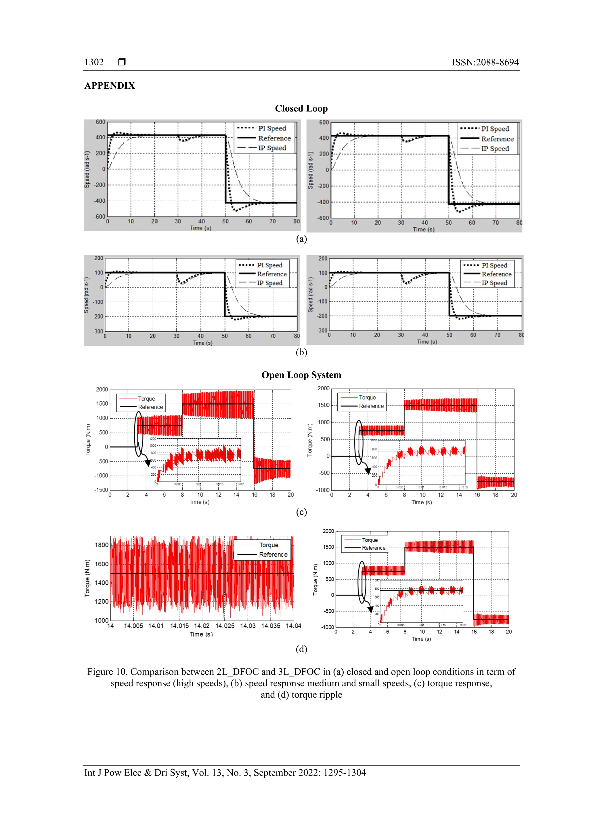
This document evaluates a new field-oriented induction machine control strategy using three-level neutral point piloted inverters compared to traditional two-level inverters for railway traction applications. The study demonstrates that the three-level inverter significantly reduces current distortion and torque ripples, enhancing efficiency and potentially lowering costs of railway traction systems. Overall, the findings indicate improved steady-state and transient performances with the new inverter strategy.
![International Journal of Power Electronics and Drive Systems (IJPEDS)
Vol. 13, No. 3, September 2022, pp. 1295~1304
ISSN: 2088-8694, DOI: 10.11591/ijpeds.v13.i3.pp1295-1304 1295
Journal homepage: http://ijpeds.iaescore.com
Assessment of field oriented induction machine control strategy
using new generation of inverters in BB36000 locomotive
Hamid Chaikhy1,2
, Mouna Es-saadi3
, Mohamed Khafallah3
1
Department of Electrical and Energy Engineering, National Engineering School of Applied Sciences, University Chouaib Doukkali,
El Jadida, Morocco
2
Laboratory of Engineering Sciences for Energy, University Chouaib Doukkali, El Jadida, Morocco
3
Laboratory of Energy and Electrical Systems, National School of Electricity and Mechanics, University Hassan II,
Casablanca, Morocco
Article Info ABSTRACT
Article history:
Received Apr 26, 2022
Revised Jun 3, 2022
Accepted Jun 20, 2022
Due to their excellent characteristics; Reaching high voltage inverters by
using lower voltage switches, reduced output current distortion, dv/dt, and
switching losses decrease, efficiency rise, multilevel inverters are an
interesting alternative to the two-level inverters especially in traction
applications. Many studies compared both topologies, but this work compare
performances of Field oriented control strategy using two levels and neutral
point piloted three levels inverter supplied by space pulse width modulation.
Based on real parameters, this work shows that this efficient multilevel
inverter reduces current distortion and torque ripples in a manner to reduces
the size and cost of all railway traction systems chosen for this work.
Keywords:
Field oriented control
Neutral point piloted inverter
Railway traction
Space pulse width modulation
This is an open access article under the CC BY-SA license.
Corresponding Author:
Hamid Chaikhy
Department of Electrical and Energy Engineering, National Engineering School of Applied Sciences
University Chouaib Doukkali
Route d’azzemour, Nationale N1, Elhaouzia BP: 116 El Jadida 24002, Marocco
Email: chaikhy.hamid@gmail.com
1. INTRODUCTION
In the United States, more than 25% of total greenhouse emissions are due to the transportation
sector 50% reduction in this ratio will give an important reduction in total greenhouse gas emissions [1]-[3].
Due to their reduced greenhouse emissions and reduced reliance on fossil fuels, electric vehicles (EVs) are
the best alternative vehicles in this critical environmental context. Even, EVs do not produce any emissions;
the generation of electricity can still produce emissions. However, compared to internal combustion engine
vehicles (ICEVs), EVs still produce 50% lower of greenhouse emissions. EVs are offering many
opportunities, but they also face many challenges, particularly concerning the battery of EVs. The
unavailability of chargers and their high cost compared to the ICEVs, the limited energy density of batteries,
slow recharging compared to the refueling of ICEVs are the major limitations to a huge expansion of that
environmentally friendly transportation mean [4]. To reduce the recharging time, many works try to increase
the Evs' battery voltage. Higher DC-link voltage enables extreme fast charging and decreases the cable size
and weight [5]-[7]. However, it needs new requirements regarding the inverter, devices or structure needs to
be improved in such a manner to withstand high voltages [8]. Because of its higher electromagnetic
interference, the use of two levels inverter can damage the electric motor. Although, its reduced conduction
losses, two levels inverter presents important switching losses. Hence, the inverter efficiency decreases [9].
Numerous industrials used higher input voltages inverters by moving to 1200 V and 1700 V IGBTs and](https://image.slidesharecdn.com/0321238-241008010800-9bc7e3b7/75/Assessment-of-field-oriented-induction-machine-control-strategy-using-new-generation-of-inverters-in-BB36000-locomotive-1-2048.jpg)
![ ISSN:2088-8694
Int J Pow Elec & Dri Syst, Vol. 13, No. 3, September 2022: 1295-1304
1296
MOSFETS [6], [7], [10], [11]. Even though high voltages switch inverters could attain high voltages, high
switching losses and high dv/dt are maintained in two levels inverter. Due to their excellent characteristics,
the multilevel inverter can be a very attractive alternative to the two levels inverter for traction applications.
Reaching high voltage inverters by using lower voltage switches, reduced output current distortion, dv/dt and
switching losses decrease, and efficiency rise are the main opportunities offered by multilevel inverters to the
new traction applications [12]-[14]. Many comparisons between two levels and multilevel inverters have
been made in the literature. Thanks to the multilevel inverter, efficiency is improved in standard driving
cycles [15], [16], costs of the two systems are compared [13], [15]. Thanks to the lower filter and battery cost
in the case of multilevel drive, the overall system is cheaper even if the cost of a multilevel inverter is softly
higher than two levels inverter. The previous studies have studied topologies. Anyway, another aspect of
multilevel traction drives that need to be investigated and compared: Performances of control strategies. This
work aims to show the performances improvement of a conventional Field oriented induction machine
control strategy in both steady-state and transient conditions by using neutral point piloted three levels
inverter NPP, instead of two levels inverter controlled by space pulse width modulation. Very used in
Moroccan railways, BB 36000 is the locomotive chosen to be improved in this work. Using real parameters,
very interesting simulations results are obtained and discussed after explaining the principle off field-oriented
control (FOC) and net primary production (NPP) inverter.
2. PRINCIPLE OF DFOC STRATEGY FOR INDUCTION MACHINE USING TWO LEVELS
INVERTER
FOC is a method of controlling a rotating field machine in such a manner to attain independent
control over the torque and the flux components of the stator current [17]. It makes it possible to control the
induction machine like the control of a separately excited DC machine, and hence it enables the use of
induction motors in applications requiring high-dynamic performance, where traditionally only DC drives
were applied. The concept of FOC applied to induction motor drives, allows us to perform fast and fully
decoupled control of torque and flux [18]. To obtain such a decoupled control, FOC algorithms need to know
the rotor flux angular position to correctly align the stator current vector. As a consequence, it is possible to
control torque and rotor flux in a DC machine control fashion, by acting on two separated components of the
stator current isd and isqin (1).
Figure 1. Orientation of the rotor field to d axis of the (d,q) reference
After applying the rotor field rotation, Figure 1, 𝜓𝑟𝑑
^
= 𝜓𝑟
^
and𝜓𝑟𝑞
^
= 0 . Induction machine (IM)
relations becomes then:
{
𝜓𝑟𝑑 =
𝑀
1+𝑝𝑇𝑟
𝑖𝑠𝑑
𝑇𝑒 = 𝑛𝑝
𝑀
𝐿𝑟
𝜓𝑟𝑖𝑠𝑞
(1)
before the determination of rotor flux, angular position is required before applying this orientation. Direct
field-oriented control (DFOC) and indirect field-oriented control (IFOC) are the two methods used to obtain
this position.
Using (2), 𝜓𝑟
^
and𝑇𝑒
^
are estimated using 𝑖𝑠𝑑and 𝑖𝑠𝑞 respectively, and are compared to 𝜓𝑟
∗
and 𝑇𝑒
∗
. As
shown in Figure 2 torque and flux are directly controlled in DFOC.](https://image.slidesharecdn.com/0321238-241008010800-9bc7e3b7/75/Assessment-of-field-oriented-induction-machine-control-strategy-using-new-generation-of-inverters-in-BB36000-locomotive-2-2048.jpg)
![Int J Pow Elec & Dri Syst ISSN:2088-8694
Assessement of field oriented induction machine control strategy using new generation…(Hamid Chaikhy)
1297
{
𝑣𝑠𝑑 = [(𝑅𝑠 + 𝑝𝜎𝔏𝑠)
(1+𝑇𝑟𝑝)
ℳ
+
ℳ
𝔏𝑟𝑝
] 𝜓𝑟𝑑 − 𝑤𝑠𝔏𝑠𝜎𝑖𝑠𝑞
𝑣𝑠𝑞 = (𝑅𝑠 + 𝑝𝜎𝔏𝑠)
𝑇𝑒
𝑝
𝑀
𝐿𝑟
𝜓𝑟𝑑
+ 𝑤𝑠𝔏𝑠𝜎𝑖𝑠𝑑 + 𝑤𝑠
ℳ
𝔏𝑟
𝜓𝑟
𝜓𝑟 =
𝑀
1+𝑝𝑇𝑟
𝑖𝑠𝑑
𝑇𝑒 = 𝑛𝑝
𝑀
𝐿𝑟
𝜓𝑟𝑖𝑠𝑞
𝜃𝑠 = ∫(𝑛𝑝Ω +
𝑀
𝑇𝑟
𝑖𝑠𝑞
∗
𝜓𝑟𝑑
∗ )𝑑𝑡
(2)
Figure 2 shows the control strategy scheme of DFOC.
Figure 2. Direct Field oriented control strategy scheme of IM using two levels inverter
To ensure decoupled control for torque and flux, compensation terms femd and femq (3) are added to
obtain a d and q axes completely independent.
{
𝑓𝑒𝑚𝑑 = 𝑤𝑠𝔏𝑠𝜎𝑖𝑠𝑞
𝑓𝑒𝑚𝑞 = 𝑤𝑠𝔏𝑠𝜎𝑖𝑠𝑑 + 𝑤𝑠
ℳ
𝔏𝑟
𝜓𝑟
(3)
In (2) shows that how position θs and voltages vsq, vsd are calculated. Using Park position θs, vsq, and vsd are
transformed and injected to the two levels inverter. A sinusoidal pulse width modulation is used to control this
inverter Figure 3. In SPWM modulation, pulses resulting from the comparison between a sinusoidal reference
signal and triangular carrier are injected to the switches, to obtain two voltage levels [19].
Figure 3. Principle of the SPWM two levels control strategy](https://image.slidesharecdn.com/0321238-241008010800-9bc7e3b7/75/Assessment-of-field-oriented-induction-machine-control-strategy-using-new-generation-of-inverters-in-BB36000-locomotive-3-2048.jpg)
![ ISSN:2088-8694
Int J Pow Elec & Dri Syst, Vol. 13, No. 3, September 2022: 1295-1304
1298
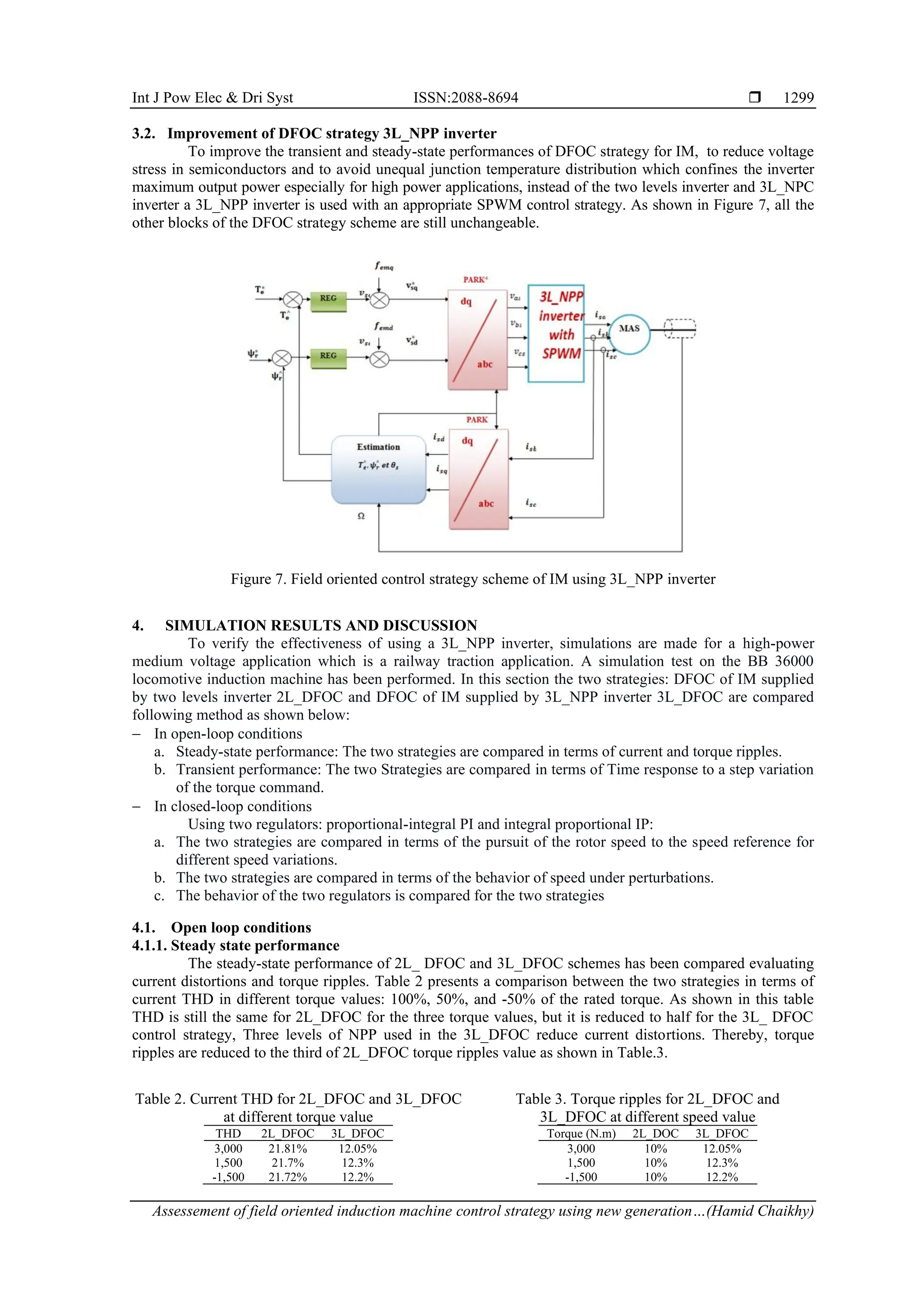
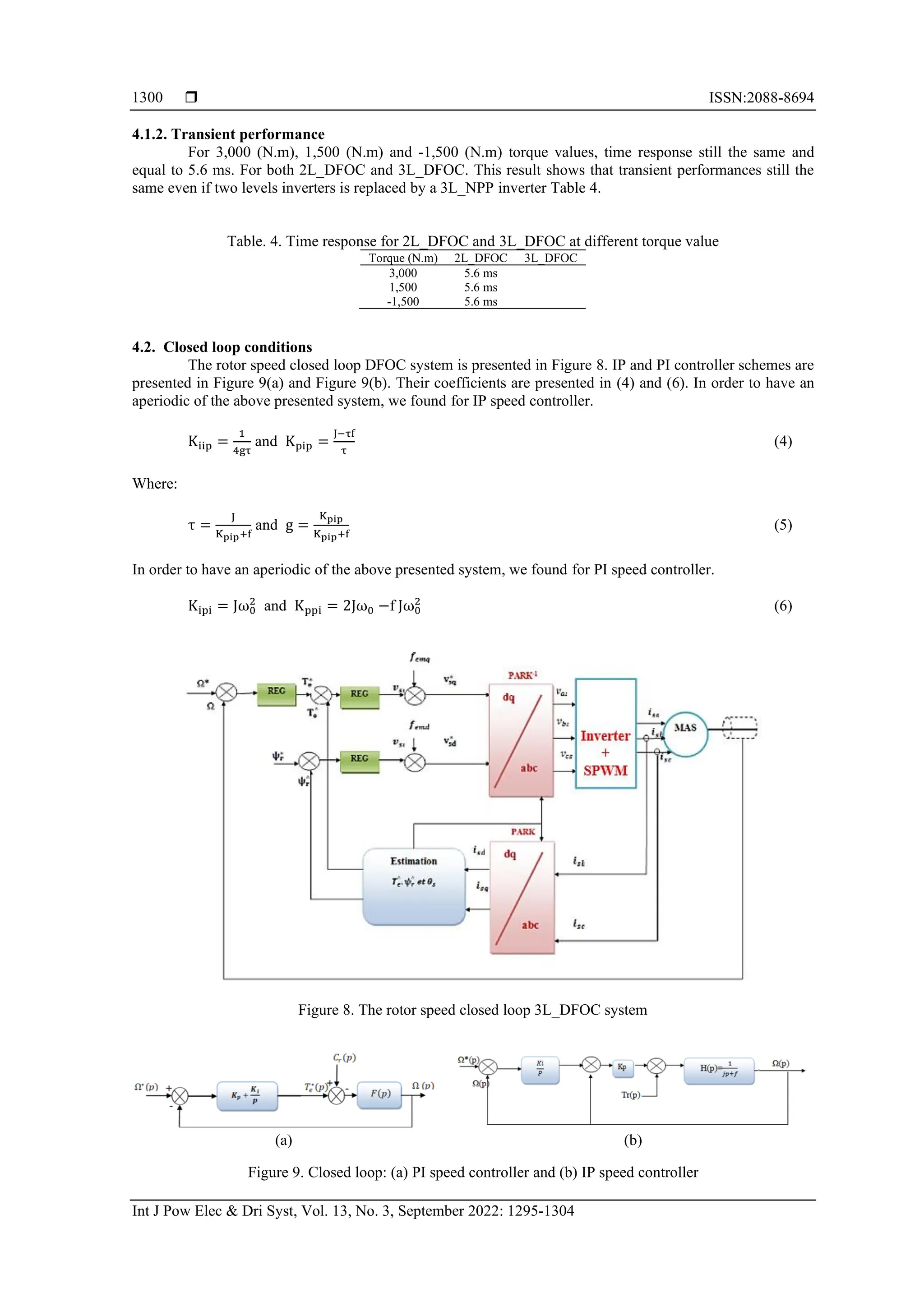
3. IMPROVEMENT OF DFOC STRATEGY FOR IM
To improve performances given by the classical structures with two voltages levels, multilevel
conversion structures constitute an interesting solution. For medium voltage high power applications such as
railway traction, the cost of semiconductor devices is increased. Multilevel structures offer a reduction of the
voltage stress that compensates for the increased number of devices. Also, by lowering the total harmonic
content, these structures offer the advantage of reducing the size of the output filter and then the cost of the
overall system. Moreover, torque ripples for motor drive applications will be reduced. Even if, NPC inverters
have a wide industrial spread mostly in medium voltage applications. They have disadvantages; like unequal
switches losses distribution. To solve this problem, three levels NPP (3L_NPP) inverter is the multilevel
inverter chosen to be used to replace the two levels inverter [20]-[23].
3.1. Principle of the 3L_NPP inverter
As shown in Figure 4, two capacitors that have the same capacitance are used to divide equally the
voltage and obtain two voltage levels. Each leg of the 3L-NPP inverter contains two head-to-tail connected
and clamped IGBTs and four other vertical IGBTs, each IGBT has an antiparallel connected diode. To obtain
the three voltage levels, switches are following switching states as shown in Table 1. Figure 5 shows the two
carriers sinusoidal pulse width modulation (SPWM) control strategy used for one leg of the NPP
inverter [24], [25].The following Figure6 shows the output voltages of the inverter simulated in
MATLAB/Simulink where the three voltage levels are observed.
Figure 4. Structure of a 3L_NPP inverter brush Figure 5. SPWM of the 3L_NPP inverter
Table 1. Basic switching of the three levels NPP inverter
Voltage Va T2+ T1+ TC+ T2- T1- TC-
Vdc/2 1 1 1 0 0 0
0 0 0 1 0 0 1
-Vdc/2 0 0 0 1 1 1
Figure 6. Output voltages of the five levels NPC inverter](https://image.slidesharecdn.com/0321238-241008010800-9bc7e3b7/75/Assessment-of-field-oriented-induction-machine-control-strategy-using-new-generation-of-inverters-in-BB36000-locomotive-4-2048.jpg)
![Int J Pow Elec & Dri Syst ISSN:2088-8694
Assessement of field oriented induction machine control strategy using new generation…(Hamid Chaikhy)
1303
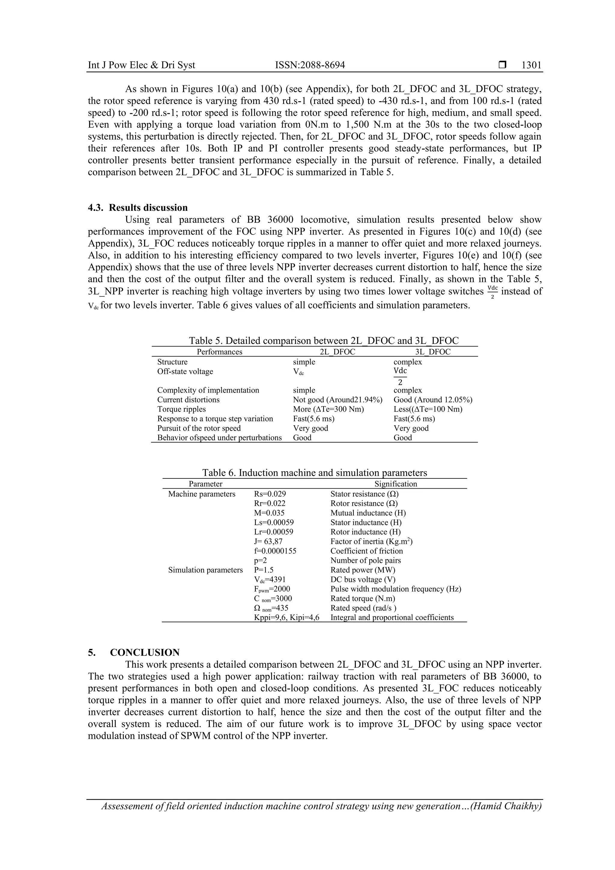
(e)
(f)
Figure 10. Comparison between 2L_DFOC and 3L_DFOC in (e) current distortions and (f) THD current
(continue)
REFERENCES
[1] M. Muratori et al., “The rise of electric vehicles-2020 status and future expectations,” IOP Science, vol. 3, no. 2, Jan. 2021, doi:
10.1088/2516-1083/abe0ad.
[2] M. Broy, “Challenges in automotive software engineering,” in ICSE’06:Proceedings of the 28th international conference on
Software engineering, May 2006 pp. 33-42, doi: 10.1145/1134285.1134292.
[3] J. Cao, X. Chen, R. Qiu, and S. hou, “Electric vehicle industry sustainable development with a stakeholder engagement system,”
Technoloy in Society, vol. 67, Nov. 2021, doi: 10.1016/j.techsoc.2021.101771.
[4] A. Tomaszewska et al., “Lithium ion battery fast charging: A review,” eTransportation, vol. 1, Aug. 2019, doi:
10.1016/j.etran.2019.100011.
[5] M. Mosaraf , A. Hossain , A. Ullah, M. Shahad , S. Shahnewaz, M. Shafiul, T. Jamal, H. Ahmed, “Integration of Large-Scale
Electric Vehicles into Utility Grid: An Efficient Approach for Impact Analysis and Power Quality Assessment,” Sustainability,
vol. 13, no. 19, pp. 1-18, Oct. 2021, doi: 10.3390/su131910943.
[6] O. Heidrich, G.nHill, M. Neaimeh, Y. Huebner, P. Blythe, R. Dawson, “How do cities support electric vehicles and what
difference does it make?,” Technological Forecasting and Social Change, vol. 123, pp. 17-23, Oct. 2017, doi:
10.1016/j.techfore.2017.05.026.
[7] C. Jung, “Power Up with 800-V Systems: The benefits of upgrading voltage power for battery-electric passenger vehicles,” in
IEEE Electrification Magazine, vol. 5, no. 1, pp. 53-58, Mar. 2017, doi: 10.1109/MELE.2016.2644560.
[8] D. Ronanki, A. Kelkar, and S. S. Williamson, “Extreme fast charging technology-Prospects to enhance sustainable electric
transportation,”Energies, vol. 12, no. 19, p. 3721, Sep. 2019, doi: 10.3390/en12193721.
[9] N. Soualhi, A. Makouf, N. Nait-Said, and S. Hamada, “Comparison between a Two-Level and Three-Level Inverter fed Induction
Motor including Losses and Efficiency,”in 4th International Conference on Advanced Systems and Emergent Technologies
(IC_ASET), 2020, pp. 89-94, doi: 10.1109/IC_ASET49463.2020.9318310.
[10] H. Tu, H. Feng, S. Srdic, and S. Lukic, “Extreme Fast Charging of Electric Vehicles: A Technology Overview,” in IEEE
Transactions on Transportation Electrification, vol. 5, no. 4, pp. 861-878, Dec. 2019, doi: 10.1109/TTE.2019.2958709.
[11] K. Zhang, J. Yang, C. Liu, J. Wang, and D. Yao, “Dynamic Characteristics of a Traction Drive System in High-Speed Train
Based on Electromechanical Coupling Modeling under Variable Conditions,” Energies, vol. 15, Feb. 2022, doi:
10.3390/en15031202.
[12] A. Choudhury, P. Pillay and S. S. Williamson, "Comparative Analysis Between Two-Level and Three-Level DC/AC Electric
Vehicle Traction Inverters Using a Novel DC-Link Voltage Balancing Algorithm," in IEEE Journal of Emerging and Selected
Topics in Power Electronics, vol. 2, no. 3, pp. 529-540, Sep. 2014, doi: 10.1109/JESTPE.2014.2310140.
[13] R. Teichmann and S. Bernet, "A comparison of three-level converters versus two-level converters for low-voltage drives, traction,
and utility applications," in IEEE Transactions on Industry Applications, vol. 41, no. 3, pp. 855-865, May-June 2005, doi:
10.1109/TIA.2005.847285.
[14] L. Dorn-Gomba, J. Ramoul, J. Reimers, and A. Emadi, "Power Electronic Converters in Electric Aircraft: Current Status,
Challenges, and Emerging Technologies," in IEEE Transactions on Transportation Electrification, vol. 6, no. 4, pp. 1648-1664,
Dec. 2020, doi: 10.1109/TTE.2020.3006045.
[15] F. Chang, O. Ilina, M. Lienkamp, and L. Voss, "Improving the Overall Efficiency of Automotive Inverters Using a Multilevel
Converter Composed of Low Voltage Si mosfets," in IEEE Transactions on Power Electronics, vol. 34, no. 4, pp. 3586-3602,
April 2019, doi: 10.1109/TPEL.2018.2854756.](https://image.slidesharecdn.com/0321238-241008010800-9bc7e3b7/75/Assessment-of-field-oriented-induction-machine-control-strategy-using-new-generation-of-inverters-in-BB36000-locomotive-9-2048.jpg)
![ ISSN:2088-8694
Int J Pow Elec & Dri Syst, Vol. 13, No. 3, September 2022: 1295-1304
1304
[16] M. Quraan, P. Tricoli, S. D’Arco and L. Piegari, "Efficiency Assessment of Modular Multilevel Converters for Battery Electric
Vehicles," in IEEE Transactions on Power Electronics, vol. 32, no. 3, pp. 2041-2051, March 2017, doi:
10.1109/TPEL.2016.2557579.
[17] K. Hasse, “On the dynamics of speed control of a static AC drive with squirrel cage induction machine,” Ph.D. dissertation, Tech.
Hochschule Darmstradt, Germany, 1969.
[18] R. Garg, P. Mahajan, N. Gupta, H.Saroa, “A comparative study between field oriented control and direct torque control of AC
traction motor,” in International Conference on Recent Advances and Innovations in Engineering, May. 2014, doi:
10.1109/ICRAIE.2014.6909201.
[19] H. Chaikhy, M.Khafallah, A. Saad, M. Es-Saadi, and K. Chikh, “Evaluation des performances des commandes vectorielles de la
machine à induction,”Revue de génie industriel, vol. 6, pp. 23-32, Jan. 2011.
[20] V. Guennegues, B. Gollentz, F. Meibody-Tabar, S. Rael, and L. Leclere, "A converter topology for high speed motor drive
applications," 2009 13th European Conference on Power Electronics and Applications, 2009, pp. 1-8.
[21] J. I. Leon, S. Vazquez and L. G. Franquelo, "Multilevel converters: Control and modulation techniques for their operation and
industrial applications", Proc. IEEE, vol. 105, no. 11, pp. 2066-2081, Nov. 2017, doi: 10.1109/JPROC.2017.2726583.
[22] V. Gennegues, “Contribution à l'étude des convertisseurs multiniveaux destinés aux applications moteurs rapides,” M.S. thesis,
Univ. Lorraine, Lorraine, Suisse, 2009.
[23] V. Guennegues, B. Gollentz, L. Leclere, F. Meibody-Tabar, and S. Raël, “Selective harmonic elimination PWM applied to H-
bridge topology in high speed applications”, in International Conference on Power Engineering, Energy and Electrical Drives,
May. 2009, doi: 10.1109/POWERENG.2009.4915189.
[24] W. Brumsickle, D. Divan, and T. Lipo, “Reduced switching stress in high-voltage IGBT inverters via a three-level structure," in
APEC 98 Thirteenth Annual Applied Power Electronics Conference and Exposition, Aug. 1998, doi: 10.1109/APEC.1998.653944.
[25] H. Akagi, “Multilevel Converters: Fundamental Circuits and Systems ,” in Proceedings of the IEEE, vol. 105, no. 11, Nov. 2017,
doi: 10.1109/JPROC.2017.2682105.
BIOGRAPHIES OF AUTHORS
Hamid Chaikhy was born in Morocco in 1975. He received M. Sc. Degree
from University of Ibn Zohr, Agadir in 2005. In 2013, he received Doctorate degree from
the Department of Electrical Engineering at the National School of Electricity and
Mechanics (ENSEM), Hassan II University, Casablanca. His current research interests are
the areas of field-oriented control and motor drives. He can be contacted at email:
chaikhy.hamid@gmail.com.
Mouna Es-Saadi was born in Morocco in 1985. In 2018, she received,
Doctorate degree from the Department of Electrical Engineering at the National School of
Electricity and Mechanics (ENSEM), Hassan II University, Casablanca. In 2009, she
received her diploma at Electrical engineering from the national school of applied sciences,
Cadi Ayyad university, Marrakech. His current research interests are the areas of energy
efficiency, applications of power electronics and motor drives. She can be contacted at
email: mounaessaadi2@gmail.com.
Mohamed Khafallah was born in Morocco in 1964. He received B.Sc., M.Sc.
and Doctorate degrees from Hassan II University of Casablanca, in 1989, 1991 and 1995
respectively, all in Electrical Engineering. In 1995 he joined the National High School of
Electricity and Mechanics (ENSEM), Hassan II University of Casablanca, Morocco, where
he is currently professor tutor in the Department Electrical Engineering and chief of
Laboratory Energy and Electricals Systems (LESE). His main research interests the
application of power electronics converters, motor drives and renewable energy. He has
published a lot of research papers in international journals, conference proceedings as well
as chapters of books. He can be contacted at email: m.khafallah@ensem.ac.ma.](https://image.slidesharecdn.com/0321238-241008010800-9bc7e3b7/75/Assessment-of-field-oriented-induction-machine-control-strategy-using-new-generation-of-inverters-in-BB36000-locomotive-10-2048.jpg)


![[9_CV] FCS-Model Predictive Control of Induction Motors feed by MultilLevel C...](https://cdn.slidesharecdn.com/ss_thumbnails/9cvfcs-modelpredictivecontrolofinductionmotorsfeedbymultillevelcasadedh-bridgeinverter-190418083950-thumbnail.jpg?width=640&height=640&fit=bounds)