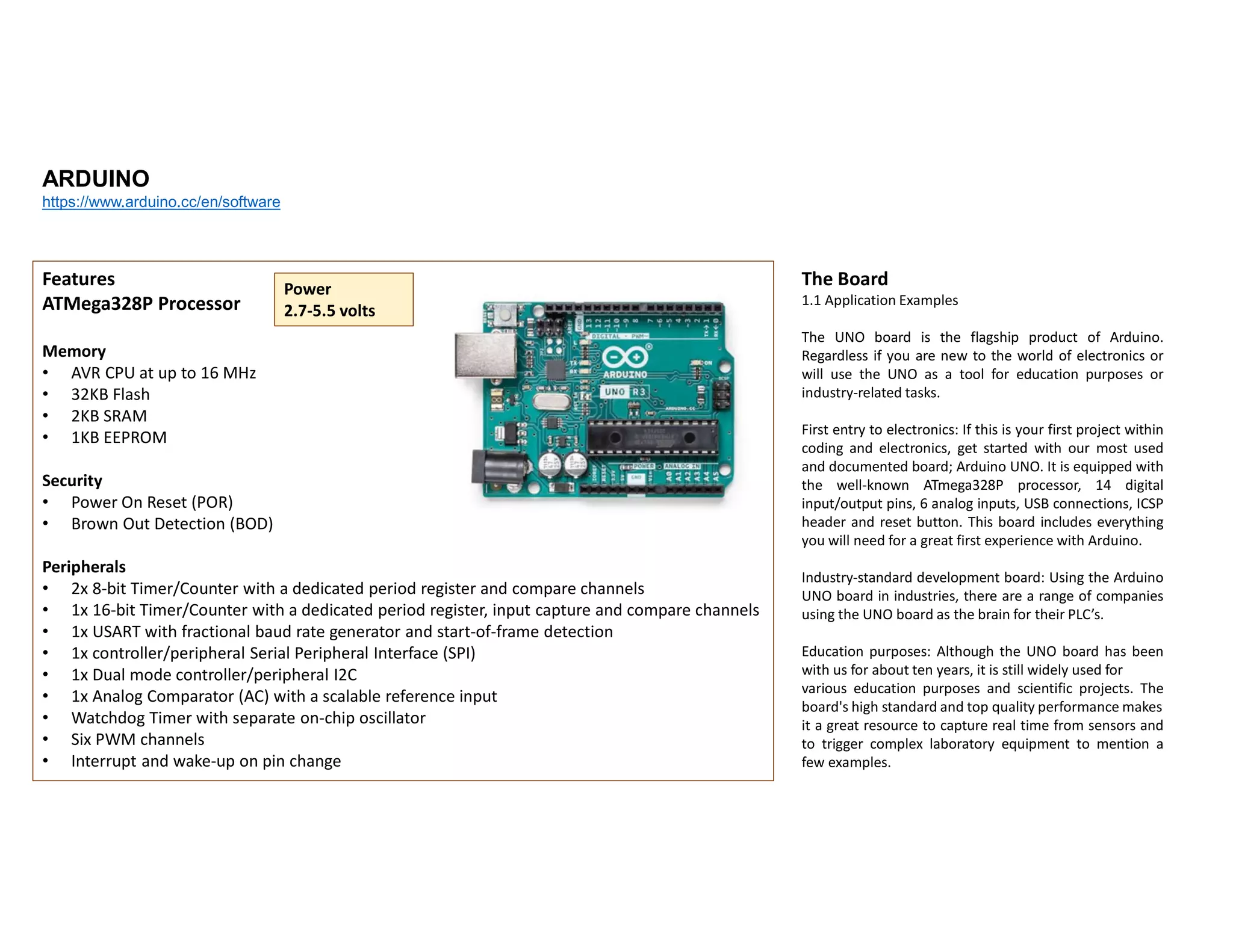
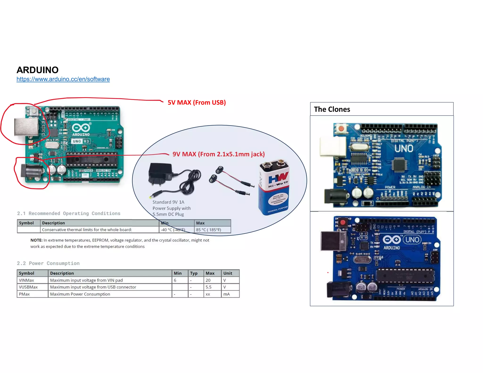
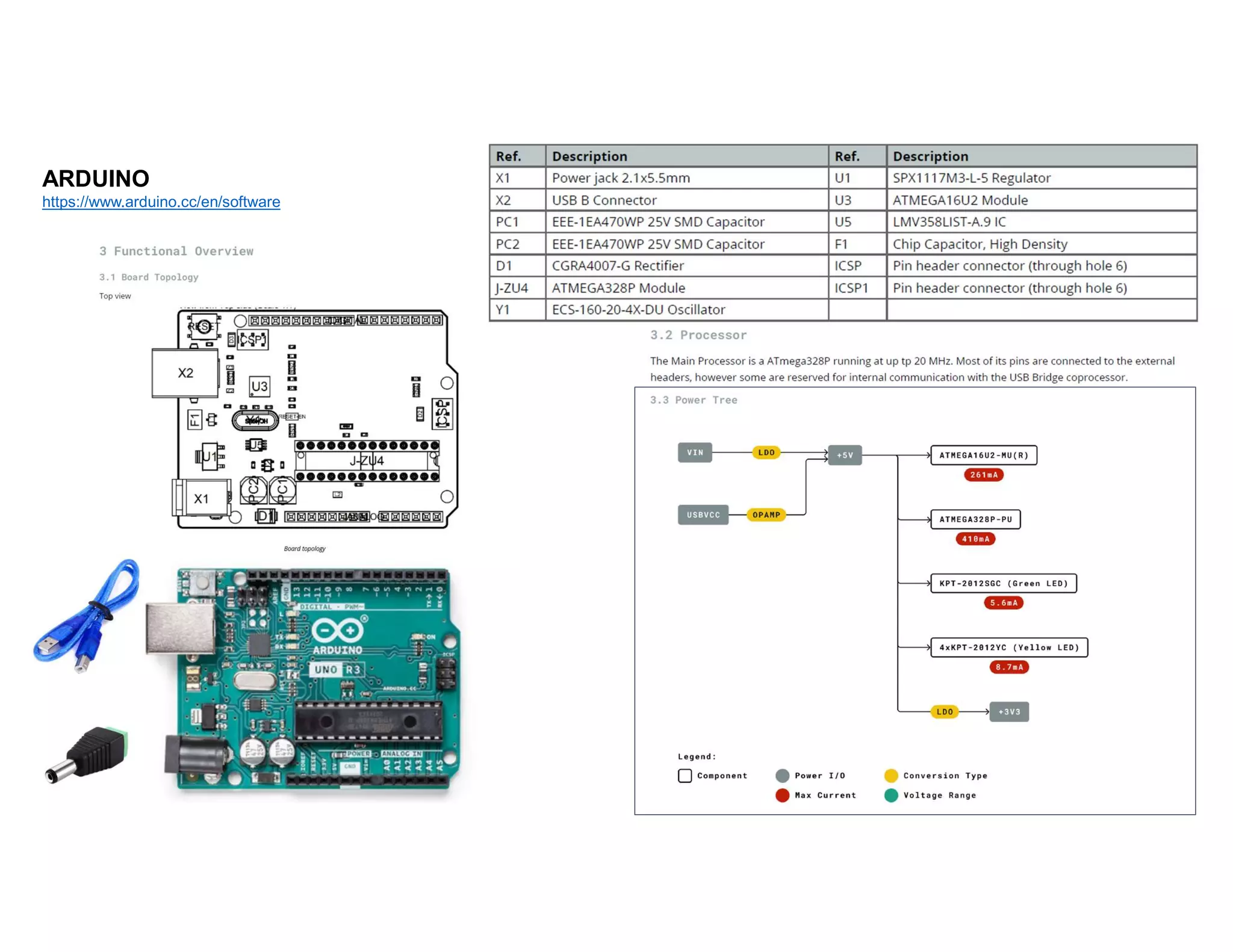
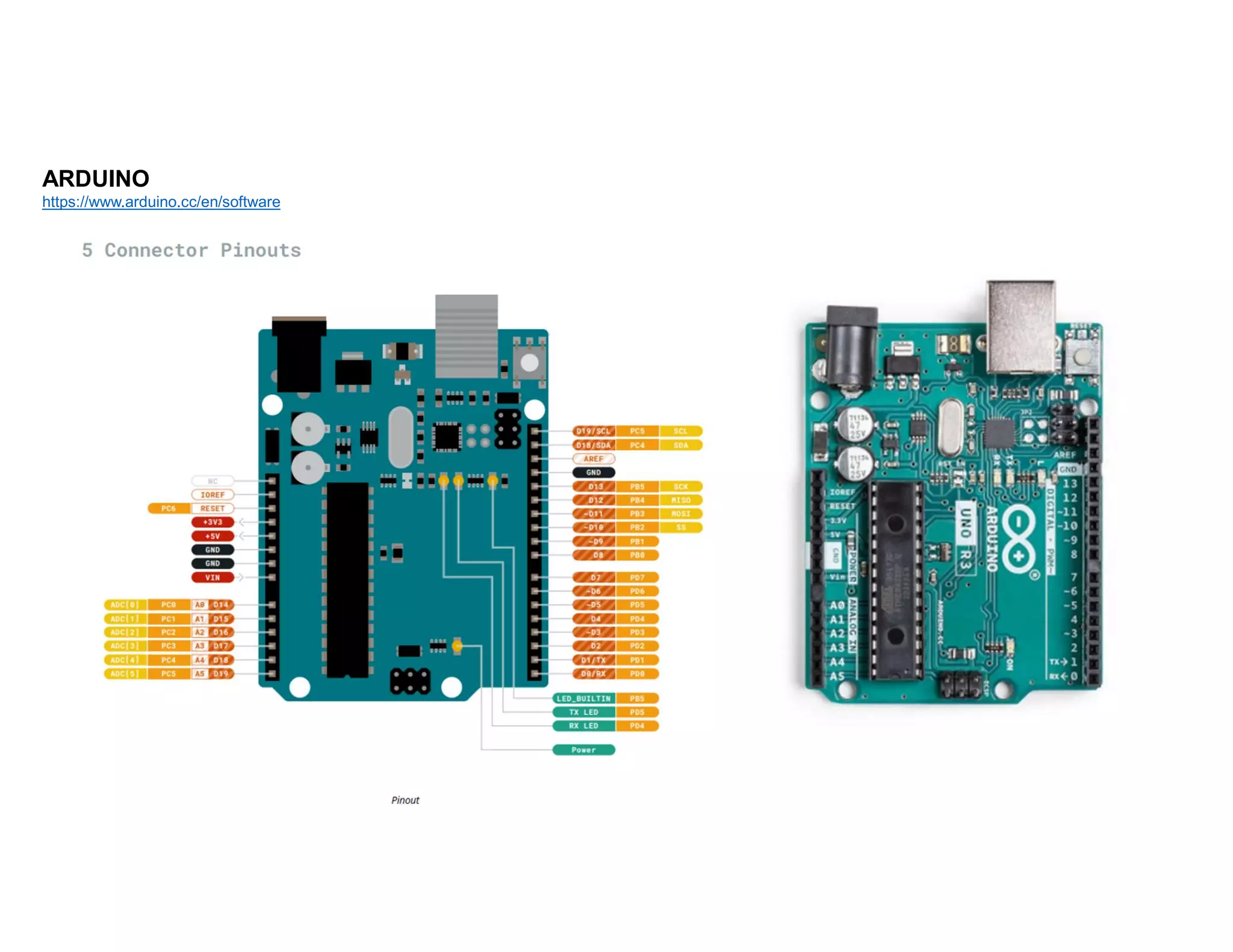
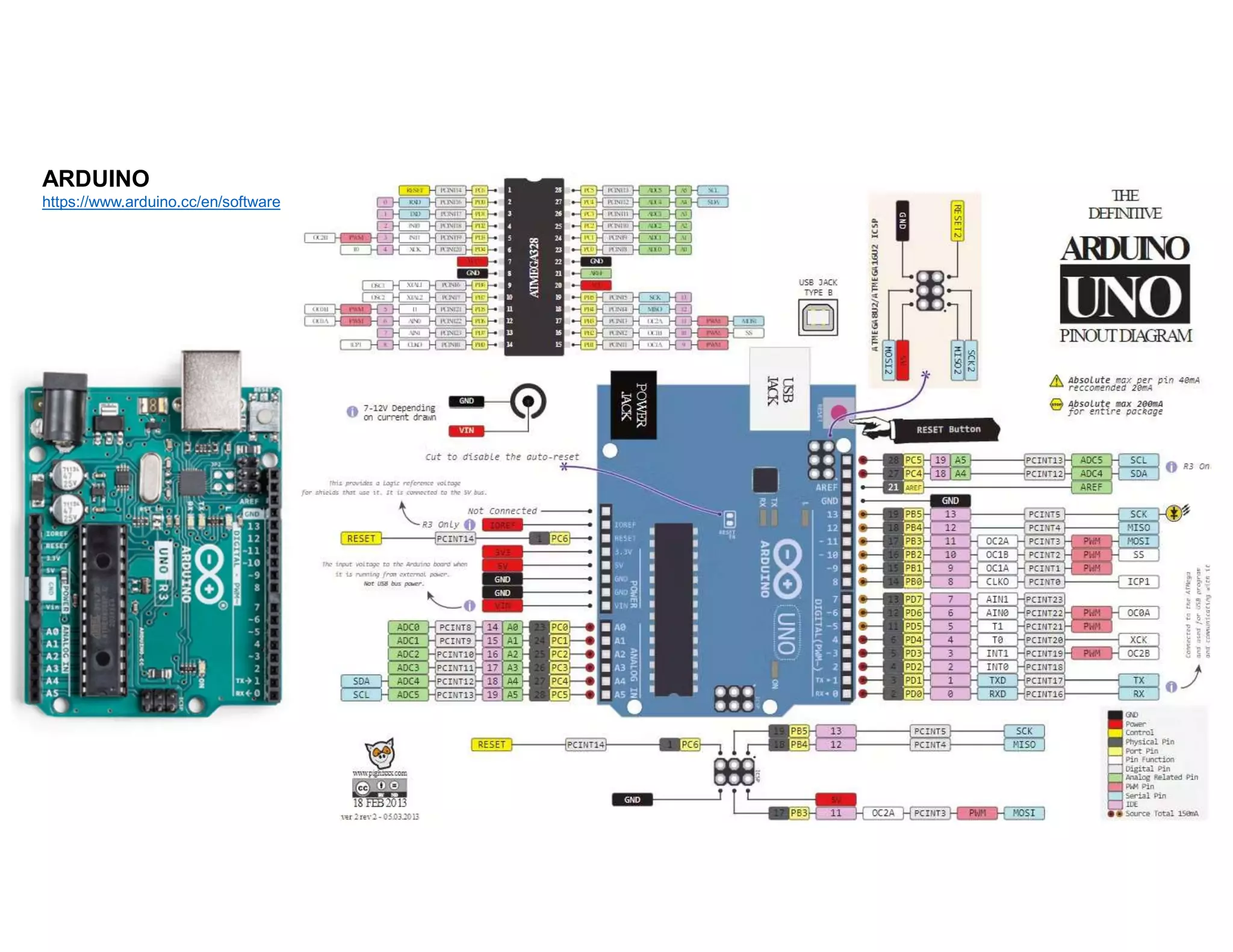
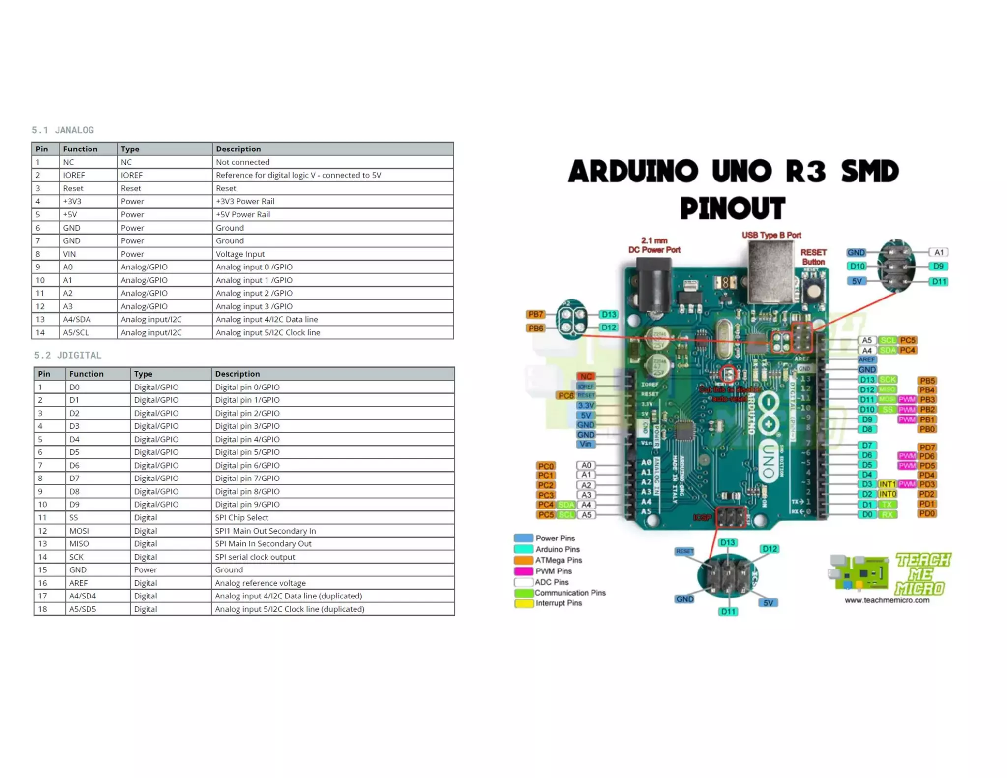
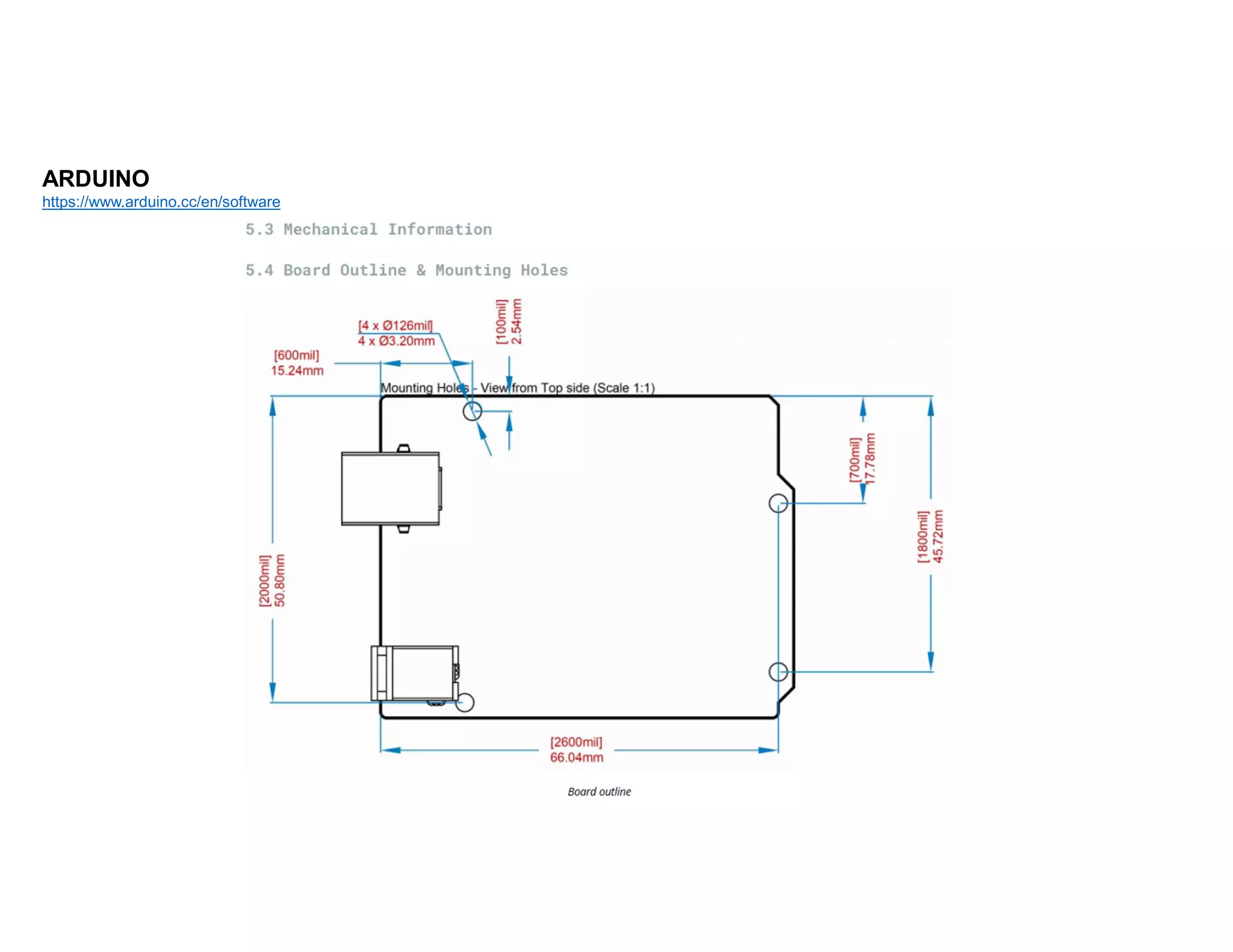
ARDUINO
https://www.arduino.cc/
Register and Sign in
ARDUINO
https://www.arduino.cc/en/software
Features
ATMega328P Processor
Memory
• AVR CPU at up to 16 MHz
• 32KB Flash
• 2KB SRAM
• 1KB EEPROM
Security
• Power On Reset (POR)
• Brown Out Detection (BOD)
Peripherals
• 2x 8-bit Timer/Counter with a dedicated period register and compare channels
• 1x 16-bit Timer/Counter with a dedicated period register, input capture and compare channels
• 1x USART with fractional baud rate generator and start-of-frame detection
• 1x controller/peripheral Serial Peripheral Interface (SPI)
• 1x Dual mode controller/peripheral I2C
• 1x Analog Comparator (AC) with a scalable reference input
• Watchdog Timer with separate on-chip oscillator
• Six PWM channels
• Interrupt and wake-up on pin change
Power
2.7-5.5 volts
The Board
1.1 Application Examples
The UNO board is the flagship product of Arduino.
Regardless if you are new to the world of electronics or
will use the UNO as a tool for education purposes or
industry-related tasks.
First entry to electronics: If this is your first project within
coding and electronics, get started with our most used
and documented board; Arduino UNO. It is equipped with
the well-known ATmega328P processor, 14 digital
input/output pins, 6 analog inputs, USB connections, ICSP
header and reset button. This board includes everything
you will need for a great first experience with Arduino.
Industry-standard development board: Using the Arduino
UNO board in industries, there are a range of companies
using the UNO board as the brain for their PLC’s.
Education purposes: Although the UNO board has been
with us for about ten years, it is still widely used for
various education purposes and scientific projects. The
board's high standard and top quality performance makes
it a great resource to capture real time from sensors and
to trigger complex laboratory equipment to mention a
few examples.
ARDUINO
https://www.arduino.cc/en/software
The Clones
9V MAX (From 2.1x5.1mm jack)
5V MAX (From USB)
Standard 9V 1A
Power Supply with
5.5mm DC Plug
ARDUINO
https://www.arduino.cc/en/software
ARDUINO
https://www.arduino.cc/en/software
ARDUINO
https://www.arduino.cc/en/software
ARDUINO
https://www.arduino.cc/en/software
ARDUINO
https://www.arduino.cc/en/software
ARDUINO IDE
Buzzers can be categorized into two different types – active buzzers and passive buzzers. An active buzzer has a built-in oscillator so
it can produce sound with only a DC power supply. A passive buzzer does not have a built-in oscillator, so it needs an AC audio signal
to produce sound.
ACTIVE BUZZERS
Active buzzers are the simplest to use. They are typically available in voltages from 1.5V to 24V. All you need to do is apply a DC
voltage to the pins and it will make a sound.
Active buzzers have polarity. The polarity is the same as an LED and a capacitor – the longer pin goes to positive. One downside of
active buzzers is that the frequency of the sound is fixed and cannot be adjusted.
INSIDE AN ACTIVE BUZZER
Let’s cut into an active buzzer to see what lurks beneath that neat plastic exterior:
The gold disc on the right is a piezoelectric disk that vibrates when a voltage is applied. The three metal fingers on the PCB make
contact with the disc, and a little transistor amplifier is on the printed circuit board.
PASSIVE BUZZERS
Passive buzzers need an AC signal to produce sound. the downside to this is that they will need more complex circuitry to control
them, like an oscillating 555 timer or a programmable microcontroller like the Arduino.
Passive buzzers have the advantage that they can vary the pitch or tone of the sound. Passive buzzers can be programmed to emit a
wide range of frequencies or musical notes.
INSIDE A PASSIVE BUZZER
Now let’s cut open a passive buzzer:
In a passive buzzer, we find an anatomy similar to a loudspeaker. There is a circular magnet surrounding an inner wire coil, with a disk
that vibrates from the magnetic force generated by the electromagnetic coil.
COMPONENTS - BUZZERS
https://www.circuitbasics.com/how-to-use-active-and-passive-buzzers-on-the-arduino/
//Arduino Code for Active Buzzer
int buzzerPin = 8;
int buttonPin = 7;
void setup() {
pinMode(buzzerPin, OUTPUT);
pinMode(buttonPin, INPUT_PULLUP);
}
void loop() {
int buttonState = digitalRead(buttonPin);
if (buttonState == LOW) {
digitalWrite(buzzerPin, HIGH);
}
if (buttonState == HIGH) {
digitalWrite(buzzerPin, LOW);
}
}
COMPONENTS - BUZZERS
https://www.circuitbasics.com/how-to-use-active-and-passive-buzzers-on-the-arduino/
//Code for Passive Buzzer
int buzzerPin = 8;
void setup() {
pinMode(buzzerPin, OUTPUT);
tone(buzzerPin, 1000, 2000);
}
void loop() {
tone(buzzerPin, 440); // A4
delay(1000);
tone(buzzerPin, 494); // B4
delay(1000);
tone(buzzerPin, 523); // C4
delay(1000);
tone(buzzerPin, 587); // D4
delay(1000);
tone(buzzerPin, 659); // E4
delay(1000);
tone(buzzerPin, 698); // F4
delay(1000);
tone(buzzerPin, 784); // G4
delay(1000);
noTone(buzzerPin);
delay(1000);
}
You can recognize the positive pin by looking at the top side of the
buzzer, you will a point marked "+", the pin on this side is the
positive pin.
Reference Link
Arduino IDE (Desktop)
https://www.arduino.cc/en/Main/Software
Arduino IDE (Cloud)
https://create.arduino.cc/editor
Cloud IDE Getting Started
https://create.arduino.cc/projecthub/Arduino_Genuino/getting-started-with-arduinoweb-editor-4b3e4a
Arduino Pro Website
https://www.arduino.cc/pro
Project Hub
https://create.arduino.cc/projecthub?by=part&part_id=11332&sort=trending
Library Reference
https://www.arduino.cc/reference/en/
Online Store
https://store.arduino.cc/

Arduino.pdf

  • 2.
  • 3.
  • 4.
    Features ATMega328P Processor Memory • AVRCPU at up to 16 MHz • 32KB Flash • 2KB SRAM • 1KB EEPROM Security • Power On Reset (POR) • Brown Out Detection (BOD) Peripherals • 2x 8-bit Timer/Counter with a dedicated period register and compare channels • 1x 16-bit Timer/Counter with a dedicated period register, input capture and compare channels • 1x USART with fractional baud rate generator and start-of-frame detection • 1x controller/peripheral Serial Peripheral Interface (SPI) • 1x Dual mode controller/peripheral I2C • 1x Analog Comparator (AC) with a scalable reference input • Watchdog Timer with separate on-chip oscillator • Six PWM channels • Interrupt and wake-up on pin change Power 2.7-5.5 volts The Board 1.1 Application Examples The UNO board is the flagship product of Arduino. Regardless if you are new to the world of electronics or will use the UNO as a tool for education purposes or industry-related tasks. First entry to electronics: If this is your first project within coding and electronics, get started with our most used and documented board; Arduino UNO. It is equipped with the well-known ATmega328P processor, 14 digital input/output pins, 6 analog inputs, USB connections, ICSP header and reset button. This board includes everything you will need for a great first experience with Arduino. Industry-standard development board: Using the Arduino UNO board in industries, there are a range of companies using the UNO board as the brain for their PLC’s. Education purposes: Although the UNO board has been with us for about ten years, it is still widely used for various education purposes and scientific projects. The board's high standard and top quality performance makes it a great resource to capture real time from sensors and to trigger complex laboratory equipment to mention a few examples. ARDUINO https://www.arduino.cc/en/software
  • 5.
    The Clones 9V MAX(From 2.1x5.1mm jack) 5V MAX (From USB) Standard 9V 1A Power Supply with 5.5mm DC Plug ARDUINO https://www.arduino.cc/en/software
  • 6.
  • 7.
  • 8.
  • 10.
  • 11.
  • 12.
    Buzzers can becategorized into two different types – active buzzers and passive buzzers. An active buzzer has a built-in oscillator so it can produce sound with only a DC power supply. A passive buzzer does not have a built-in oscillator, so it needs an AC audio signal to produce sound. ACTIVE BUZZERS Active buzzers are the simplest to use. They are typically available in voltages from 1.5V to 24V. All you need to do is apply a DC voltage to the pins and it will make a sound. Active buzzers have polarity. The polarity is the same as an LED and a capacitor – the longer pin goes to positive. One downside of active buzzers is that the frequency of the sound is fixed and cannot be adjusted. INSIDE AN ACTIVE BUZZER Let’s cut into an active buzzer to see what lurks beneath that neat plastic exterior: The gold disc on the right is a piezoelectric disk that vibrates when a voltage is applied. The three metal fingers on the PCB make contact with the disc, and a little transistor amplifier is on the printed circuit board. PASSIVE BUZZERS Passive buzzers need an AC signal to produce sound. the downside to this is that they will need more complex circuitry to control them, like an oscillating 555 timer or a programmable microcontroller like the Arduino. Passive buzzers have the advantage that they can vary the pitch or tone of the sound. Passive buzzers can be programmed to emit a wide range of frequencies or musical notes. INSIDE A PASSIVE BUZZER Now let’s cut open a passive buzzer: In a passive buzzer, we find an anatomy similar to a loudspeaker. There is a circular magnet surrounding an inner wire coil, with a disk that vibrates from the magnetic force generated by the electromagnetic coil. COMPONENTS - BUZZERS
  • 13.
    COMPONENTS - BUZZERS https://www.circuitbasics.com/how-to-use-active-and-passive-buzzers-on-the-arduino/ //ArduinoCode for Active Buzzer int buzzerPin = 8; int buttonPin = 7; void setup() { pinMode(buzzerPin, OUTPUT); pinMode(buttonPin, INPUT_PULLUP); } void loop() { int buttonState = digitalRead(buttonPin); if (buttonState == LOW) { digitalWrite(buzzerPin, HIGH); } if (buttonState == HIGH) { digitalWrite(buzzerPin, LOW); } }
  • 14.
    COMPONENTS - BUZZERS https://www.circuitbasics.com/how-to-use-active-and-passive-buzzers-on-the-arduino/ //Codefor Passive Buzzer int buzzerPin = 8; void setup() { pinMode(buzzerPin, OUTPUT); tone(buzzerPin, 1000, 2000); } void loop() { tone(buzzerPin, 440); // A4 delay(1000); tone(buzzerPin, 494); // B4 delay(1000); tone(buzzerPin, 523); // C4 delay(1000); tone(buzzerPin, 587); // D4 delay(1000); tone(buzzerPin, 659); // E4 delay(1000); tone(buzzerPin, 698); // F4 delay(1000); tone(buzzerPin, 784); // G4 delay(1000); noTone(buzzerPin); delay(1000); } You can recognize the positive pin by looking at the top side of the buzzer, you will a point marked "+", the pin on this side is the positive pin.
  • 15.
    Reference Link Arduino IDE(Desktop) https://www.arduino.cc/en/Main/Software Arduino IDE (Cloud) https://create.arduino.cc/editor Cloud IDE Getting Started https://create.arduino.cc/projecthub/Arduino_Genuino/getting-started-with-arduinoweb-editor-4b3e4a Arduino Pro Website https://www.arduino.cc/pro Project Hub https://create.arduino.cc/projecthub?by=part&part_id=11332&sort=trending Library Reference https://www.arduino.cc/reference/en/ Online Store https://store.arduino.cc/