Download to read offline
![Meha Sharma, rewa Sharma / International Journal of Engineering Research and Applications
(IJERA) ISSN: 2248-9622 www.ijera.com
Vol. 3, Issue 2, March -April 2013, pp.276-282
Data version : ADVANCED,v1.0,05-28-03 [1]. R. MLEWSKY, ”Five Years of Monitoring
Power the Impulse Test of Power Transformer
summary : I(mA) P(mW) with Digital Recorders and Transfer
--------------------------------------------------------------- Function Method”, pp.1-6,CIGRE 1992
---- .session 12-20.
Total estimated power consumption [2]. W. Wang , Y.M.Li , Y.Qui “ Application
: 204 of Wavelet Analysis to Detection of
Vccint 1.50V : 100 150 Transformer Winding Deformation,
Vccaux 2.50V : 20 50 10th ISH’ 97, pp 131-134 Montreal
Vcco25 2.50V : 2 4 Qubec Canada 1997. Peter Hoffman AND
Thermal summary: Surya Santoso, “ Power Quality
--------------------------------------------------------------- Assessment via Wavelet Transform
---- Analysis”, IEEE Transaction on Power
Estimated junction temperature : 25C Delivery Vol,.11,No 2 April 1996.
Ambient temp : 25C [4]. Daubechies, I. (1990) “ The wavelet
Case temp : 25C transform, time/frequency location and
signal analysis. IEEE Transactions on
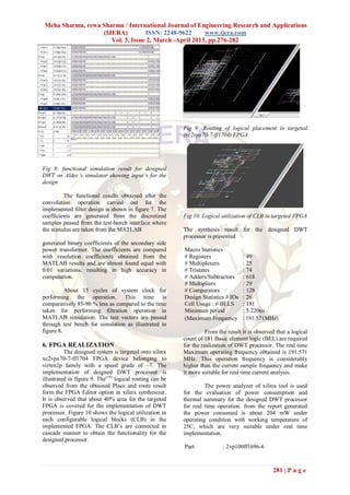
The Register transfer logic (RTL) implementation Information Theory”, 36, 961-1005.
for the designed processor is shown in figure 11. [5]. S.Masud "VLSI system for discrete wavelet
transforms", PhD Thesis, Dept. of
electrical engineering, The Queen‟s
University of Belfast, 1999.
[6]. Rioul, O. and M. Vetterli (1991) “
Wavelets and signal processing. IEEE
Signal Processing Magazine”, 14-38.
[7]. Vetterli, M. and J. Kovacevic (1995)
“ Wavelets and Subband Coding”. Prentice
Hall, Englewood Cliffs, NJ, U.S.A.
[8]. HDL Designer Series User Manual,
Software Version 2003.1,9 April 2003,
Mentor Graphics Corporation 1996-2003.
[9]. Modelsim 5.6 SE Performance Guidelines,
Model Technology February 2002, User‟s
Fig 11. RTL implemented for the designed DWT Manual, Version 5.6e, Mentor Graphics
processor. Corporation 1996-2002. “XC4000E and
XC4000X Series Field Programmable Gate
7. CONCLUSION Arrays”, Xilinx 1999.
FPGA implementation for DWT processor
for the analysis of power transformer faults is
realized. The implementation of DWT processor on
FPGA results in high speed operation of automated
power quality analyzer by replacing the existing
filter bank architecture (or) DSP based architecture
resulting in more reliable operations for power
quality analysis. The implementation results
obtained from xilinx synthesizer shows a very low
resource utilization with high speed real time
operating frequency and low power consumption
,with ambient temperature condition which are most
suitable for real time installation in power quality
analysis. The developed FPGA design could be
merged with advanced learning standards for the
total automation of fast and reliable power
transformer protections in electrical power system.
This facility leads to the concept of
reconfigurability, which is advantageous and not
high resource consuming under remote applications.
REFERENCES
282 | P a g e](https://image.slidesharecdn.com/ao32276282-130322063637-phpapp02/85/Ao32276282-7-320.jpg)

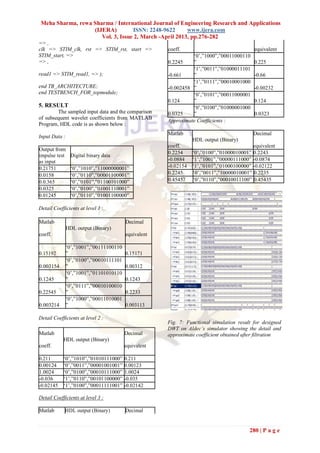
This document summarizes a study comparing the results of Discrete Wavelet Transformation (DWT) analysis using Matlab and VHDL for power systems applications. DWT is proposed to detect minor faults in power transformer windings due to its time-frequency localization properties. The authors implement a DWT architecture in VHDL and compare the wavelet coefficients obtained to theoretical results from Matlab. They find the VHDL results meet the accuracy of the Matlab estimates. The digital implementation of DWT using VHDL allows for more efficient estimation and faster response times compared to traditional methods, improving power quality analysis.


![La velocidad [autoguardado]](https://cdn.slidesharecdn.com/ss_thumbnails/lavelocidadautoguardado-120314163220-phpapp02-thumbnail.jpg?width=640&height=640&fit=bounds)