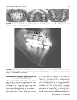
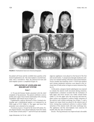
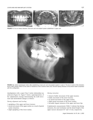
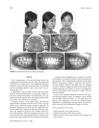
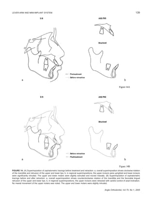
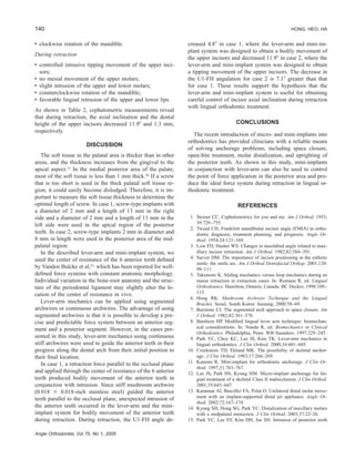
Angle Orthodontist, Vol 75, No 1, 2005129
Clinical Report
Lever-arm and Mini-implant System for Anterior Torque
Control during Retraction in Lingual Orthodontic Treatment
Ryoon-Ki Hong, DDS, PHDa
; Jung-Min Heo, DDSb
; Young-Ki Ha, DDSb
Abstract: Anterior torque control during retraction is difficult to achieve with lingual orthodontic treat-
ment. This article describes the use of a lever-arm and mini-implant system as absolute anchorage for
controlled retraction of the anterior teeth during lingual orthodontic treatment and evaluates 2 protrusion
cases treated with this system. Various clinical situations are discussed and analyzed from a biomechanical
standpoint. Mini-implants are needed to control the point of force application in the posterior area and
produce en masse retraction with no anchorage loss. When the length of the lever-arm is adjusted to the
position of the mini-implant, the desired line of action of the retraction force with respect to the center of
resistance of the anterior segment is selected. Controlled retraction of the anterior teeth was achieved with
no loss of anchorage. The mini-implant, in conjunction with the lever-arm, is useful not only for absolute
anchorage but also for anterior torque control during retraction in lingual orthodontic treatment. (Angle
Orthod 2004;75:129–141.)
Key Words: Controlled retraction, Absolute anchorage, Line of action of the retraction force, Center
of resistance
FIGURE 1. The effect of bracket position and location of the point
of force application on tooth movement. When the same amount of
retraction and intrusion forces is applied to the incisors in labial and
lingual systems, the resultant force in the lingual system is pointed
further away lingually from the center of resistance of the incisors
compared with the labial system. The net force in the lingual system
will produce a larger moment to tip the incisors lingually than in the
labial system. CR indicates center of resistance; FR, retraction force;
FI, intrusion force; FR ϩ I, resultant force; m and M, moment.
INTRODUCTION
Correct positioning of the maxillary and mandibular in-
cisors is essential for function, stability, and esthetics.1–4
Retraction of the incisors, therefore, represents a funda-
mental and often critical stage in orthodontic treatment. The
resultant movement of the incisors depends on the tissue
reaction produced by the applied biomechanical force sys-
tem.
In lingual orthodontic treatment, one of the most difficult
problems to overcome has been torque control of the an-
terior teeth during space closure (Figure 1).5,6
Anterior
torque control is achieved either by directly applying a mo-
ment and force to a lingual bracket or by using lever-arm
mechanics to obtain the desired line of action of the force
with respect to the center of resistance.7–9
In the lever-arm system, the desired tooth movement is
attained by adjusting the length of the lever-arm and the
point of force application. With labial appliances, the ex-
a
Chairman, Department of Orthodontics, Chong-A Dental Hospi-
tal, Seoul, South Korea.
b
Resident, Department of Orthodontics, Chong-A Dental Hospital,
Seoul, South Korea.
Corresponding author: Ryoon-Ki Hong, DDS, PHD, Department
of Orthodontics, Chong-A Dental Hospital, #648-22 Yoksam-Dong,
Gangnam-Gu, Seoul 135-080, South Korea (e-mail: kloa@kloa.co.kr).
Accepted: February 2004. Submitted: November 2003.
᭧ 2004 by The EH Angle Education and Research Foundation, Inc.
isting oral anatomy may prevent ideal placement of the le-
ver-arm system, but with lingual appliances, the lever-arm
system can always be ideally located because of the width
and depth of the palate. Therefore, lingual lever-arm me-
130 HONG, HEO, HA
Angle Orthodontist, Vol 75, No 1, 2005
FIGURE 2. Analysis of the reaction of the anterior teeth to different applications of the line of action of the retraction force. In all cases, a
0.018 ϫ 0.018-inch stainless steel mushroom archwire is placed from first molar to first molar in the upper arch, and 0.9 mm stainless steel
lever-arms are soldered onto the mushroom archwire between the lateral incisors and canines. The desired line of action of the retraction force
with respect to the center of resistance of the anterior segment is established by adjusting the length of the lever-arm and the position of the
mini-implant. The tendency toward translation or tipping and simultaneous extrusion or intrusion of the anterior teeth during retraction will be
determined by the direction of the retraction force. LA indicates lever-arm; MI, mini-implant; and CR, center of resistance of the anterior teeth.
(A) Force system for bodily movement of the anterior teeth: a, the anterior teeth will retract bodily and intrusively; b, the anterior teeth will
retract bodily; c, the anterior teeth will retract bodily and extrusively. (B) Force system for distal crown movement of the anterior teeth: a, the
crown of the anterior teeth will move distally and intrusively; b, the crown of the anterior teeth will move distally; c, the crown of the anterior
teeth will move distally and extrusively. (C) Force system for distal root movement of the anterior teeth: a, the root of the anterior teeth will
move distally and intrusively; b, the root of the anterior teeth will move distally; c, the root of the anterior teeth will move distally and extrusively.
chanics can be effective in achieving any desired tooth
movement.
Various types of dental implants including micro- or
miniscrews,10–15
miniplates,16,17
endosseous implants,18–21
and disc-shaped onplants22
have all been tested for anchor-
age in orthodontics. Micro- or miniscrews have advantages
over miniplates, cylindrical endosseous implants, and disc-
shaped onplants because of the ease of selecting proper im-
plant sites, ease of insertion in any desired location, ability
to withstand immediate force loading, and minimal irrita-
tion of the oral tissues.
The purpose of this study is to describe the lever-arm
and mini-implant system as absolute anchorage for con-
trolled retraction of the anterior teeth in lingual orthodontic
treatment and to demonstrate the effectiveness of this sys-
tem using clinical examples.
LEVER-ARM AND MINI-IMPLANT SYSTEM
Biomechanics
A number of different clinical situations may arise and
should be thoroughly analyzed from a biomechanical stand-
point to determine the correct force system necessary to
achieve the treatment objectives.
To design the optimal lever-arm and mini-implant system
for obtaining the desired force system during retraction, the
point of force application and the line of action of the re-
traction force are planned using lateral cephalograms. By
131LEVER-ARM AND MINI-IMPLANT SYSTEM
Angle Orthodontist, Vol 75, No 1, 2005
FIGURE 3. According to clinical situations, the length of the lever-arm and the position of the mini-implant are determined on the lateral
cephalogram. OP indicates occlusal plane; IPBL, interproximal bone level between the central incisors; CR, center of resistance of the 6
anterior teeth; LA, lever-arm; and GB, guide bar.
FIGURE 4. Intraoral photographs before (A) and after (B) establishing a lever-arm and mini-implant system.
adjusting the length of the lever-arm and the position of the
mini-implant, the desired line of action of the retraction
force with respect to the center of resistance of the anterior
segment is established.
The models in Figure 2 indicate the overall reaction that
can be expected in an average clinical application. A re-
traction force parallel to the occlusal plane and applied
through the center of resistance of the anterior teeth will
bodily retract the anterior segment (Figure 2Ab). In clinical
situations where the retraction is to be performed by trans-
lation and simultaneous intrusion, the retraction force is re-
directed through the center of resistance of the anterior teeth
as shown in Figure 2Aa. Figure 2Ac shows a configuration
that will result in translation and simultaneous extrusion.
The tendency toward lingual crown or lingual root move-
ment of the anterior teeth will be determined by the direc-
tion of the retraction force and notably by the rotational
effects derived from the relation of the line of action of the
retraction force relative to the center of resistance (Figure
2B,C). The correct design of the lever-arm and mini-
implant system is chosen after careful analysis of the clin-
ical situation.
132 HONG, HEO, HA
Angle Orthodontist, Vol 75, No 1, 2005
FIGURE 5. Pretreatment facial and intraoral photographs.
TABLE 1. Cephalometric Summary
Measurement Norms Pretreatment Before Retraction Posttreatment
Skeletal
SNA (Њ)
SNB (Њ)
ANB (Њ)
FMA (Њ)
NPo-FH (Њ)
82.3
78.9
3.4
28.8
84.8
88.0
83.6
4.4
35.6
89.4
88.3
83.7
4.6
35.9
89.7
88.1
83.2
4.8
35.5
89.7
Dental
Overbite (mm)
Overjet (mm)
1-FH (Њ)
FMIA (Њ)
Interincisal (Њ)
Is-IsЈ (mm)a
2.3
3.2
111.3
59.8
124.1
31.9
1.0
5.0
124.3
53.5
109.2
28.5
1.9
5.0
114.0
61.7
127.7
30.0
2.7
4.5
109.2
68.0
138.8
28.2
Soft tissue
Upper lip to E-line (mm)
Lower lip to E-line (mm)
Ϫ0.9
0.6
4.0
5.5
4.8
5.2
2.3
0.1
a
Is-IsЈ, indicates upper incisor dental height.
133LEVER-ARM AND MINI-IMPLANT SYSTEM
Angle Orthodontist, Vol 75, No 1, 2005
FIGURE 6. For en masse retraction, lever-arm and mini-implant system established in upper arch and 0.018 ϫ 0.018-inch stainless steel
closing-loop mushroom archwire placed in lower arch.
FIGURE 7. Lateral cephalogram taken after establishing a lever-arm and mini-implant system in case 1. The line of action of the retraction
force (LARF) passes through the center of resistance of the 6 anterior teeth (CR) and is parallel to the occlusal plane. In this case, bodily
retraction of the anterior teeth will be expected.
Determination of the length of the lever-arm and
the position of the mini-implant
The center of resistance of the unit to be moved is the
basic point for the arrangement of a force system. Vanden
Bulcke et al23
have concluded that the instantaneous center
of resistance for the 6 anterior teeth was located at 7.0 mm
apical to the interproximal bone level between the central
incisors (measured perpendicular to the occlusal plane).
Using the location of the center of resistance for the 6
anterior teeth defined by Vanden Bulcke et al, the length
of the lever-arm and the position of the mini-implant are
determined on the lateral cephalogram before retraction
(Figure 3). A lever-arm, made of 0.9 mm stainless steel
wire, is soldered onto the mushroom archwire between the
lateral incisors and canines and the fitting lever-arm length
is determined. The proper insertion site of the mini-implant
is measured from a guide bar made of 0.018 ϫ 0.018-inch
stainless steel wire and engaged in the molar bracket. The
mini-implants are inserted under local anesthesia directly
through the mucosa without any flap dissection. The fitting
implant length is determined by assessing the thickness of
134 HONG, HEO, HA
Angle Orthodontist, Vol 75, No 1, 2005
FIGURE 8. Posttreatment facial and intraoral photographs.
the palatal soft tissue and the available bone quantity at the
desired implantation site. The mini-implant is inserted man-
ually with a screwdriver. Then, the desired lever-arm and
mini-implant system is completed (Figure 4).
APPLICATION OF LEVER-ARM AND
MINI-IMPLANT SYSTEM
Case 1
A 25-year-old Korean female presented with the chief
complaint of lip protrusion. The patient exhibited a convex
profile and a super Class I molar relationship with a missing
mandibular right lateral incisor (Figure 5).
Cephalometric analysis disclosed a Class I skeletal rela-
tionship and a dolichofacial pattern, as evidenced by an
FMA angle of 35.6Њ (Table 1). The upper and lower first
premolars were selected to be extracted.
Treatment progress. Except for the lower left canine, Fu-
jita lingual brackets were placed indirectly from first molar
to first molar in both arches24,25
and 0.018-inch slot standard
edgewise appliances were placed on the buccal of the first
and second molars. A progression through mushroom arch-
wires was initiated starting with 0.012-inch nickel titanium.
Twelve months into treatment, 0.018 ϫ 0.018-inch stainless
steel closing mushroom archwires were placed in the oc-
clusal slots of both arches to begin en masse retraction (Fig-
ure 6).
At this point, a progress lateral cephalogram was exposed
to evaluate the anterior tooth movement during retraction.
Cephalometric evaluation revealed that the inclination of
both upper and lower incisors was within normal limits
(Table 1). For the upper arch, the lever-arm and mini-im-
plant system was designed to achieve bodily retraction of
the anterior teeth without anchorage loss (Figure 7), and a
lingual root torque bend was placed in the anterior part of
lower closing-loop mushroom archwire to achieve bodily
retraction of the anterior teeth with some anchorage loss.
The appliances and the mini-implants were removed 30
months after the start of treatment.
Results. The lip protrusion was improved and a favorable
135LEVER-ARM AND MINI-IMPLANT SYSTEM
Angle Orthodontist, Vol 75, No 1, 2005
FIGURE 9. (A) Superimposition of cephalometric tracings before treatment and retraction: a, overall superimposition shows no downward and
backward rotation of the mandible and augmentation of the nose. It seems that augmentation rhinoplasty was performed; b, in regional
superimpositions, the upper and lower incisors were uprighted. The upper molars moved mesially and the lower molars were slightly uprighted.
(B) Superimposition of cephalometric tracings before and after retraction: a, overall superimposition shows an improvement in lip relations,
with favorable lingual retrusion; b, in regional superimpositions, the upper incisors were retracted bodily and intrusively and the lower incisors
were bodily retracted. The upper molars did not move mesially at all and the lower molars slightly moved mesially.
136 HONG, HEO, HA
Angle Orthodontist, Vol 75, No 1, 2005
FIGURE 10. Pretreatment facial and intraoral photographs.
TABLE 2. Cephalometric Summary
Measurement Norms Pretreatment Before Retraction Posttreatment
Skeletal
SNA (Њ)
SNB (Њ)
ANB (Њ)
FMA (Њ)
NPo-FH (Њ)
82.3
78.9
3.4
28.8
84.8
80.4
76.8
3.6
21.1
89.9
80.3
75.8
4.5
22.0
89.2
79.5
76.1
3.4
20.7
89.5
Dental
Overbite (mm)
Overjet (mm)
1-FH (Њ)
FMIA (Њ)
Interincisal (Њ)
Is-IsЈ (mm)a
2.3
3.2
111.3
59.8
124.1
31.9
4.2
5.7
123.6
57.5
113.9
29.8
0.9
8.6
123.3
56.2
112.9
30.6
1.0
2.4
111.4
53.5
122.2
29.3
Soft tissue
Upper lip to E-line (mm)
Lower lip to E-line (mm)
Ϫ0.9
0.6
4.4
4.9
4.4
4.7
2.3
2.3
a
Is-IsЈ, indicates upper incisor dental height.
137LEVER-ARM AND MINI-IMPLANT SYSTEM
Angle Orthodontist, Vol 75, No 1, 2005
FIGURE 11. For en masse retraction, lever-arm and mini-implant system established in upper arch.
FIGURE 12. Lateral cephalogram taken after establishing a lever-arm and mini-implant system in case 2. The line of action of the retraction
force (LARF) passes inferior to the center of resistance of the 6 anterior teeth (CR). Intrusive tipping retraction of the anterior teeth is expected
with this configuration.
interdigitation with a super Class I molar relationship was
achieved (Figure 8). Figure 9 shows superimpositions of
the cephalometric tracings demonstrating the tooth move-
ment and skeletodental changes as follows:
During alignment and leveling
• uprighting of the upper and lower incisors;
• mesial movement of the upper molars as a result of partial
canine retraction;
• slight uprighting of the lower molars.
During retraction
• intrusive bodily movement of the upper incisors;
• bodily movement of the lower incisors;
• no mesial movement of the upper molars;
• slight mesial movement of the lower molars;
• favorable lingual retrusion of the upper and lower lips.
Cephalometric measurements (Table 1) indicate that during
retraction, the axial inclination and the dental height of the
upper incisors decreased 4.8Њ and 1.8 mm, respectively.
138 HONG, HEO, HA
Angle Orthodontist, Vol 75, No 1, 2005
FIGURE 13. Posttreatment facial and intraoral photographs.
Case 2
Case 2 demonstrates a 22-year-old Korean female who
complained of lip protrusion and crowding. The patient had
a skeletal Class I malocclusion. The mandibular permanent
left lateral incisor and right second premolar were missing,
and the mandibular primary right second molar was re-
tained (Figure 10).
Cephalometric analysis (Table 2) shows that the antero-
posterior skeletal measurements were generally within nor-
mal limits and the facial pattern was brachyfacial. The up-
per first premolars and the lower prolonged retained decid-
uous molar were selected to be extracted.
Treatment progress. In the initial stage, upper anterior
lingual brackets interfered with the lower incisors when the
patient was in occlusion, causing a posterior open bite. To
avoid this interference, the lower arch was indirectly bond-
ed and banded first. Progression through mushroom arch-
wires was initiated in the lower arch, starting with 0.012-
inch nickel titanium. After bite opening by intrusion of the
lower anterior teeth, Fujita lingual brackets were placed in-
directly from upper right first molar to upper left first molar.
A progress lateral cephalogram was exposed 18 months
into treatment to evaluate the anterior tooth movement dur-
ing retraction. This revealed that the inclination of the upper
incisors was protrusive (Table 2). Therefore, the lever-arm
and mini-implant system for the upper arch was designed
to achieve intrusive tipping retraction of the anterior teeth
without anchorage loss (Figures 11 and 12). The appliances
and the mini-implants were removed 33 months after the
start of treatment.
Results. After lingual orthodontic treatment with lever-
arm and mini-implant system, the patient’s convex profile
was favorably improved (Figure 13). The teeth were well
aligned, and a satisfactory occlusion was achieved. Super-
impositions of cephalometric tracings (Figure 14) show the
tooth movement and skeletodental changes as follows:
During alignment and leveling
• slight uprighting of the upper incisors;
• significant intrusion of the lower incisors;
• slight extrusion and mesial movement of the upper and
lower molars;
139LEVER-ARM AND MINI-IMPLANT SYSTEM
Angle Orthodontist, Vol 75, No 1, 2005
FIGURE 14. (A) Superimposition of cephalometric tracings before treatment and retraction: a, overall superimposition shows clockwise rotation
of the mandible and retrusion of the upper and lower lips; b, in regional superimpositions, the upper incisors were uprighted and lower incisors
were significantly intruded. The upper and lower molars were slightly extruded and moved mesially. (B) Superimposition of cephalometric
tracings before and after retraction: a, overall superimposition shows counterclockwise rotation of the mandible and the favorable lingual
retrusion of the upper and lower lips; b, in regional superimpositions, the upper incisors were retracted with careful control of axial inclination.
No mesial movement of the upper molars was noted. The upper and lower molars were slightly intruded.
140 HONG, HEO, HA
Angle Orthodontist, Vol 75, No 1, 2005
• clockwise rotation of the mandible.
During retraction
• controlled intrusive tipping movement of the upper inci-
sors;
• no mesial movement of the upper molars;
• slight intrusion of the upper and lower molars;
• counterclockwise rotation of the mandible;
• favorable lingual retrusion of the upper and lower lips.
As shown in Table 2, cephalometric measurements reveal
that during retraction, the axial inclination and the dental
height of the upper incisors decreased 11.9Њ and 1.3 mm,
respectively.
DISCUSSION
The soft tissue in the palatal area is thicker than in other
areas, and the thickness increases from the gingival to the
apical aspect.15
In the medial posterior area of the palate,
most of the soft tissue is less than 1 mm thick.26
If a screw
that is too short is used in the thick palatal soft tissue re-
gion, it could easily become dislodged. Therefore, it is im-
portant to measure the soft tissue thickness to determine the
optimal length of screw. In case 1, screw-type implants with
a diameter of 2 mm and a length of 13 mm in the right
side and a diameter of 2 mm and a length of 11 mm in the
left side were used in the apical region of the posterior
teeth. In case 2, screw-type implants 2 mm in diameter and
8 mm in length were used in the posterior area of the mid-
palatal region.
In the described lever-arm and mini-implant system, we
used the center of resistance of the 6 anterior teeth defined
by Vanden Bulcke et al,23,
which has been reported for well-
defined force systems with constant anatomic morphology.
Individual variation in the bone-root anatomy and the struc-
ture of the periodontal ligament may slightly alter the lo-
cation of the center of resistance in vivo.
Lever-arm mechanics can be applied using segmented
archwires or continuous archwires. The advantage of using
segmented archwires is that it is possible to develop a pre-
cise and predictable force system between an anterior seg-
ment and a posterior segment. However, in the cases pre-
sented in this study, lever-arm mechanics using continuous
stiff archwires were used to guide the anterior teeth in their
progress along the dental arch from their initial position to
their final location.
In case 1, a retraction force parallel to the occlusal plane
and applied through the center of resistance of the 6 anterior
teeth produced bodily movement of the anterior teeth in
conjunction with intrusion. Since stiff mushroom archwire
(0.018 ϫ 0.018-inch stainless steel) guided the anterior
teeth parallel to the occlusal plane, unexpected intrusion of
the anterior teeth occurred in the lever-arm and the mini-
implant system for bodily movement of the anterior teeth
during retraction. During retraction, the U1-FH angle de-
creased 4.8Њ in case 1, where the lever-arm and mini-im-
plant system was designed to obtain a bodily movement of
the upper incisors and decreased 11.9Њ in case 2, where the
lever-arm and mini-implant system was designed to obtain
a tipping movement of the upper incisors. The decrease in
the U1-FH angulation for case 2 is 7.1Њ greater than that
for case 1. These results support the hypothesis that the
lever-arm and mini-implant system is useful for obtaining
careful control of incisor axial inclination during retraction
with lingual orthodontic treatment.
CONCLUSIONS
The recent introduction of micro- and mini-implants into
orthodontics has provided clinicians with a reliable means
of solving anchorage problems, including space closure,
open-bite treatment, molar distalization, and uprighting of
the posterior teeth. As shown in this study, mini-implants
in conjunction with lever-arm can also be used to control
the point of force application in the posterior area and pro-
duce the ideal force system during retraction in lingual or-
thodontic treatment.
REFERENCES
1. Steiner CC. Cephalometrics for you and me. Am J Orthod. 1953;
39:729–755.
2. Tweed CH. Frankfort mandibular incisor angle (FMIA) in ortho-
dontic diagnosis, treatment planning, and prognosis. Angle Or-
thod. 1954;24:121–169.
3. Low FD, Hunter WS. Changes in nasolabial angle related to max-
illary incisor retraction. Am J Orthod. 1982;82:384–391.
4. Sarver DM. The importance of incisor positioning in the esthetic
smile: the smile arc. Am J Orthod Dentofacial Orthop. 2001;120:
98–111.
5. Takemoto K. Sliding mechanics versus loop mechanics during en
masse retraction in extraction cases. In: Romano R, ed. Lingual
Orthodontics. Hamilton, Ontario, Canada: BC Decker; 1998:109–
115.
6. Hong RK. Mushroom Archwire Technique and the Lingual
Bracket. Seoul, South Korea: Jeesung; 2000:58–69.
7. Burstone CJ. The segmented arch approach to space closure. Am
J Orthod. 1982;82:361–378.
8. Bantleon HP. Modified lingual lever arm technique: biomechan-
ical considerations. In: Nanda R, ed. Biomechanics in Clinical
Orthodontics. Philadelphia, Penn: WB Saunders; 1997:229–245.
9. Park YC, Choy KC, Lee JS, Kim TK. Lever-arm mechanics in
lingual orthodontics. J Clin Orthod. 2000;34:601–605.
10. Creekmore TD, Eklund MK. The possibility of skeletal anchor-
age. J Clin Orthod. 1983;17:266–269.
11. Kanomi R. Mini-implant for orthodontic anchorage. J Clin Or-
thod. 1997;31:763–767.
12. Lee JS, Park HS, Kyung HM. Micro-implant anchorage for lin-
gual treatment of a skeletal Class II malocclusion. J Clin Orthod.
2001;35:643–647.
13. Karaman AI, Basciftci FA, Polat O. Unilateral distal molar move-
ment with an implant-supported distal jet appliance. Angle Or-
thod. 2002;72:167–174.
14. Kyung SH, Hong SG, Park YC. Distalization of maxillary molars
with a midpalatal miniscrew. J Clin Orthod. 2003;37:22–26.
15. Park YC, Lee SY, Kim DH, Jee SH. Intrusion of posterior teeth
141LEVER-ARM AND MINI-IMPLANT SYSTEM
Angle Orthodontist, Vol 75, No 1, 2005
using mini-screw implants. Am J Orthod Dentofacial Orthop.
2003;123:690–694.
16. Umemori M, Sugawara J, Mitani H, Nagasaka H, Kawamura H.
Skeletal anchorage system for open-bite correction. Am J Orthod
Dentofacial Orthop. 1999;115:166–174.
17. Chung KR, Kim YS, Lee Linton J, Lee YJ. The miniplate with
tube for skeletal anchorage. J Clin Orthod. 2002;36:407–412.
18. Roberts WE, Smith RK, Zilberman Y, Mozsary PG, Smith RS.
Osseous adaptation to continuous loading of rigid endosseous im-
plants. Am J Orthod. 1984;86:95–111.
19. Roberts WE, Helm FR, Marshall KJ, Gongloff RK. Rigid endos-
seous implants for orthodontic and orthopedic anchorage. Angle
Orthod. 1989;59:247–255.
20. O¨ dman J, Lekholm U, Jemt T, Thilander B. Osseointegrated im-
plants as orthodontic anchorage in treatment of partially edentu-
lous adult patients. Eur J Orthod. 1994;16:187–201.
21. Wehrbein H, Feifel H, Diedrich P. Palatal implant anchorage re-
inforcement of posterior teeth: a prospective study. Am J Orthod
Dentofacial Orthop. 1999;116:678–686.
22. Block MS, Hoffman DR. A new device for absolute anchorage
for orthodontics. Am J Orthod Dentofacial Orthop. 1995;107:
251–258.
23. Vanden Bulcke MM, Burstone CJ, Sachdeva RCL, Dermaut LR.
Location of the centers of resistance for anterior teeth during re-
traction using the laser reflection technique. Am J Orthod Den-
tofacial Orthop. 1987;91:375–384.
24. Hong RK, Sohn HW. Update on the Fujita lingual bracket. J Clin
Orthod. 1999;33:136–142.
25. Hong RK, Soh BC. Customized indirect bonding method for lin-
gual orthodontics. J Clin Orthod. 1996;30:650–652.
26. Yun HS, Kim HJ, Kim KH, Park YC. The Thickness of the Max-
illary Soft Tissue and Cortical Bone Related with an Orthodontic
Implantation. Master’s Thesis. Seoul, South Korea: Yonsei Uni-
versity; 2001.

잇몸돌출입과 라미교정술식 Ao article

  • 1.
    Angle Orthodontist, Vol75, No 1, 2005129 Clinical Report Lever-arm and Mini-implant System for Anterior Torque Control during Retraction in Lingual Orthodontic Treatment Ryoon-Ki Hong, DDS, PHDa ; Jung-Min Heo, DDSb ; Young-Ki Ha, DDSb Abstract: Anterior torque control during retraction is difficult to achieve with lingual orthodontic treat- ment. This article describes the use of a lever-arm and mini-implant system as absolute anchorage for controlled retraction of the anterior teeth during lingual orthodontic treatment and evaluates 2 protrusion cases treated with this system. Various clinical situations are discussed and analyzed from a biomechanical standpoint. Mini-implants are needed to control the point of force application in the posterior area and produce en masse retraction with no anchorage loss. When the length of the lever-arm is adjusted to the position of the mini-implant, the desired line of action of the retraction force with respect to the center of resistance of the anterior segment is selected. Controlled retraction of the anterior teeth was achieved with no loss of anchorage. The mini-implant, in conjunction with the lever-arm, is useful not only for absolute anchorage but also for anterior torque control during retraction in lingual orthodontic treatment. (Angle Orthod 2004;75:129–141.) Key Words: Controlled retraction, Absolute anchorage, Line of action of the retraction force, Center of resistance FIGURE 1. The effect of bracket position and location of the point of force application on tooth movement. When the same amount of retraction and intrusion forces is applied to the incisors in labial and lingual systems, the resultant force in the lingual system is pointed further away lingually from the center of resistance of the incisors compared with the labial system. The net force in the lingual system will produce a larger moment to tip the incisors lingually than in the labial system. CR indicates center of resistance; FR, retraction force; FI, intrusion force; FR ϩ I, resultant force; m and M, moment. INTRODUCTION Correct positioning of the maxillary and mandibular in- cisors is essential for function, stability, and esthetics.1–4 Retraction of the incisors, therefore, represents a funda- mental and often critical stage in orthodontic treatment. The resultant movement of the incisors depends on the tissue reaction produced by the applied biomechanical force sys- tem. In lingual orthodontic treatment, one of the most difficult problems to overcome has been torque control of the an- terior teeth during space closure (Figure 1).5,6 Anterior torque control is achieved either by directly applying a mo- ment and force to a lingual bracket or by using lever-arm mechanics to obtain the desired line of action of the force with respect to the center of resistance.7–9 In the lever-arm system, the desired tooth movement is attained by adjusting the length of the lever-arm and the point of force application. With labial appliances, the ex- a Chairman, Department of Orthodontics, Chong-A Dental Hospi- tal, Seoul, South Korea. b Resident, Department of Orthodontics, Chong-A Dental Hospital, Seoul, South Korea. Corresponding author: Ryoon-Ki Hong, DDS, PHD, Department of Orthodontics, Chong-A Dental Hospital, #648-22 Yoksam-Dong, Gangnam-Gu, Seoul 135-080, South Korea (e-mail: kloa@kloa.co.kr). Accepted: February 2004. Submitted: November 2003. ᭧ 2004 by The EH Angle Education and Research Foundation, Inc. isting oral anatomy may prevent ideal placement of the le- ver-arm system, but with lingual appliances, the lever-arm system can always be ideally located because of the width and depth of the palate. Therefore, lingual lever-arm me-
  • 2.
    130 HONG, HEO,HA Angle Orthodontist, Vol 75, No 1, 2005 FIGURE 2. Analysis of the reaction of the anterior teeth to different applications of the line of action of the retraction force. In all cases, a 0.018 ϫ 0.018-inch stainless steel mushroom archwire is placed from first molar to first molar in the upper arch, and 0.9 mm stainless steel lever-arms are soldered onto the mushroom archwire between the lateral incisors and canines. The desired line of action of the retraction force with respect to the center of resistance of the anterior segment is established by adjusting the length of the lever-arm and the position of the mini-implant. The tendency toward translation or tipping and simultaneous extrusion or intrusion of the anterior teeth during retraction will be determined by the direction of the retraction force. LA indicates lever-arm; MI, mini-implant; and CR, center of resistance of the anterior teeth. (A) Force system for bodily movement of the anterior teeth: a, the anterior teeth will retract bodily and intrusively; b, the anterior teeth will retract bodily; c, the anterior teeth will retract bodily and extrusively. (B) Force system for distal crown movement of the anterior teeth: a, the crown of the anterior teeth will move distally and intrusively; b, the crown of the anterior teeth will move distally; c, the crown of the anterior teeth will move distally and extrusively. (C) Force system for distal root movement of the anterior teeth: a, the root of the anterior teeth will move distally and intrusively; b, the root of the anterior teeth will move distally; c, the root of the anterior teeth will move distally and extrusively. chanics can be effective in achieving any desired tooth movement. Various types of dental implants including micro- or miniscrews,10–15 miniplates,16,17 endosseous implants,18–21 and disc-shaped onplants22 have all been tested for anchor- age in orthodontics. Micro- or miniscrews have advantages over miniplates, cylindrical endosseous implants, and disc- shaped onplants because of the ease of selecting proper im- plant sites, ease of insertion in any desired location, ability to withstand immediate force loading, and minimal irrita- tion of the oral tissues. The purpose of this study is to describe the lever-arm and mini-implant system as absolute anchorage for con- trolled retraction of the anterior teeth in lingual orthodontic treatment and to demonstrate the effectiveness of this sys- tem using clinical examples. LEVER-ARM AND MINI-IMPLANT SYSTEM Biomechanics A number of different clinical situations may arise and should be thoroughly analyzed from a biomechanical stand- point to determine the correct force system necessary to achieve the treatment objectives. To design the optimal lever-arm and mini-implant system for obtaining the desired force system during retraction, the point of force application and the line of action of the re- traction force are planned using lateral cephalograms. By
  • 3.
    131LEVER-ARM AND MINI-IMPLANTSYSTEM Angle Orthodontist, Vol 75, No 1, 2005 FIGURE 3. According to clinical situations, the length of the lever-arm and the position of the mini-implant are determined on the lateral cephalogram. OP indicates occlusal plane; IPBL, interproximal bone level between the central incisors; CR, center of resistance of the 6 anterior teeth; LA, lever-arm; and GB, guide bar. FIGURE 4. Intraoral photographs before (A) and after (B) establishing a lever-arm and mini-implant system. adjusting the length of the lever-arm and the position of the mini-implant, the desired line of action of the retraction force with respect to the center of resistance of the anterior segment is established. The models in Figure 2 indicate the overall reaction that can be expected in an average clinical application. A re- traction force parallel to the occlusal plane and applied through the center of resistance of the anterior teeth will bodily retract the anterior segment (Figure 2Ab). In clinical situations where the retraction is to be performed by trans- lation and simultaneous intrusion, the retraction force is re- directed through the center of resistance of the anterior teeth as shown in Figure 2Aa. Figure 2Ac shows a configuration that will result in translation and simultaneous extrusion. The tendency toward lingual crown or lingual root move- ment of the anterior teeth will be determined by the direc- tion of the retraction force and notably by the rotational effects derived from the relation of the line of action of the retraction force relative to the center of resistance (Figure 2B,C). The correct design of the lever-arm and mini- implant system is chosen after careful analysis of the clin- ical situation.
  • 4.
    132 HONG, HEO,HA Angle Orthodontist, Vol 75, No 1, 2005 FIGURE 5. Pretreatment facial and intraoral photographs. TABLE 1. Cephalometric Summary Measurement Norms Pretreatment Before Retraction Posttreatment Skeletal SNA (Њ) SNB (Њ) ANB (Њ) FMA (Њ) NPo-FH (Њ) 82.3 78.9 3.4 28.8 84.8 88.0 83.6 4.4 35.6 89.4 88.3 83.7 4.6 35.9 89.7 88.1 83.2 4.8 35.5 89.7 Dental Overbite (mm) Overjet (mm) 1-FH (Њ) FMIA (Њ) Interincisal (Њ) Is-IsЈ (mm)a 2.3 3.2 111.3 59.8 124.1 31.9 1.0 5.0 124.3 53.5 109.2 28.5 1.9 5.0 114.0 61.7 127.7 30.0 2.7 4.5 109.2 68.0 138.8 28.2 Soft tissue Upper lip to E-line (mm) Lower lip to E-line (mm) Ϫ0.9 0.6 4.0 5.5 4.8 5.2 2.3 0.1 a Is-IsЈ, indicates upper incisor dental height.
  • 5.
    133LEVER-ARM AND MINI-IMPLANTSYSTEM Angle Orthodontist, Vol 75, No 1, 2005 FIGURE 6. For en masse retraction, lever-arm and mini-implant system established in upper arch and 0.018 ϫ 0.018-inch stainless steel closing-loop mushroom archwire placed in lower arch. FIGURE 7. Lateral cephalogram taken after establishing a lever-arm and mini-implant system in case 1. The line of action of the retraction force (LARF) passes through the center of resistance of the 6 anterior teeth (CR) and is parallel to the occlusal plane. In this case, bodily retraction of the anterior teeth will be expected. Determination of the length of the lever-arm and the position of the mini-implant The center of resistance of the unit to be moved is the basic point for the arrangement of a force system. Vanden Bulcke et al23 have concluded that the instantaneous center of resistance for the 6 anterior teeth was located at 7.0 mm apical to the interproximal bone level between the central incisors (measured perpendicular to the occlusal plane). Using the location of the center of resistance for the 6 anterior teeth defined by Vanden Bulcke et al, the length of the lever-arm and the position of the mini-implant are determined on the lateral cephalogram before retraction (Figure 3). A lever-arm, made of 0.9 mm stainless steel wire, is soldered onto the mushroom archwire between the lateral incisors and canines and the fitting lever-arm length is determined. The proper insertion site of the mini-implant is measured from a guide bar made of 0.018 ϫ 0.018-inch stainless steel wire and engaged in the molar bracket. The mini-implants are inserted under local anesthesia directly through the mucosa without any flap dissection. The fitting implant length is determined by assessing the thickness of
  • 6.
    134 HONG, HEO,HA Angle Orthodontist, Vol 75, No 1, 2005 FIGURE 8. Posttreatment facial and intraoral photographs. the palatal soft tissue and the available bone quantity at the desired implantation site. The mini-implant is inserted man- ually with a screwdriver. Then, the desired lever-arm and mini-implant system is completed (Figure 4). APPLICATION OF LEVER-ARM AND MINI-IMPLANT SYSTEM Case 1 A 25-year-old Korean female presented with the chief complaint of lip protrusion. The patient exhibited a convex profile and a super Class I molar relationship with a missing mandibular right lateral incisor (Figure 5). Cephalometric analysis disclosed a Class I skeletal rela- tionship and a dolichofacial pattern, as evidenced by an FMA angle of 35.6Њ (Table 1). The upper and lower first premolars were selected to be extracted. Treatment progress. Except for the lower left canine, Fu- jita lingual brackets were placed indirectly from first molar to first molar in both arches24,25 and 0.018-inch slot standard edgewise appliances were placed on the buccal of the first and second molars. A progression through mushroom arch- wires was initiated starting with 0.012-inch nickel titanium. Twelve months into treatment, 0.018 ϫ 0.018-inch stainless steel closing mushroom archwires were placed in the oc- clusal slots of both arches to begin en masse retraction (Fig- ure 6). At this point, a progress lateral cephalogram was exposed to evaluate the anterior tooth movement during retraction. Cephalometric evaluation revealed that the inclination of both upper and lower incisors was within normal limits (Table 1). For the upper arch, the lever-arm and mini-im- plant system was designed to achieve bodily retraction of the anterior teeth without anchorage loss (Figure 7), and a lingual root torque bend was placed in the anterior part of lower closing-loop mushroom archwire to achieve bodily retraction of the anterior teeth with some anchorage loss. The appliances and the mini-implants were removed 30 months after the start of treatment. Results. The lip protrusion was improved and a favorable
  • 7.
    135LEVER-ARM AND MINI-IMPLANTSYSTEM Angle Orthodontist, Vol 75, No 1, 2005 FIGURE 9. (A) Superimposition of cephalometric tracings before treatment and retraction: a, overall superimposition shows no downward and backward rotation of the mandible and augmentation of the nose. It seems that augmentation rhinoplasty was performed; b, in regional superimpositions, the upper and lower incisors were uprighted. The upper molars moved mesially and the lower molars were slightly uprighted. (B) Superimposition of cephalometric tracings before and after retraction: a, overall superimposition shows an improvement in lip relations, with favorable lingual retrusion; b, in regional superimpositions, the upper incisors were retracted bodily and intrusively and the lower incisors were bodily retracted. The upper molars did not move mesially at all and the lower molars slightly moved mesially.
  • 8.
    136 HONG, HEO,HA Angle Orthodontist, Vol 75, No 1, 2005 FIGURE 10. Pretreatment facial and intraoral photographs. TABLE 2. Cephalometric Summary Measurement Norms Pretreatment Before Retraction Posttreatment Skeletal SNA (Њ) SNB (Њ) ANB (Њ) FMA (Њ) NPo-FH (Њ) 82.3 78.9 3.4 28.8 84.8 80.4 76.8 3.6 21.1 89.9 80.3 75.8 4.5 22.0 89.2 79.5 76.1 3.4 20.7 89.5 Dental Overbite (mm) Overjet (mm) 1-FH (Њ) FMIA (Њ) Interincisal (Њ) Is-IsЈ (mm)a 2.3 3.2 111.3 59.8 124.1 31.9 4.2 5.7 123.6 57.5 113.9 29.8 0.9 8.6 123.3 56.2 112.9 30.6 1.0 2.4 111.4 53.5 122.2 29.3 Soft tissue Upper lip to E-line (mm) Lower lip to E-line (mm) Ϫ0.9 0.6 4.4 4.9 4.4 4.7 2.3 2.3 a Is-IsЈ, indicates upper incisor dental height.
  • 9.
    137LEVER-ARM AND MINI-IMPLANTSYSTEM Angle Orthodontist, Vol 75, No 1, 2005 FIGURE 11. For en masse retraction, lever-arm and mini-implant system established in upper arch. FIGURE 12. Lateral cephalogram taken after establishing a lever-arm and mini-implant system in case 2. The line of action of the retraction force (LARF) passes inferior to the center of resistance of the 6 anterior teeth (CR). Intrusive tipping retraction of the anterior teeth is expected with this configuration. interdigitation with a super Class I molar relationship was achieved (Figure 8). Figure 9 shows superimpositions of the cephalometric tracings demonstrating the tooth move- ment and skeletodental changes as follows: During alignment and leveling • uprighting of the upper and lower incisors; • mesial movement of the upper molars as a result of partial canine retraction; • slight uprighting of the lower molars. During retraction • intrusive bodily movement of the upper incisors; • bodily movement of the lower incisors; • no mesial movement of the upper molars; • slight mesial movement of the lower molars; • favorable lingual retrusion of the upper and lower lips. Cephalometric measurements (Table 1) indicate that during retraction, the axial inclination and the dental height of the upper incisors decreased 4.8Њ and 1.8 mm, respectively.
  • 10.
    138 HONG, HEO,HA Angle Orthodontist, Vol 75, No 1, 2005 FIGURE 13. Posttreatment facial and intraoral photographs. Case 2 Case 2 demonstrates a 22-year-old Korean female who complained of lip protrusion and crowding. The patient had a skeletal Class I malocclusion. The mandibular permanent left lateral incisor and right second premolar were missing, and the mandibular primary right second molar was re- tained (Figure 10). Cephalometric analysis (Table 2) shows that the antero- posterior skeletal measurements were generally within nor- mal limits and the facial pattern was brachyfacial. The up- per first premolars and the lower prolonged retained decid- uous molar were selected to be extracted. Treatment progress. In the initial stage, upper anterior lingual brackets interfered with the lower incisors when the patient was in occlusion, causing a posterior open bite. To avoid this interference, the lower arch was indirectly bond- ed and banded first. Progression through mushroom arch- wires was initiated in the lower arch, starting with 0.012- inch nickel titanium. After bite opening by intrusion of the lower anterior teeth, Fujita lingual brackets were placed in- directly from upper right first molar to upper left first molar. A progress lateral cephalogram was exposed 18 months into treatment to evaluate the anterior tooth movement dur- ing retraction. This revealed that the inclination of the upper incisors was protrusive (Table 2). Therefore, the lever-arm and mini-implant system for the upper arch was designed to achieve intrusive tipping retraction of the anterior teeth without anchorage loss (Figures 11 and 12). The appliances and the mini-implants were removed 33 months after the start of treatment. Results. After lingual orthodontic treatment with lever- arm and mini-implant system, the patient’s convex profile was favorably improved (Figure 13). The teeth were well aligned, and a satisfactory occlusion was achieved. Super- impositions of cephalometric tracings (Figure 14) show the tooth movement and skeletodental changes as follows: During alignment and leveling • slight uprighting of the upper incisors; • significant intrusion of the lower incisors; • slight extrusion and mesial movement of the upper and lower molars;
  • 11.
    139LEVER-ARM AND MINI-IMPLANTSYSTEM Angle Orthodontist, Vol 75, No 1, 2005 FIGURE 14. (A) Superimposition of cephalometric tracings before treatment and retraction: a, overall superimposition shows clockwise rotation of the mandible and retrusion of the upper and lower lips; b, in regional superimpositions, the upper incisors were uprighted and lower incisors were significantly intruded. The upper and lower molars were slightly extruded and moved mesially. (B) Superimposition of cephalometric tracings before and after retraction: a, overall superimposition shows counterclockwise rotation of the mandible and the favorable lingual retrusion of the upper and lower lips; b, in regional superimpositions, the upper incisors were retracted with careful control of axial inclination. No mesial movement of the upper molars was noted. The upper and lower molars were slightly intruded.
  • 12.
    140 HONG, HEO,HA Angle Orthodontist, Vol 75, No 1, 2005 • clockwise rotation of the mandible. During retraction • controlled intrusive tipping movement of the upper inci- sors; • no mesial movement of the upper molars; • slight intrusion of the upper and lower molars; • counterclockwise rotation of the mandible; • favorable lingual retrusion of the upper and lower lips. As shown in Table 2, cephalometric measurements reveal that during retraction, the axial inclination and the dental height of the upper incisors decreased 11.9Њ and 1.3 mm, respectively. DISCUSSION The soft tissue in the palatal area is thicker than in other areas, and the thickness increases from the gingival to the apical aspect.15 In the medial posterior area of the palate, most of the soft tissue is less than 1 mm thick.26 If a screw that is too short is used in the thick palatal soft tissue re- gion, it could easily become dislodged. Therefore, it is im- portant to measure the soft tissue thickness to determine the optimal length of screw. In case 1, screw-type implants with a diameter of 2 mm and a length of 13 mm in the right side and a diameter of 2 mm and a length of 11 mm in the left side were used in the apical region of the posterior teeth. In case 2, screw-type implants 2 mm in diameter and 8 mm in length were used in the posterior area of the mid- palatal region. In the described lever-arm and mini-implant system, we used the center of resistance of the 6 anterior teeth defined by Vanden Bulcke et al,23, which has been reported for well- defined force systems with constant anatomic morphology. Individual variation in the bone-root anatomy and the struc- ture of the periodontal ligament may slightly alter the lo- cation of the center of resistance in vivo. Lever-arm mechanics can be applied using segmented archwires or continuous archwires. The advantage of using segmented archwires is that it is possible to develop a pre- cise and predictable force system between an anterior seg- ment and a posterior segment. However, in the cases pre- sented in this study, lever-arm mechanics using continuous stiff archwires were used to guide the anterior teeth in their progress along the dental arch from their initial position to their final location. In case 1, a retraction force parallel to the occlusal plane and applied through the center of resistance of the 6 anterior teeth produced bodily movement of the anterior teeth in conjunction with intrusion. Since stiff mushroom archwire (0.018 ϫ 0.018-inch stainless steel) guided the anterior teeth parallel to the occlusal plane, unexpected intrusion of the anterior teeth occurred in the lever-arm and the mini- implant system for bodily movement of the anterior teeth during retraction. During retraction, the U1-FH angle de- creased 4.8Њ in case 1, where the lever-arm and mini-im- plant system was designed to obtain a bodily movement of the upper incisors and decreased 11.9Њ in case 2, where the lever-arm and mini-implant system was designed to obtain a tipping movement of the upper incisors. The decrease in the U1-FH angulation for case 2 is 7.1Њ greater than that for case 1. These results support the hypothesis that the lever-arm and mini-implant system is useful for obtaining careful control of incisor axial inclination during retraction with lingual orthodontic treatment. CONCLUSIONS The recent introduction of micro- and mini-implants into orthodontics has provided clinicians with a reliable means of solving anchorage problems, including space closure, open-bite treatment, molar distalization, and uprighting of the posterior teeth. As shown in this study, mini-implants in conjunction with lever-arm can also be used to control the point of force application in the posterior area and pro- duce the ideal force system during retraction in lingual or- thodontic treatment. REFERENCES 1. Steiner CC. Cephalometrics for you and me. Am J Orthod. 1953; 39:729–755. 2. Tweed CH. Frankfort mandibular incisor angle (FMIA) in ortho- dontic diagnosis, treatment planning, and prognosis. Angle Or- thod. 1954;24:121–169. 3. Low FD, Hunter WS. Changes in nasolabial angle related to max- illary incisor retraction. Am J Orthod. 1982;82:384–391. 4. Sarver DM. The importance of incisor positioning in the esthetic smile: the smile arc. Am J Orthod Dentofacial Orthop. 2001;120: 98–111. 5. Takemoto K. Sliding mechanics versus loop mechanics during en masse retraction in extraction cases. In: Romano R, ed. Lingual Orthodontics. Hamilton, Ontario, Canada: BC Decker; 1998:109– 115. 6. Hong RK. Mushroom Archwire Technique and the Lingual Bracket. Seoul, South Korea: Jeesung; 2000:58–69. 7. Burstone CJ. The segmented arch approach to space closure. Am J Orthod. 1982;82:361–378. 8. Bantleon HP. Modified lingual lever arm technique: biomechan- ical considerations. In: Nanda R, ed. Biomechanics in Clinical Orthodontics. Philadelphia, Penn: WB Saunders; 1997:229–245. 9. Park YC, Choy KC, Lee JS, Kim TK. Lever-arm mechanics in lingual orthodontics. J Clin Orthod. 2000;34:601–605. 10. Creekmore TD, Eklund MK. The possibility of skeletal anchor- age. J Clin Orthod. 1983;17:266–269. 11. Kanomi R. Mini-implant for orthodontic anchorage. J Clin Or- thod. 1997;31:763–767. 12. Lee JS, Park HS, Kyung HM. Micro-implant anchorage for lin- gual treatment of a skeletal Class II malocclusion. J Clin Orthod. 2001;35:643–647. 13. Karaman AI, Basciftci FA, Polat O. Unilateral distal molar move- ment with an implant-supported distal jet appliance. Angle Or- thod. 2002;72:167–174. 14. Kyung SH, Hong SG, Park YC. Distalization of maxillary molars with a midpalatal miniscrew. J Clin Orthod. 2003;37:22–26. 15. Park YC, Lee SY, Kim DH, Jee SH. Intrusion of posterior teeth
  • 13.
    141LEVER-ARM AND MINI-IMPLANTSYSTEM Angle Orthodontist, Vol 75, No 1, 2005 using mini-screw implants. Am J Orthod Dentofacial Orthop. 2003;123:690–694. 16. Umemori M, Sugawara J, Mitani H, Nagasaka H, Kawamura H. Skeletal anchorage system for open-bite correction. Am J Orthod Dentofacial Orthop. 1999;115:166–174. 17. Chung KR, Kim YS, Lee Linton J, Lee YJ. The miniplate with tube for skeletal anchorage. J Clin Orthod. 2002;36:407–412. 18. Roberts WE, Smith RK, Zilberman Y, Mozsary PG, Smith RS. Osseous adaptation to continuous loading of rigid endosseous im- plants. Am J Orthod. 1984;86:95–111. 19. Roberts WE, Helm FR, Marshall KJ, Gongloff RK. Rigid endos- seous implants for orthodontic and orthopedic anchorage. Angle Orthod. 1989;59:247–255. 20. O¨ dman J, Lekholm U, Jemt T, Thilander B. Osseointegrated im- plants as orthodontic anchorage in treatment of partially edentu- lous adult patients. Eur J Orthod. 1994;16:187–201. 21. Wehrbein H, Feifel H, Diedrich P. Palatal implant anchorage re- inforcement of posterior teeth: a prospective study. Am J Orthod Dentofacial Orthop. 1999;116:678–686. 22. Block MS, Hoffman DR. A new device for absolute anchorage for orthodontics. Am J Orthod Dentofacial Orthop. 1995;107: 251–258. 23. Vanden Bulcke MM, Burstone CJ, Sachdeva RCL, Dermaut LR. Location of the centers of resistance for anterior teeth during re- traction using the laser reflection technique. Am J Orthod Den- tofacial Orthop. 1987;91:375–384. 24. Hong RK, Sohn HW. Update on the Fujita lingual bracket. J Clin Orthod. 1999;33:136–142. 25. Hong RK, Soh BC. Customized indirect bonding method for lin- gual orthodontics. J Clin Orthod. 1996;30:650–652. 26. Yun HS, Kim HJ, Kim KH, Park YC. The Thickness of the Max- illary Soft Tissue and Cortical Bone Related with an Orthodontic Implantation. Master’s Thesis. Seoul, South Korea: Yonsei Uni- versity; 2001.