Download to read offline
![International Research Journal of Engineering and Technology (IRJET) e-ISSN: 2395-0056
Volume: 09 Issue: 08 | Aug 2022 www.irjet.net p-ISSN: 2395-0072
© 2022, IRJET | Impact Factor value: 7.529 | ISO 9001:2008 Certified Journal | Page 468
ACKNOWLEDGEMENT
I wish to thank the Management, Principal and Head of Civil
Engineering Department of Universal Engineering
College,Thrissur, affiliated by Kerala Technological
University for their support. This paper is basedonthe work
carried out by me (Aleena Binth K H), as part of my PG
course, under the guidance of Amritha E K (Associate
professor, Civil Department, Universal Engineering College,
Thrissur, Kerala). I express my gratitude towards her for
valuable guidance.
REFERENCES
[1] Zheng YQ, Tao Z. Compressive strength and stiffness of
concrete-filled double-tube columns [J]. Thin-Wall Struct
2019;134:174–88.
[2] Han LH, Yao GH, Tao Z. Performance of concrete-filled
thin-walled steel tubes under pure torsion. Thin-Wall Struct
2007;45(1):24–36.
[3] Tao Z, Wang ZB, Yu Q. Finite element modelling of
concrete-filled steel stub columnsunderaxial compression.J
Constr Steel Res 2013;89(10):121–31.
[4] Li XP, Lv XL. Seismic analysis and experimental
verification for modelling of concrete-filled steel tubular
columns with L or T Sections. Build Struct 2008;38(9):116–
9. [in Chinese].
[5] ABAQUS. ABAQUS Analysis User's Guide, Version 6.14,
Dassault Systèmes Corp., Providence, RI (USA); 2014. [45]
Tao Z, Uy B, Han LH, Wang ZB. Analysis and design of
concrete-filled stiffened thinwalled steel tubular columns
under axial compression. Thin-Wall Struct
2009;47(12):1544–56.
[6] Wang ZB, Tao Z, Yu Q. Axial compressive behavior of
concrete-filled double-tube stub columns with stiffeners.
Thin-Wall Struct 2017;120:91–104.
[7] Chen Y, Shen ZY, Lei M, Li YQ. Experimental investigation
on concrete-filled Tshaped steel tubestubssubjectedtoaxial
compression. J Tongji Univ (Nat Sci) 2016;44(6):822–9. [in
Chinese].
[8] Huo JS, Huang GW, Xiao Y. Effects of sustained axial load
and cooling phase on post-fire behavior of concrete-filled
steel tubular stub columns. J Constr Steel Res
2009;65(8):1664–76.
[9] Yang YF, Cao K, Wang TZ. Experimental behaviorofCFST
stub columns after being exposed to freezing and thawing.
Cold Reg Sci Technol 2013;89:7–21.](https://image.slidesharecdn.com/irjet-v9i875-221028104249-344a5bca/75/ANALYSIS-OF-AXIAL-LOAD-BEHAVIOUR-OF-NONPRISMATIC-SPECIAL-SHAPED-CFST-COLUMNS-4-2048.jpg)

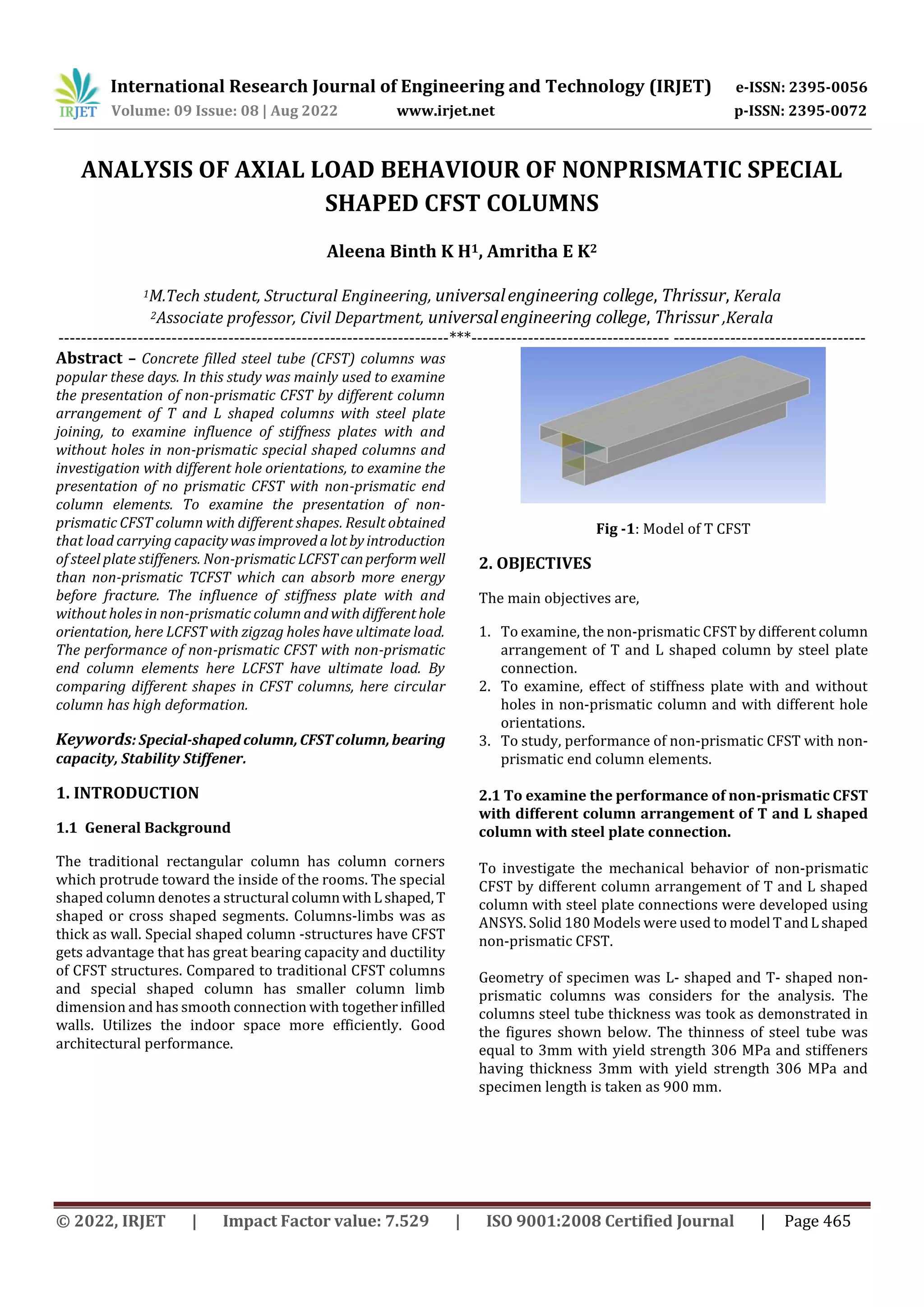
This document analyzes the axial load behavior of non-prismatic concrete filled steel tube (CFST) columns with special shapes through numerical modeling. The study examines T-shaped and L-shaped CFST columns with steel plate connections, the effect of stiffness plates with and without holes, and the performance of non-prismatic CFST with non-prismatic end elements. The results show that load carrying capacity improved with steel plate stiffeners. Non-prismatic LCFST performed better than TCFST by absorbing more energy before fracture. LCFST with zigzag holes had the ultimate load. Circular CFST columns had higher deformation compared to other cross-sections.


