Download as PDF, PPTX


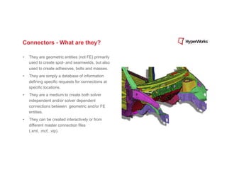
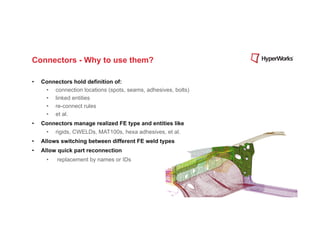
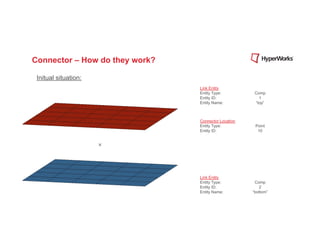
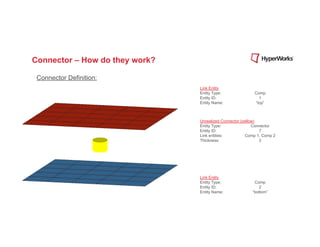
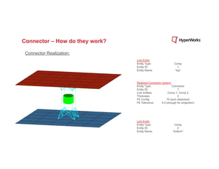
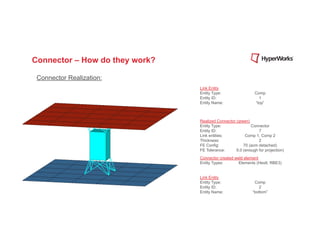
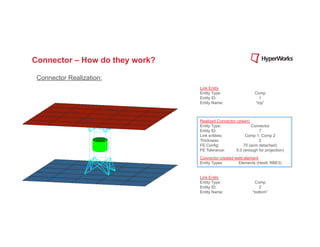
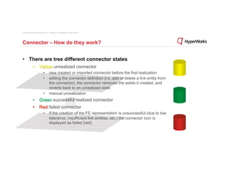
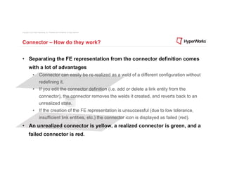
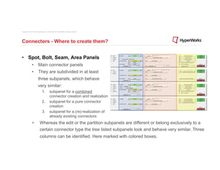
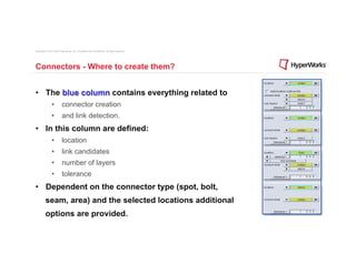
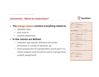
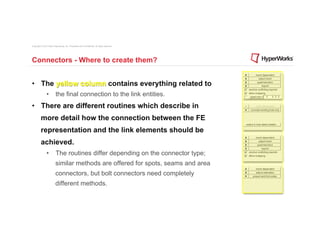
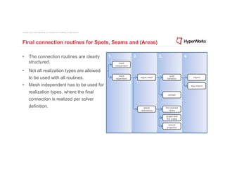
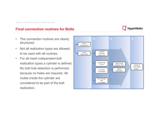
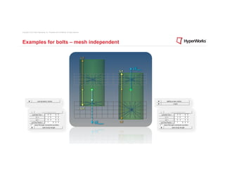


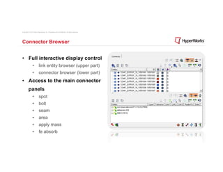


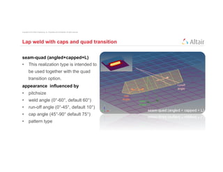
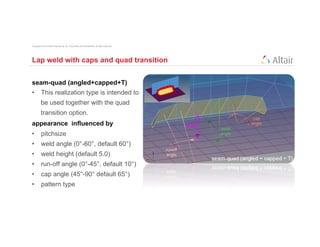


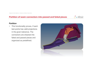

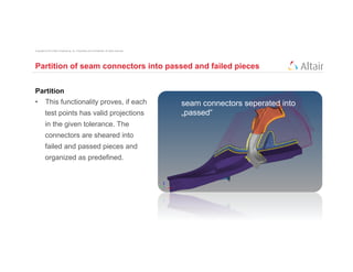
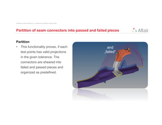
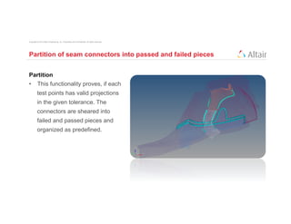
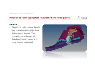


The document discusses connectors in simulation modeling. Connectors define connection locations and linked entities, and manage realized finite element representations like welds. They allow quick reconnection of parts. Connectors have three states - unrealized, realized, and failed. They separate the connection definition from the finite element representation, allowing easy re-realization with different element types. Connector panels are used to create different connector types and control their realization.


![Getting Started with Apache Spark: Big Data Made Simple [Free Meetup]](https://cdn.slidesharecdn.com/ss_thumbnails/apachesparkgettingstarted-260203175547-8361bcc3-thumbnail.jpg?width=640&height=640&fit=bounds)


