Download as PDF, PPTX
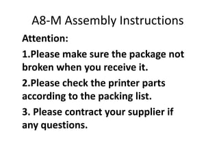
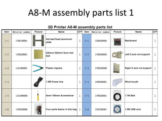
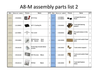
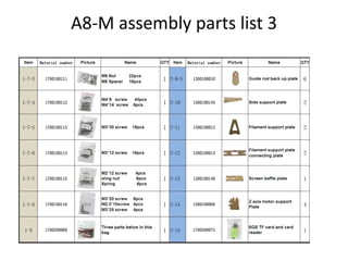
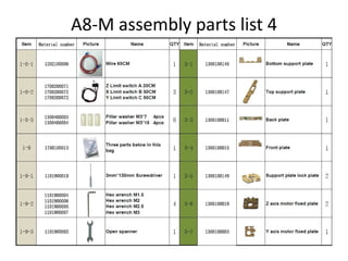
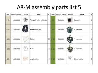
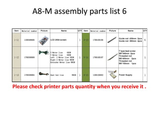
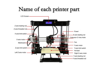
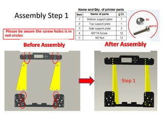
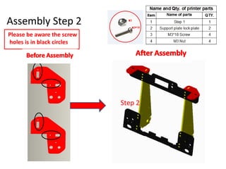
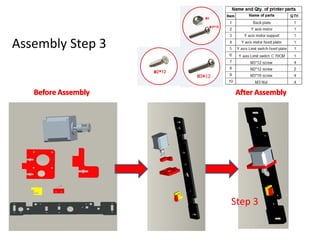
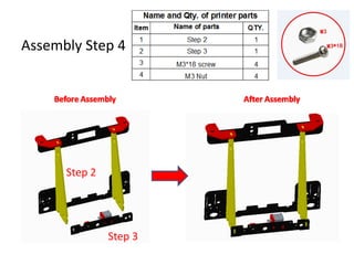
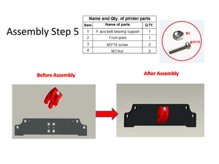
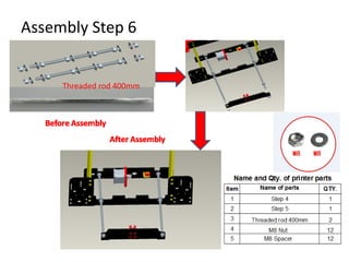
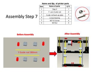
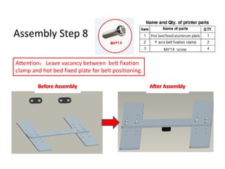
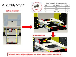
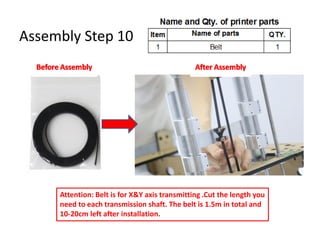
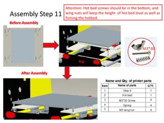
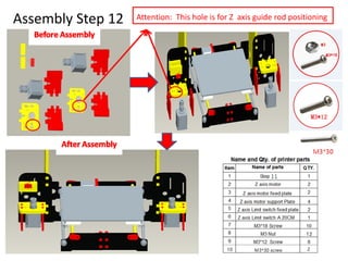
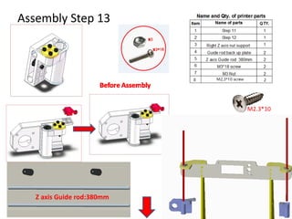
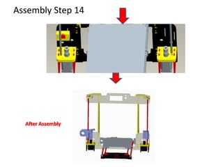
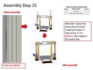
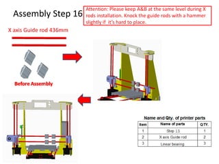
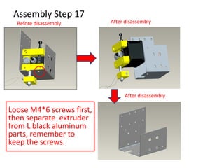
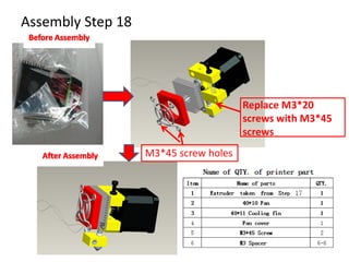
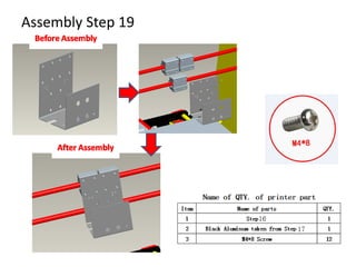
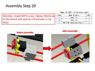
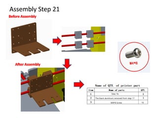
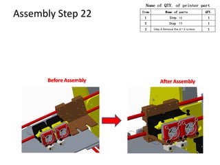
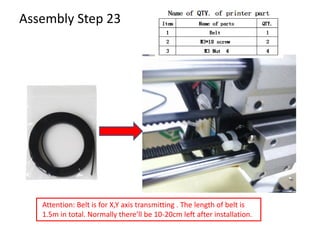
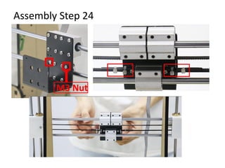
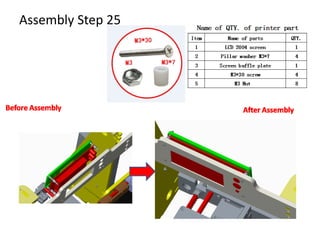
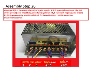
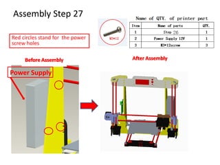
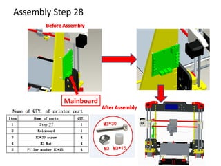
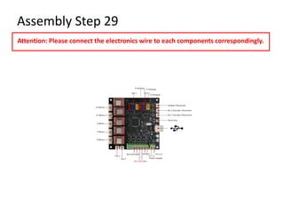
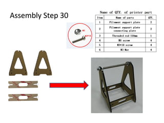

This document provides step-by-step assembly instructions for an A8-M 3D printer. It includes 30 steps to assemble the various components such as the frame, belts, motors, electronics, and includes warnings and attention notes for proper assembly. The assembly requires checking that all parts are included, placing screws and rods in their proper positions, connecting wiring and belts, and calibrating the print bed height.


![english presentation.pptx [Réparé].pptx](https://cdn.slidesharecdn.com/ss_thumbnails/englishpresentation-251208214905-5286d8ce-thumbnail.jpg?width=640&height=640&fit=bounds)


