59 355-9702 rev-1
•
0 likes•173 views

This add-on kit contains various parts to allow for flexible installation of control systems that use an L-shaped heater. The kit includes a rubber motor base, equipment base, bonding wire, screws, washers, pump union, tee, strain reliefs, and optional amp adapter kit and blower. To install, locate the equipment base and place the pump, motor, and heater on it. Attach the motor and secure it with screws and washers. Optional equipment like the blower and control system can also be secured. A bonding wire connects equipment to the control ground. A thermowell tee is glued to the pump union for sensor placement.

Recommended
More Related Content
Similar to 59 355-9702 rev-1
Similar to 59 355-9702 rev-1 (18)
More from Accurate Pool & Spa Services, llc
More from Accurate Pool & Spa Services, llc (20)
59 355-9702 rev-1
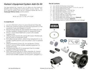
- 1. Horizon’s Equipment System Add-On Kit This kit contains: A. 1ea. 59-270-1010 Rubber Motor Base The idea behind the “Add-On” kit is to allow you the maximum B. 1ea. 59-270-1005 Equipment Base 1”x 15-1/4” x 26-1/4” flexibility when installing the control system of your choice. This C. 1ea. 60-555-3000 Bonding Wire kit is used for systems that use an L-Shaped heater like that of D. 6ea. 59-555-2050 Screw, 1”#10 Self Tap Hydroquip Platinum Series control systems. E. 2ea. 59-555-2051 Washer, 3/16 x 9/16 F. 1ea. 89-270-1166 2” Pump Union Dimensions G. 1ea. 89-270-1442 Tee, 2”Sx2”Spgx1/2”Fpt W-26 1/4” x D- 15 1/4” x H-15 3/4” H. 2ea. 60-555-1225 Strain Relief, 1/2” I. 1ea. 59-322-2000 Amp Adapter Kit 3-pin (Optional) J. 1ea. Blower Various Voltages (Optional) K. 1ea. Pump & Motor of Various Horsepower and Voltages To install this kit: 1. Locate a flat level surface to place Equipment Base (B). 2. There are numerous options for placing equipment on the equipment base see Diagram A and B. 3. Place Pump & Motor (K) with Rubber Motor Base (A) and A B installer supplied L-Shaped Heater on equipment base. 4. Attach 1 each Strain Relief (H) to motor with installer supplied cord. C 5. Utilizing 2 each Screws (D), along with 2 each Washers (E), secure motor to equipment base. 6. If kit utilizes blower option, attach Amp Adapter Kit ( I ) to installer supplied blower cord and attach cord to optional F blower. E 7. Utilizing remaining Screws (D), secure Blower, Control I D System, and any other installer supplied equipment to equipment base. G 8. Install Bonding Wire (C) to equipment then to installer supplied control grounding lug. 9. Glue Thermowell Tee (G) to Union Assembly (F), thread H remaining Strain Relief (H) to Tee Assembly and secure sensor from installer supplied control system. (Diagram C ) J K http://www.MyPoolSpas.com Wholesale Pool and Spa Parts 920-925-3094
- 2. Diagram A Diagram B Equipment System Add-On Kit Instructions Diagram C For Systems With L-Shaped Heaters http://www.MyPoolSpas.com Wholesale Pool and Spa Parts 920-925-3094 Doc#59-355-9702 Rev. 1