Download to read offline
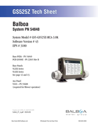
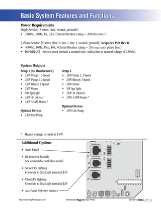
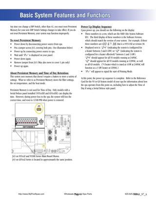
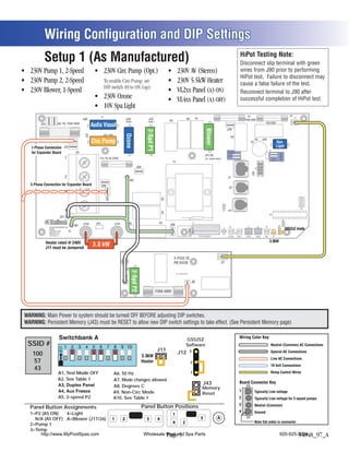
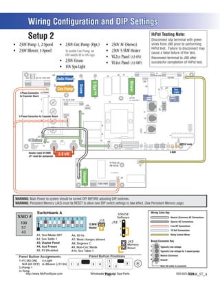
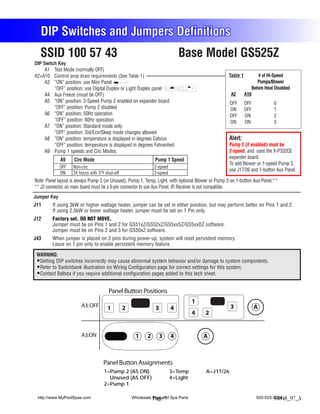
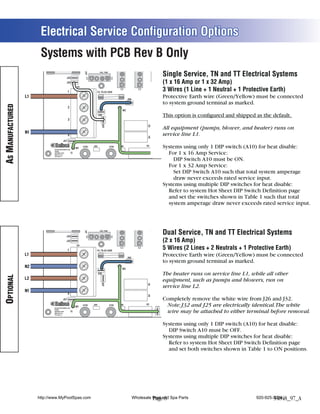
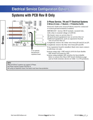
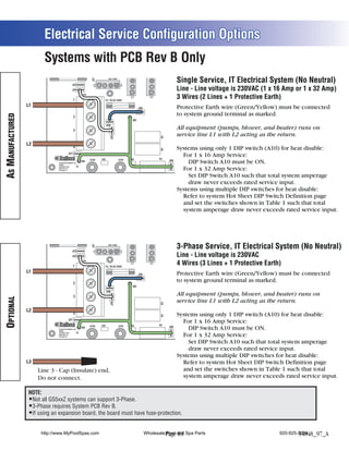

This document provides specifications for the Balboa GS525Z spa control system. Key details include: - The system model is a GS5-GS525Z-RCA-3.0K with software version 43. - It requires a base PCBA and PCB as well as panels for different spa models. - The basic system features include power requirements, outputs, and additional optional devices. - Wiring configurations and DIP switch settings are outlined for setups 1 and 2, showing connections for heaters, pumps, blowers, and other devices.


