Download to read offline


![Operation 5
11
WARNING: The operation of any chipper shredder
can result in foreign objects being thrown into the
eyes, which can damage your eyes severely. Always
wear the safety glasses provided with this unit or
eye shields before chipping or shredding and while
performing any adjustments or repairs.
Starting Engine
IMPORTANT:
units, different starting instructions may apply to your particular
engine. Some engines may have a fuel petcock, some may not.
units will utilize a choke system, while others will require priming.
These factors depend on what make and model engine comes
with your particular unit. For these reasons, please refer to the
Basic Starting Procedure:
1. Attach spark plug wire to spark plug. Make certain the
metal cap on the end of the spark plug is fastened securely
over metal tip on the spark plug.
2.
3.
See Figure 5-1. If the unit has a primer, prime the motor as
NOTE: A warm engine may not require choking or priming.
4. Move throttle control lever to FAST position (if equipped).
See Figure 5-1.
Figure 5-1
5. Grasp starter handle and pull rope out slowly until engine
reaches start of compression cycle (rope will pull slightly
harder at this point).
NOTE: A noise will be heard when finding the start of the
compression cycle. This noise is caused by the flails and
fingers, which are part of the shredding mechanism, and it
should be expected until the impeller reaches full speed.
Pull rope with a rapid, continuous, full arm stroke. Keep a
firm grip on starter handle. Let rope rewind slowly.
Repeat the previous steps until engine starts. When engine
starts, move choke control gradually to RUN position until
the engine is running smoothly.
WARNING: Never run the engine indoors or in a
poorly ventilated area. Engine exhaust contains
carbon monoxide, an odorless and deadly gas.
Stopping Engine
1.
NOTE: See your engine manual packed with your unit for
more detailed instructions.
CAUTION: Never stop the engine by moving the
engine damage could result.
Figure 5-2
Lowering the Hopper
1. With one hand grasp the handle at the top of the hopper
and lift slightly.
2. With the other hand pull out on the release rod and lower
the hopper to the ground.
Operation 5
11
WARNING: The operation of any chipper shredder
can result in foreign objects being thrown into the
eyes, which can damage your eyes severely. Always
wear the safety glasses provided with this unit or
eye shields before chipping or shredding and while
performing any adjustments or repairs.
Starting Engine
IMPORTANT:
units, different starting instructions may apply to your particular
engine. Some engines may have a fuel petcock, some may not.
units will utilize a choke system, while others will require priming.
These factors depend on what make and model engine comes
with your particular unit. For these reasons, please refer to the
Basic Starting Procedure:
1. Attach spark plug wire to spark plug. Make certain the
metal cap on the end of the spark plug is fastened securely
over metal tip on the spark plug.
2.
3.
See Figure 5-1. If the unit has a primer, prime the motor as
NOTE: A warm engine may not require choking or priming.
4. Move throttle control lever to FAST position (if equipped).
See Figure 5-1.
Figure 5-1
5. Grasp starter handle and pull rope out slowly until engine
reaches start of compression cycle (rope will pull slightly
harder at this point).
NOTE: A noise will be heard when finding the start of the
compression cycle. This noise is caused by the flails and
fingers, which are part of the shredding mechanism, and it
should be expected until the impeller reaches full speed.
Pull rope with a rapid, continuous, full arm stroke. Keep a
firm grip on starter handle. Let rope rewind slowly.
Repeat the previous steps until engine starts. When engine
starts, move choke control gradually to RUN position until
the engine is running smoothly.
WARNING: Never run the engine indoors or in a
poorly ventilated area. Engine exhaust contains
carbon monoxide, an odorless and deadly gas.
Stopping Engine
1.
NOTE: See your engine manual packed with your unit for
more detailed instructions.
CAUTION: Never stop the engine by moving the
engine damage could result.
Figure 5-2
Lowering the Hopper
1. With one hand grasp the handle at the top of the hopper
and lift slightly.
2. With the other hand pull out on the release rod and lower
the hopper to the ground.
Operation 5
11
WARNING: The operation of any chipper shredder
can result in foreign objects being thrown into the
eyes, which can damage your eyes severely. Always
wear the safety glasses provided with this unit or
eye shields before chipping or shredding and while
performing any adjustments or repairs.
Starting Engine
IMPORTANT:
units, different starting instructions may apply to your particular
engine. Some engines may have a fuel petcock, some may not.
units will utilize a choke system, while others will require priming.
These factors depend on what make and model engine comes
with your particular unit. For these reasons, please refer to the
Basic Starting Procedure:
1. Attach spark plug wire to spark plug. Make certain the
metal cap on the end of the spark plug is fastened securely
over metal tip on the spark plug.
2.
3.
See Figure 5-1. If the unit has a primer, prime the motor as
NOTE: A warm engine may not require choking or priming.
4. Move throttle control lever to FAST position (if equipped).
See Figure 5-1.
Figure 5-1
5. Grasp starter handle and pull rope out slowly until engine
reaches start of compression cycle (rope will pull slightly
harder at this point).
NOTE: A noise will be heard when finding the start of the
compression cycle. This noise is caused by the flails and
fingers, which are part of the shredding mechanism, and it
should be expected until the impeller reaches full speed.
Pull rope with a rapid, continuous, full arm stroke. Keep a
firm grip on starter handle. Let rope rewind slowly.
Repeat the previous steps until engine starts. When engine
starts, move choke control gradually to RUN position until
the engine is running smoothly.
WARNING: Never run the engine indoors or in a
poorly ventilated area. Engine exhaust contains
carbon monoxide, an odorless and deadly gas.
Stopping Engine
1.
NOTE: See your engine manual packed with your unit for
more detailed instructions.
CAUTION: Never stop the engine by moving the
engine damage could result.
Figure 5-2
Lowering the Hopper
1. With one hand grasp the handle at the top of the hopper
and lift slightly.
2. With the other hand pull out on the release rod and lower
the hopper to the ground.
11
shredder
nto the
Always
nit or
nd while
articular
ay not.
e priming.
comes
to the
the
securely
motor as
priming.
ipped).
engine
ightly
NOTE: A noise will be heard when finding the start of the
compression cycle. This noise is caused by the flails and
fingers, which are part of the shredding mechanism, and it
should be expected until the impeller reaches full speed.
Pull rope with a rapid, continuous, full arm stroke. Keep a
firm grip on starter handle. Let rope rewind slowly.
Repeat the previous steps until engine starts. When engine
starts, move choke control gradually to RUN position until
the engine is running smoothly.
WARNING: Never run the engine indoors or in a
poorly ventilated area. Engine exhaust contains
carbon monoxide, an odorless and deadly gas.
Stopping Engine
1.
NOTE: See your engine manual packed with your unit for
more detailed instructions.
CAUTION: Never stop the engine by moving the
engine damage could result.
Figure 5-2
Lowering the Hopper
1. With one hand grasp the handle at the top of the hopper
and lift slightly.
2. With the other hand pull out on the release rod and lower
the hopper to the ground.
Operation 5
11
WARNING: The operation of any chipper shredder
can result in foreign objects being thrown into the
eyes, which can damage your eyes severely. Always
wear the safety glasses provided with this unit or
eye shields before chipping or shredding and while
performing any adjustments or repairs.
Starting Engine
IMPORTANT:
units, different starting instructions may apply to your particular
engine. Some engines may have a fuel petcock, some may not.
units will utilize a choke system, while others will require priming.
These factors depend on what make and model engine comes
with your particular unit. For these reasons, please refer to the
Basic Starting Procedure:
1. Attach spark plug wire to spark plug. Make certain the
metal cap on the end of the spark plug is fastened securely
over metal tip on the spark plug.
2.
3.
See Figure 5-1. If the unit has a primer, prime the motor as
NOTE: A warm engine may not require choking or priming.
4. Move throttle control lever to FAST position (if equipped).
See Figure 5-1.
Figure 5-1
5. Grasp starter handle and pull rope out slowly until engine
reaches start of compression cycle (rope will pull slightly
harder at this point).
NOTE: A noise will be heard when finding the start of the
compression cycle. This noise is caused by the flails and
fingers, which are part of the shredding mechanism, and it
should be expected until the impeller reaches full speed.
Pull rope with a rapid, continuous, full arm stroke. Keep a
firm grip on starter handle. Let rope rewind slowly.
Repeat the previous steps until engine starts. When engine
starts, move choke control gradually to RUN position until
the engine is running smoothly.
WARNING: Never run the engine indoors or in a
poorly ventilated area. Engine exhaust contains
carbon monoxide, an odorless and deadly gas.
Stopping Engine
1.
NOTE: See your engine manual packed with your unit for
more detailed instructions.
CAUTION: Never stop the engine by moving the
engine damage could result.
Figure 5-2
Lowering the Hopper
1. With one hand grasp the handle at the top of the hopper
and lift slightly.
2. With the other hand pull out on the release rod and lower
the hopper to the ground.
Эксплуатация
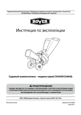
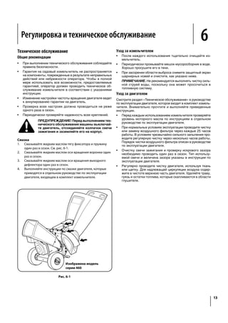
Рис. 5-1
5. Крепко удерживайте рукоятку стартера и медленно тяните
пусковой трос до тех пор, пока двигатель не перейдет в
такт компрессии (с этого момента трос двигается с неко-
торым усилием).
ПРИМЕЧАНИЕ. При переходе в такт компрессии измель-
читель шумит. Этот шум производится шарнирными но-
жами и захватами, которые являются составной частью
измельчающего механизма. Шум не прекратится, пока
крыльчатка не наберет полную скорость.
6. Резко дерните шнур стартера на полный взмах руки. Не
бросайте рукоятку стартера. Медленно отпустите шнур.
7. Повторяйте предыдущие шаги до запуска двигателя. По-
сле запуска двигателя постепенно передвигайте рукоятку
обогатителя в положение «RUN», пока двигатель не станет
работать ровно.
Рис. 5-2
Нижнее положение воронки
1. Одной рукой удерживайте рукоятку на вершине воронки и
немного приподнимите ее.
2. Другой рукой потяните тягу фиксатора и опустите воронку
на землю.
Остановка двигателя
1. Переведите рукоятку управления дроссельной заслонкой
(при ее наличии) в положение «STOP» или установите
тумблер в положение «OFF». См. рис. 5-2.
ПРИМЕЧАНИЕ. Более подробные инструкции вы найдете
в руководстве по эксплуатации двигателя, входящем в
комплект измельчителя.
ВНИМАНИЕ! Запрещается останавливать дви-
гатель путем перевода рукоятки обогатителя в
положение «CHOKE». Это опасно возникнове-
нием обратной вспышки, возгорания или риском
повреждения измельчителя.
ПРЕДУПРЕЖДЕНИЕ! Не запускайте двигатель в
помещении или в плохо проветриваемых местах.
Выхлопные газы содержат ядовитую окись угле-
рода — газ без цвета и запаха.
Запуск двигателя
ВАЖНО. Поскольку настоящее руководство предназначается
для нескольких различных моделей, к вашему конкретному
двигателю могут применяться различные инструкции по за-
пуску. Некоторые двигатели оборудованы топливным краном,
другие - нет. Некоторые двигатели оборудованы выключате-
лем, другие - нет. В некоторых машинах используется систе-
ма холодного запуска, тогда как другим требуется подкачка
топлива. Эти факторы зависят от марки и модели двигателя,
установленного в вашем измельчителе. По этим причинам
выполняйте инструкции руководства по эксплуатации для
правильной последовательности запуска.
Основной порядок запуска
1. Установите высоковольтный провод свечи зажигания на
свечу. Убедитесь в том, что металлический колпачок на
конце свечи зажигания плотно соприкасается с металли-
ческим наконечником на свече.
2. Откройте клапан подачи топлива (при его наличии) и убе-
дитесь в том, что выключатель (при наличии) установлен
в положение «On».
3. При наличии системы холодного запуска пере-
ведите ее рукоятку в положение «CHOKE» [Обо-
гатитель]. См. рис. 5-1. Если измельчитель
оборудован насосом подкачки, подкачайте топливо в дви-
гатель согласно указаниям руководства по эксплуатации.
ПРИМЕЧАНИЕ. При запуске теплого двигателя обогаще-
ние и подкачка могут не потребоваться.
4. При наличии рукоятки управления дроссельной заслонкой
переведите ее в положение «FAST». См. рис. 5-1.
ПРЕДУПРЕЖДЕНИЕ! Мелкие посторонние пред-
меты, которые разлетаются во все стороны от
работающего садового измельчителя, могут вы-
звать серьезную травму при попадании в глаз.
При работе с измельчителем, а также при вы-
полнении любых регулировок или ремонта всегда
надевайте защитные очки (входят в комплект)
или щиток.
Operation 5
WARNING: The operation of any chipper shredder
can result in foreign objects being thrown into the
eyes, which can damage your eyes severely. Always
wear the safety glasses provided with this unit or
eye shields before chipping or shredding and while
performing any adjustments or repairs.
Starting Engine
IMPORTANT:
units, different starting instructions may apply to your particular
engine. Some engines may have a fuel petcock, some may not.
units will utilize a choke system, while others will require priming.
These factors depend on what make and model engine comes
with your particular unit. For these reasons, please refer to the
Basic Starting Procedure:
1. Attach spark plug wire to spark plug. Make certain the
metal cap on the end of the spark plug is fastened securely
over metal tip on the spark plug.
2.
3.
See Figure 5-1. If the unit has a primer, prime the motor as
NOTE: A warm engine may not require choking or priming.
4. Move throttle control lever to FAST position (if equipped).
See Figure 5-1.
NOTE: A noise will be heard when finding the start of the
compression cycle. This noise is caused by the flails and
fingers, which are part of the shredding mechanism, and it
should be expected until the impeller reaches full speed.
Pull rope with a rapid, continuous, full arm stroke. Keep a
firm grip on starter handle. Let rope rewind slowly.
Repeat the previous steps until engine starts. When engine
starts, move choke control gradually to RUN position until
the engine is running smoothly.
WARNING: Never run the engine indoors or in a
poorly ventilated area. Engine exhaust contains
carbon monoxide, an odorless and deadly gas.
Stopping Engine
1.
NOTE: See your engine manual packed with your unit for
more detailed instructions.
CAUTION: Never stop the engine by moving the
engine damage could result.
Figure 5-2
Lowering the Hopper
1. With one hand grasp the handle at the top of the hopper](https://image.slidesharecdn.com/371ab147b49a90522bdf2cbfeb3bfe881-150503012841-conversion-gate02/85/MTD-Rover-464-Q-11-320.jpg)

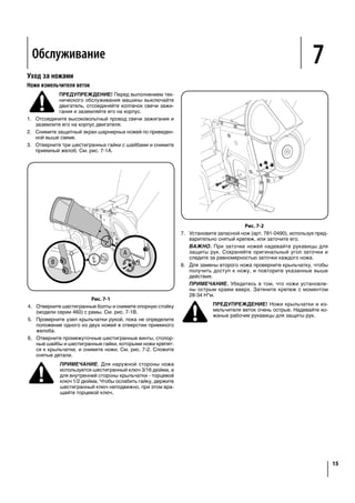

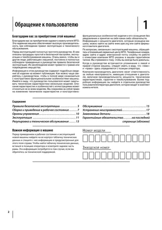
![Неисправность Вероятная причина Способ устранения
Двигатель не запускается 1. Рукоятка дроссельной заслонки не зани-
мает правильное положение для запуска.
2. Отсоединен высоковольтный провод свечи
зажигания.
3. Рукоятка обогатителя находится не в по-
ложении «CHOKE» [Обогатитель] (при на-
личии соответствующей системы).
4. Топливный бак пуст или заправлено не-
свежее топливо.
5. Не произведена подкачка топлива (если
двигатель имеет систему подкачки).
6. Загрязнена или повреждена свеча зажи-
гания.
7. Засорен топливопровод.
8. В топливо попала вода
1. Переведите рукоятку управления дрос-
сельной заслонкой в положение «FAST»
или «START».
2. Подсоедините высоковольтный провод к
свече зажигания.
3. Переведите рукоятку обогатителя в по-
ложение «CHOKE».
4. Заправьте в бак чистое и свежее топливо.
5. Включите подкачку топлива, как описано
в руководстве по эксплуатации двигателя.
6. Очистите, отрегулируйте зазор или заме-
ните.
7. Прочистите топливопровод.
8. Подождите несколько минут и попробуйте
запустить снова, но не используйте под-
качку
Двигатель работает
нестабильно
1. Ослабло крепление колпачка свечи за-
жигания.
2. Машина работает с включенным обогати-
телем (если он имеется).
3. Засорен топливопровод или заправлено
несвежее топливо.
4. Низкие обороты двигателя.
5. В топливную систему попала вода или
грязь.
6. Загрязнен воздушный фильтр.
7. Карбюратор не отрегулирован
1. Подсоедините колпачок свечи зажигания
и закрепите контакт.
2. Переведите рукоятку обогатителя в по-
ложение «OFF».
3. Очистите топливопровод; залейте в бак
свежее топливо.
4. Всегда эксплуатируйте двигатель с полно-
стью открытой дроссельной заслонкой.
5. Слейте топливо из бака. Заполните бак
свежим топливом.
6. Смотрите руководство по эксплуатации
двигателя.
7. Обратитесь в авторизованный сервисный
центр
Двигатель перегревается 1. Недостаточный уровень моторного масла.
2. Загрязнен воздушный фильтр.
3. Карбюратор отрегулирован неправильно
1. Заправьте картер подходящим маслом.
2. Смотрите руководство по эксплуатации
двигателя.
3. Обратитесь в авторизованный сервисный
центр
На высоких оборотах
двигатель работает
неравномерно
1. Мал искровой промежуток свечи.
2. Неправильная регулировка карбюратора
для холостого хода
1. Извлеките свечу зажигания и отрегулируй-
те ее зазор до величины 0,76 мм.
2. Обратитесь в авторизованный сервисный
центр
Слишком сильная
вибрация
1. Неплотная затяжка деталей или повреж-
дение крыльчатки
2. Обратитесь в авторизованный сервисный
центр
Измельчитель не выбра-
сывает переработанный
материал
1. Засорение области выброса.
2. Посторонний предмет заклинил крыльчат-
ку.
3. Низкие обороты двигателя
1. Немедленно заглушите двигатель и от-
соедините высоковольтный провод свечи
зажигания. Очистите защитный экран и
внутреннюю часть выпускного желоба.
2. Заглушите двигатель и отсоедините высо-
ковольтный провод свечи зажигания. Уда-
лите посторонний объект из крыльчатки.
3. Всегда эксплуатируйте двигатель с полно-
стью открытой дроссельной заслонкой
Скорость выброса зна-
чительно уменьшилась
или изменилась степень
измельчения
1. Низкие обороты двигателя.
2. Затупились ножи измельчителя
1. Всегда эксплуатируйте двигатель с полно-
стью открытой дроссельной заслонкой.
2. Замените ножи измельчителя или обрати-
тесь в авторизованный сервисный центр
Troubleshooting 8
17
Problem Cause Remedy
Engine Fails to start 1. Throttle lever not in correct starting position.
2. Spark plug wire disconnected.
3.
4. Fuel tank empty or stale fuel.
5. Engine not primed (if equipped).
Faulty spark plug.
8. Engine flooded.
1. Move throttle lever to FAST or START
position.
2. Connect wire to spark plug.
3.
4. Fill tank with clean, fresh gasoline.
5. Prime engine as instructed in Engine Manual.
Clean, adjust gap, or replace.
Clean fuel line.
8. Wait a few minutes to restart, but do not
prime.
Engine runs erratic 1. Spark plug boot loose.
2.
3.
4. Low engine RPM.
5. Water or dirt in fuel system.
Dirty air cleaner.
Carburetor out of adjustment.
1. Connect and tighten spark plug boot.
2.
3. Clean fuel line; fill tank with clean, fresh
gasoline.
4. Always run engine at full throttle.
5. Drain fuel tank. Refill with fresh fuel.
Refer to engine manual.
See authorized service dealer.
Engine overheats 1. Engine oil level low.
2. Dirty air cleaner.
3. Carburetor not adjusted properly.
1. Fill crankcase with proper oil.
2. Refer to engine manual.
3. See authorized service dealer.
(hesitates) at
high speed
1. Spark plug gap too close.
2. Carburetor idle mixture adjustment
improperly set.
1. Remove spark plug and adjust gap to .030”.
2. See authorized service dealer.
Excessive Vibration 1. Loose parts or damaged impeller. 2. See authorized service dealer.
Unit does not discharge 1. Discharge area clogged.
2. Foreign object lodged in impeller.
3. Low engine RPM.
1. Stop engine immediately and disconnect
spark plug wire. Clean flail screen and inside
of discharge opening.
2. Stop engine and disconnect spark plug wire.
Remove lodged object.
3. Always run engine at full throttle.
Rate of discharge slows
considerably or composition
of discharged material
changes
1. Low engine RPM.
2. Chipper blade dull.
1. Always run engine at full throttle.
2. Replace chipper blade or see your authorized
service dealer.
Устранение неисправностей](https://image.slidesharecdn.com/371ab147b49a90522bdf2cbfeb3bfe881-150503012841-conversion-gate02/85/MTD-Rover-464-Q-17-320.jpg)


Руководство по эксплуатации садового измельчителя MTD включает важные правила безопасной эксплуатации, инструкции по сборке и обслуживанию, а также информацию по устранению неисправностей. Перед использованием машины пользователям рекомендуется внимательно ознакомиться с руководством и соблюдать все предостережения, чтобы избежать травм. Указано, что игнорирование инструкций может привести к серьезным травмам или повреждению имущества.


![71071733[1]](https://cdn.slidesharecdn.com/ss_thumbnails/710717331-140314061848-phpapp01-thumbnail.jpg?width=640&height=640&fit=bounds)


