1. 2 | Technical Information Rev 1 Contact Applications Engineering at: 800-233-1722
A bolted joint is an assembly that relies on each component to work properly. The perfor-
mance and success of the bolted joint depends on the quality and design of each of these
components. There are three major components of every bolted joint:
1. Flanges (Flange design / Groove dimensions & finish)
2. Bolts / Fasteners
3. Seal / Gasket
The above components cannot be designed mutually exclusive of each other. They must
be considered together as a system during the design process. If any part of the bolted
joint assembly does not perform properly, the joint as a whole will not perform to expec-
tations and may leak.
Bolted Joints
Bolt Load and Tightening Torque
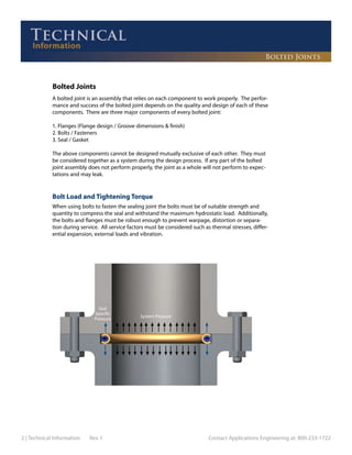
When using bolts to fasten the sealing joint the bolts must be of suitable strength and
quantity to compress the seal and withstand the maximum hydrostatic load. Additionally,
the bolts and flanges must be robust enough to prevent warpage, distortion or separa-
tion during service. All service factors must be considered such as thermal stresses, differ-
ential expansion, external loads and vibration.
System Pressure
Seal
Specific
Pressure
Bolted Joints
2. Contact Applications Engineering at: 800-233-1722 Rev 1 Technical Information | 3
Bolted Joints
Bolt Load Estimates
The following equations may be used to estimate required bolt loads.
NOTE: These estimates are offered as guidelines only. There are many other factors that the flange designer must consider
such as: thermal cycling, vibration, cyclic fatigue, flange thickness, flange rotation, bolt stress relaxation, additional bolt
preload, externally applied loads, etc. The customer is responsible for the flange design and for ensuring that the flanges,
bolts and bolt loads are sufficient for the application. Please refer to Section VIII of the ASME Boiler and Pressure Vessel Code
for code requirements.
Total Bolt Load ≥ Seal Seating Load + Hydrostatic Load + Safety Factor
Seal Seating Load
Total load required to compress the seal to optimal level. This information can be found for each
seal type in the Performance Data sections of the catalog. It is referenced as Y2
and is given in
pounds per circumferential inch (PCI).
Seal Seating Load = Seal Diameter x π x Y2
Hydrostatic Load
Load required to contain the system pressure.
Hydrostatic Load = Maximum system pressure x (π/4) x (Seal Diameter)2
Safety Factor
This is a customer determined safety factor and must consider: system temperature effects, tem-
perature cycling/spikes, pressure cycling/spikes, vibration, etc.
NOTE: A more detailed calculation is available for the Helicoflex spring energized seals. Please see the Helicoflex Seal product
section.
Example Calculation
Seal:
O-Flex metal o-ring, Material = SS321
OD = 4.000in, CS = .125in, wall thickness = .020in
Y2
= 1142 lbs/in
Operating Conditions:
Pressure: 500 psi, Temperature: 70 F
Seating Load = 4.000in x π x 1142lbs/in = 14351 lbs
Hydrostatic Load = 500 lbs/in2
x (π/4) x (4.000in)2
= 6283 lbs
Total Bolt Load Estimate ≥ 14351 lbs + 6283 lbs + customer safety factor
NOTE: each application should be reviewed to determine if additional bolt preload may be required for proper bolt stretch.
3. 4 | Technical Information Rev 1 Contact Applications Engineering at: 800-233-1722
Tightening Torque and Bolt Tension
The following equation may be used to create a rough estimate of the required torque:
T = K x P x D
Where: T= tightening torque (in-lbs)
K*= dynamic coefficient of friction (i.e. minimum = .15 (dry-zinc plated))
P= total bolt load / number of bolts (lbf)
D= nominal bolt diameter (in)
(* Also referred to as the“nut factor”in some texts.)
It must be understood that every bolted joint is unique and the tightening torque should be
determined for each application through experimentation. A properly tightened bolt is one that
is stretched, thus acting like a very rigid spring pulling the mating surfaces together. As the bolt is
tightened it begins to stretch and goes into a state of tension. There are many factors that affect
how much tension occurs when a given amount of tightening torque is applied. These factors in-
clude bolt diameter, bolt grade (strength), and friction. Torque calculations can have significant er-
rors based on these factors, especially friction. Best practice indicates that bolts should be properly
lubricated and hardened washers used under the head and nut.
Where possible, it is recommended the fastener elongation, or stretch, be measured directly to
ensure proper tension or preload, in the fastener.
NOTE: These estimates are offered as guidelines only. There are many other factors that the flange designer must consider
such as: thermal cycling, vibration, cyclic fatigue, flange thickness, flange rotation, bolt stress relaxation, additional bolt
preload, externally applied loads, etc. The customer is responsible for the flange design and for ensuring that the flanges,
bolts and bolt loads are sufficient for the application. Please refer to Section VIII of the ASME Boiler and Pressure Vessel Code
for code requirements.
Bolted Joints