Rangkuman dokumen ini memberikan informasi tentang rancang bangun sistem KERS (Kinetic Energy Recovery System) yang diterapkan pada sepeda motor dengan transmisi rantai dan roda gigi. Sistem ini dirancang untuk dapat memanfaatkan energi pengereman sepeda motor untuk menyimpan energi kinetik pada flywheel, dan menghasilkan daya sebesar 0,153 Hp. Komponen-komponen sistem seperti v-Belt, pulley, roda gigi, pasak, dan bearing tel
Uji Kemampuan Rancangan Sistem Kemudi, Transmisi, dan Pengereman pada Mobil L...Meda Aji Saputro
Penelitian ini bertujuan melakukan rancangan beserta uji performasi
sistem transmisi, sistem kemudi dan sistem pengereman mobil listrik
“Ababil”. Asumsi dasar mobil listrik dirancang adalah tipe protottype
(Mobil beroda tiga, depan dua roda dan belakang satu roda) yang
disesuakan pada regulasi Kontes Mobil Hemat Energi (KMHE) yang
diselenggarakan oleh pemerintah Indonesia melalui Kemenristekdikti.
Panjang wheel base 1,8 m, jarak antar roda depan 0,80 m tinggi
ground clearance 10 cm dan berat total mobil maksimum 108 kg.
Motor listrik yang digunakan adalah tipe BLDC dengan spesifikasi
daya 350 watt, 48 volt dan putaran 470 rpm dengan baterry Li-Ion
berkapasitas 48 V/DC 20 AH. Rancangan sistem transmisi menggunakan sprocket chain, sistem kemudi menggunakan dua tie rod, lengan
tie rod, dan ball joint, sedangkan pengereman menggunakan sistem
cakram hidrolik. Dari hasil pengujian diperoleh hasil mobil yang
mampu bergerak stabil saat melaju di trek lurus maupun belok.
Kecepatan maksimum 50 km/jam. Untuk sistem kemudi, radius belok
minimal 3 meter dengan sudut belokan roda depan 34º, radius belok
maksimal sebesar 6 m dengan belok roda depan 17º. Besarnya gaya
pengereman yang dibutuhkan pada pada jalan datar adalah sebesar
594,57 Newton.
4 Speed Gear box design spur gear with C 6 inch and pitch 5 inchAushafNurIlham
Important, this document may content some miss calculation for the reverse gear, because my final document is gone, this is just the back up.
download here :
https://drive.google.com/drive/folders/1p_VCyaALE2upfF7VxC1iLQgwWIH0UqEL?usp=sharing
Language : Indonesia (IDN : Bahasa)
Copyright : Institue Technology Adhi Tama Surabaya
Open license
Basic 4 speed gearbox with center dimension for the shaft are both 6 inch and contact angle pitch are 5 inch
Spesification
Input 6000 RPM
Max power 104 HP
Speed Gearbox with Ratio:
1st Gear (Input Shaft) - 2nd gear (Counter shaft) 1,2 RcV
3rd Gear (Counter Shaft) - 4th gear (output shaft) 2,5 RV
5th Gear (Counter Shaft) - 6th gear (output shaft) 1,25 RV
7th Gear (Counter Shaft) - 8th gear (output shaft) 1 RV
9th Gear (Counter Shaft) - 10th Gear (Reverse counter) - 11th gear (Counter Shaft) 1,67
for other technical issue you can read it
main reference
Machine Design: Theory and Practice by Aaron D. Deutschman 1975, version 2
Optimasi desain gating system dan riser...._Quantum Teknika_April 2022.pdfVENDITIASYUDHA1
The growth of the automotive industry has made the market demand for motor vehicle spare
parts soar, especially motorcycles, including the demand for cylinder blocks. Procedure of
this research was carried out to analyze the product of 4 stroke motor cylinder block castings,
which include; manufacture of casting product designs, manufacture of gating systems and
riser systems. Results and Discussion based on the results of the shrinkage simulation test
that has been carried out through the type of sand casting casting with the casting material,
namely FCD-600-3 cast iron (1290
o
C) and the impression material used is silica sand (20
o
C)
with a gravity casting type of casting, it can be concluded that the results of design testing 1
(one) obtained a filling velocity of 1.111 m/s, with a filling time of 3.8 seconds and a required
solidification time of 6 minutes. In design 1 (one) there is a shrinkage defect due to shrinkage
located on the sprue and riser of 0.336%. While the test results from design 2 (two) obtained
a filling velocity of 1.09 m/s, with a filling time of 3.9 seconds and a required solidification
time of 5 minutes. In design 2 (two) there is a shrinkage defect due to shrinkage located on
the riser and in the cast product of 0.404%. The conclusion of the test results on both designs,
it was found that design 1 (one) is the most optimal design for cylinder block casting
planning.
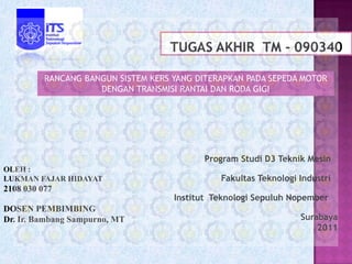
1. RANCANG BANGUN SISTEM KERS YANG DITERAPKAN PADA SEPEDA MOTOR
DENGAN TRANSMISI RANTAI DAN RODA GIGI
Program Studi D3 Teknik Mesin
OLEH :
LUKMAN FAJAR HIDAYAT Fakultas Teknologi Industri
2108 030 077
Institut Teknologi Sepuluh Nopember
DOSEN PEMBIMBING
Dr. Ir. Bambang Sampurno, MT Surabaya
2011
2. Perkembangan teknologi otomotif yang semakin
maju, menuntut kita untuk berlomba menghemat
energi.
Teknologi KERS juga diterapkan pada sepeda di salah
satu universitas di Singapura (Chenghan, 2008).
Widodo, Dedi S, (2010) dan Wibowo (2010), telah
menghasilkan prototipe transmisi KERS pada
kendaraan NOUVO. Namun sistem kerjanya tidak
benar-benar memanfaatkan energi pengereman.
3. Bagaimana merancang
sistem KERS full mekanik
yang diterapkan pada
sepeda motor dengan
transmisi rantai dan roda
gigi, meliputi :
Bagaimana memilih
komponen Bagaimana merakit
sistem KERS
4. Mendapatkan Terciptanya
hasil rancangan prototipe sistem
KERS full mekanik
yang sesuai dan yang dapat
aman sistem diterapkan pada
KERS Sepeda motor
dengan transmisi
rantai dan roda gigi.
5. Dapat memberi Hasil yang
memperoleh
masukan bagi diperoleh dari
teknologi KERS
dunia industry penelitian ini
yang dapat
otomotif dalam dapat membantu
diterapkan pada
bidang desain masyarakat dalam
sepeda motor
perancangan mengetahui dan
dengan transmisi
teknologi KERS menganalisis
rantai dan roda
untuk kendaraan prinsip kerja dari
gigi,
roda dua. sistem KERS.
6. Kendaraan yang dipakai sepeda motor suzuki RC
110cc.
Topik yang dibahas hanya segi transmisi.
Pemilihan komponen diutamakan yang berada
dipasaran.
Tidak membahas jenis material yang digunakan.
Tidak membahas kontruksi.
10. BELT Dan PULLEY
Panjang Belt 50 in
Diameter pulley 2 = 6 in
Jarak dari Pulley = 18,1 in
Dimeter pulley 1 = 2,7 in
11. Roda gigi
Diameter roda gigi
penggerak 4,9 in
Dimeter roda gigi yang
digerakkan 1,14 in
Rasio kecepatan = 4,2
12.
13. Pasak
Jenis Square
W : 0,2 in
H : 0,2 in
Panjang minimum pasak 0,7
in
Bahan pasak AISI 5150 dengan
kekuatan ijin tarik 250 ksi
14. Bearing
D : 40 mm
d : 20 mm
v : 1
b : 3 untuk single
groove deep bearing
15. Energi yang tersimpan
dari flywheel adalah Daya yang dihasilkan
56,98 joule = 0,058Kj, flywheel adalah 0,153
pada 571,56 rpm roda, Hp
dengan daya mesin 7,2 hp
16. Secara keseluruhan semua sistem
berjalan sesuai rancangan awal.
Daya yang tersimpan pada flywheel
sebesar 0,153 hp, Energi Kinetik yang
dihasilkan flywheel sebesar 56,98 joule
Dari hasil perhitungan v-Belt, pulley,
roda gigi, pasak, dan bearing sudah
sesuai perencanaan.