202 607 44 batedor dpz
•
0 likes•195 views

Batedor de ponte rolante caracteristicas tecnicas

Recommended
More Related Content
What's hot
What's hot (20)
Similar to 202 607 44 batedor dpz
Similar to 202 607 44 batedor dpz (20)
Recently uploaded
Recently uploaded (20)
202 607 44 batedor dpz
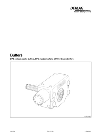
- 1. 1 Buffers DPZ cellular plastic buffers, DPG rubber buffers, DPH hydraulic buffers 1097 EN 202 607 44 714 IS 883 41492144.eps
- 2. 2 Buffers Buffers with a high energy absorption capacity are required to prevent any critical deformation in structural steelwork resulting from travel units colliding with each other or with the end of a track. This type of buffer is used in crane construction and wherever impact energy of a pre- defined maximum force has to be absorbed. The complete volume of the buffer is utilized as pressure is distributed over the whole section of the buffer. Lateral deformation remains low even under maximum com- pression. The favourable diameter-to-length ratio of the buffer ensures that any displacement of the buffers due to play in the guidance of the crane on the rails has no adverse effect. DPZ cellular plastic buffers Due to its excellent physical qualities as regards elasticity, cushioning and energy absorption, the cellular Polyurethane® material is particularly well suited for buffers. The energy absorbed by cellular plastic buffers increases with the speed of impact. This results from the polytropic compression of the gases in the cellular structure. The material is chemically resistant to ozone, oxygen, water, petrol and most oils and industrial greases. The buffer is fully functional at operating temperatures of – 20 °C to + 80 °C. In condi- tions of high humidity in conjunction with high temperatures, the rubber buffer should be used. DPG rubber buffers The buffer consists of a compact elastic rubber. This material features different char- acteristics to that of the cellular plastic buffers. The energy and final force curves for rubber buffers apply to both static and dynamic loads. This buffer material should preferably be used under conditions of high humidity. The buffer is fully functional at operating temperatures of – 30 °C to + 70 °C. DPH hydraulic buffers The buffer is an enclosed system consisting of maintenance free hydraulic elements. Owing to almost uniform deceleration, this buffer makes it possible to achieve the smallest possible braking force for the shortest possible brake path. Sizes DPH 7 and DPH 350 are self-adjusting hydraulic buffers. DPH 25 and DPH 80 are adjustable buffers and may be adjusted by means of a ring for various damping applications (depending on mass or speed). The piston is automatically returned. The permissible ambient operating temperatures range from – 12 °C to + 90 °C for adjustable and to + 65 °C for self-adjusting buffers; using special seals and special oil from – 40 °C to + 120 °C. The maximum axial deviation of the impact direction from the piston rod axis is ap- prox. 3°. Hydraulic buffers can be installed in any position. With the standard mounting arrangement using the adapter, threaded pin and set nut, the hydraulic buffer has the same mounting dimensions as the cellular plastic and rubber buffers and may thus be used to replace them at a later date in already exist- ing installations. Mounting variant II as illustrated in foot or neck mounting configuration is a space- saving arrangement which may be implemented if it is possible to accommodate a larger bore hole. In this case, a second nut is then required for the self-adjusting hy- draulic buffers. 41826044.eps Mannesmann Dematic AG P.O. Box 67, D-58286 Wetter Telephone (+49 2335) 92-0, Telefax (+49 2335) 927676 Internet http://www.dematic.com Manufacturer Type DPZ End face with knobbed surface Set nut Threaded pin Buffer with base plate Diagram shows cellular plastic buffer
- 3. 3 Design and installation information DPZ cellular plastic buffer with internal screw thread suitable for RS wheel blocks and KTL travel units as well as RAM/RN wheel sets Set nut Threaded pin with hexagon socket DPG rubber buffer with internal screw thread suitable for RS wheel blocks and KTL travel units as well as RAM/RN wheel sets Set nut Threaded pin with hexagon socket ¹) Part no. includes cellular plastic buffer, threaded pin and set nut ¹) Part no. includes rubber buffer, threaded pin and set nut 40123644.eps 1 d 3 d 2 d 3 l 1 l M 2 l 3 d 2 d 1 l 3 l 1 d M 2 l 41122444.eps e z i S t h g i e W ) ¹ . o n t r a P 1 d 2 d 3 d 1 l 2 l 3 l M ] g k [ 0 7 Z P D 0 7 5 6 2 1 M 6 6 0 4 5 2 2 1 M 5 3 , 0 4 4 2 2 5 1 1 8 0 0 1 Z P D 0 0 1 5 9 0 0 1 5 4 0 3 3 7 , 0 4 4 3 2 5 1 1 8 0 3 1 Z P D 0 3 1 2 2 1 0 2 1 5 5 0 3 1 1 , 1 4 4 4 2 5 1 1 8 0 6 1 Z P D 0 6 1 5 5 1 0 5 1 5 5 0 4 7 , 1 4 4 8 9 0 1 1 8 0 1 2 Z P D 0 1 2 0 0 2 0 2 M 0 0 2 5 8 8 6 0 2 M 0 , 4 4 4 9 9 0 1 1 8 e z i S t h g i e W ) ¹ . o n t r a P 1 d 2 d 3 d 1 l 2 l 3 l M ] g k [ 3 6 G P D 3 6 6 5 2 1 M 7 6 0 4 7 , 3 1 2 1 M 2 3 , 0 4 4 6 1 0 1 1 8 0 8 G P D 0 8 1 7 4 8 5 4 7 , 3 1 9 5 , 0 4 4 7 1 0 1 1 8 0 0 1 G P D 0 0 1 0 9 5 0 1 5 5 7 , 3 1 3 1 , 1 4 4 8 1 0 1 1 8 0 6 1 G P D 0 6 1 1 5 1 1 3 1 5 5 7 , 3 1 4 , 4 4 4 6 6 0 1 1 8 0 0 2 G P D 0 0 2 9 8 1 0 2 M 6 6 1 5 8 0 2 0 2 M 4 , 8 4 4 7 6 0 1 1 8
- 4. 4 DPH hydraulic buffer Standard mounting variant with adapter, threaded pin and set nut suitable for RS wheel blocks and KTL travel units as well as RAM/RN wheel sets Mounting variant II Foot or neck mounting config. 41546802.eps 41546801.eps Standard mounting variant with adapter ¹) Part no. includes hydraulic buffer, nut, adapter, threaded pin and set nut ²) Second nut required for mounting variant II with foot or neck mounting configuration e z i S y g r e n E e v i t c e f f E r e f f u b c i l u a r d y H r e t p a d A n i P ) ¹ . o n t r a P n o i t p r o s b a s s a m e k o r t S h t g n e L d a e r h T t h g i e W E u p m u p H 1 l 3 d 3 l 2 d M l 2 l ] m N [ ] g k [ ] g k [ 7 H P D f l e s g n i t s u j d a 8 6 3 1 1 + 0 3 1 1 4 , 5 2 9 , 9 4 1 ) ² 5 , 1 x 5 2 M 2 0 1 3 2 6 2 , 0 2 1 M 7 6 1 0 4 4 4 4 9 2 1 1 8 5 2 H P D e l b a t s u j d a 0 3 2 0 0 5 + 0 0 0 0 8 8 , 0 5 9 8 1 F N U 2 1 - ¼ 1 7 1 4 , 5 2 6 7 , 0 2 1 M 7 0 2 0 4 4 4 5 9 2 1 1 8 0 8 H P D e l b a t s u j d a 0 8 7 4 5 + 0 0 5 9 6 7 6 4 2 F N U 2 1 - ¾ 1 3 2 8 3 1 , 2 2 1 M 7 6 2 0 4 4 4 6 9 2 1 1 8 0 5 3 H P D f l e s g n i t s u j d a 0 9 3 3 0 6 3 1 + 0 0 8 6 2 5 1 0 5 4 4) 2 x 4 6 M 8 3 0 6 7 , 4 0 2 M 8 7 4 0 4 N 4 4 7 9 2 1 1 8
- 5. 5 Cellular plastic buffer Flexibility range s [mm] Energy Epu [Nm] Buffer final forces Fpu [kN] Cellular plastic buffer Flexibility range s [mm] Energy Epu [Nm] Buffer final forces Fpu [kN] Cellular plastic buffer Flexibility range s [mm] Energy Epu [Nm] Buffer final forces Fpu [kN] Diagram 1 DPZ 70 cellular plastic buffer Diagram 2 DPZ 100 cellular plastic buffer Diagram 3 DPZ 130 cellular plastic buffer 10 v = 60 m/min v = 120 m/min v = 120 m/min v = 60 m/min 20 30 40 50 600 400 200 200 5 10 15 20 41122544.eps 10 v = 60 m/min v = 120 m/min v = 120 m/min v = 60 m/min 20 30 40 50 60 70 80 200 400 600 800 10 20 30 40 50 60 10 v = 60 m/min v = 120 m/min v = 120 m/min v = 60 m/min 20 30 40 50 60 70 80 90 1600 1200 800 400 20 40 60 80 41122644.eps 41122744.eps stationary stationary stationary stationary stationary stationary
- 6. 6 Cellular plastic buffer Flexibility range s [mm] Energy Epu [Nm] Buffer final forces Fpu [kN] Cellular plastic buffer Flexibility range s [mm] Energy Epu [Nm] Buffer final forces Fpu [kN] Rubber buffer Flexibility range s [mm] Energy Epu [Nm] Buffer final forces Fpu [kN] Diagram 4 DPZ 160 cellular plastic buffer Diagram 5 DPZ 210 cellular plastic buffer Diagram 6 DPG 63 rubber buffer 41122844.eps 20 v = 60 m/min v = 120 m/min v = 120 m/min v = 60 m/min 40 60 80 100 120 40 80 120 160 1000 2000 3000 4000 5000 41122944.eps 5 10 15 20 25 30 400 100 200 300 5 10 15 20 40 80 120 160 20 40 60 80 100 120 140 160 180 2000 4000 6000 8000 v = 60 m/min v = 120 m/min v = 120 m/min v = 60 m/min 41123044.eps stationary stationary stationary stationary
- 7. 7 Rubber buffer Flexibility range s [mm] Energy Epu [Nm] Buffer final forces Fpu [kN] Rubber buffer Flexibility range s [mm] Energy Epu [Nm] Buffer final forces Fpu [kN] Rubber buffer Flexibility range s [mm] Energy Epu [Nm] Buffer final forces Fpu [kN] Diagram 7 DPG 80 rubber buffer Diagram 8 DPG 100 rubber buffer Diagram 9 DPG 160 rubber buffer 1000 10 20 30 40 50 50 40 30 20 10 200 400 600 800 41123244.eps 2000 10 20 30 40 50 60 70 1000 10 30 20 41123344.eps 10 30 20 10 20 30 40 400 500 300 100 200 41123144.eps
- 8. 8 Rubber buffer Flexibility range s [mm] Energy Epu [Nm] Buffer final forces Fpu [kN] Diagram 10 DPG 200 rubber buffer Diagram 11 Hydraulic buffer selection 200 150 100 50 250 10 20 30 40 50 60 70 80 600 400 200 41123444.eps DPH 7 DPH 25 DPH 80 DPH 350 DPH 25 DPH 7 DPH 80 DPH 350 300 600 1000 1250 2300 4000 6300 10000 8000 5000 10 50 100 500 1000 5000 20 40 80 100 60 200 31,5 12,5 0,5 1 5 10 v [m/min] 50 41123744.eps Energy Epu [Nm] Mass mpu [kg] Final end forces Fpu [kN]
- 9. 9 Calculation and selection (see 3.1 and 4.1) For cranes: mpu = R1 + R2 For crabs and carriages: mpu = R1 + R2 Stop with counter-part buffer Crab in extreme approach dimension Buffers calculated according to DIN 15 018 Buffers for cranes and crabs are calculated by considering one side of the installation. The most unfavourable position of the load must be considered • for cranes: crab or travelling hoist in the extreme approach position • for crabs and carriages: consider the mass centre S R1 , R2 [kg] wheel loads resulting from deadweight and rigidly attached loads mpu [kg] mass acting on one buffer v [m/min] max. travel speed Epu [Nm) energy acting on one buffer Fpu [kN] buffer final forces 3.2 Determine the energy acting on one buffer Epu 1) applies to buffers of the same size Rigid stop with no counter-part buffer 1 R R 2 41123544.eps 1 R R 2 41137844.eps 1 General 2 Definitions, symbols and units 3 Calculation procedure 3.1 Determine the masses acting on the buffer mpu See diagram E m v pu pu = ⋅ ² 9965 E m v pu pu = ⋅ ² 19930 E m v pu pu = ⋅ ² 14694 E m v pu pu = ⋅ ² 29388 E m v pu pu = ⋅ ² 7200 E m v pu pu = ⋅ ² 14400 E m v pu pu = ⋅ ² 14694 E m v pu pu = ⋅ ² 29388 ( ) ( ) E m m v v m m pu pu pu pu pu = ⋅ ⋅ + + 1 2 1 2 1 2 19930 ² ( ) ( ) E m m v v m m pu pu pu pu pu = ⋅ ⋅ + + 1 2 1 2 1 2 29388 ² ( ) ( ) E m m v v m m pu pu pu pu pu = ⋅ ⋅ + + 1 2 1 2 1 2 14400 ² ( ) ( ) E m m v v m m pu pu pu pu pu = ⋅ ⋅ + + 1 2 1 2 1 2 29388 ² m e t s y S t u o h t i w / h t i W d e e p s n o i t c u d e r E r e f f u b e n o n o g n i t c a y g r e n E u p d i g i r t s n i a g a n o i s i l l o C e r u t c u r t s p o t s t s n i a g a n o i s i l l o C ) 1 r e f f u b h t i w e h t h t i w s t i n u o w t n e e w t e b n o i s i l l o C s r e f f u b e m a s e n a r C t u o h t i w h t i w b a r C t u o h t i w h t i w
- 10. 10 Select buffers using the diagrams on pages 6 to 9 and read off the buffer final force. The buffer length must only be utilized to approx. 65 % of its capacity for cellular plastic buffers, and only up to approx. 50 % for rubber buffers. For greater capacity go up to the next size of buffer. With two cranes on one track, all buffers on the sides of the cranes facing each other must be identical. • crane, flexibly attached load • wheel loads: R1 = 1935 kg, R2 = 2485 kg • long travel speed v = 40 m/min • travel against a rigid stop without a counterpart buffer and without a reduction in speed. Diagram 3 (see 3.3 and 4.3) Flexibility range s [mm] Energy Epu [Nm] Buffer final forces Fpu [kN] Flexibility range s [mm] 10 v = 120 m/min v = 60 m/min 20 30 40 50 60 70 80 90 1600 1200 800 400 73 v = 60 m/min v = 120 m/min 20 40 60 80 709 18 41132244.eps 3.3 Calculate the buffer final forces Fpu , select buffer size 4 Calculation example for cellular plastic buffers 4.1 Calculate mpu as in 3.1 4.2 Calculate Epu as in table 3.2 4.3 Find Fpu , select buffer size m R R kg kg kg pu = + = + = 1 2 1935 2485 4420 Selected: Size DPZ 130 Fpu as in diagram 3 flexibility range s = 73 mm < 65 % of (l1 = 120) = 78 mm buffer final forces = 18 kN Order details: DPZ 130 cellular plastic buffer, part no. 811 524 44 E m v Nm pu pu = ⋅ = ⋅ = ² ² 9965 4420 40 9965 709 stationary stationary
- 11. 11 Selected: Size DPG 80 Fpu as in diagram 7 flexibility range s = 35 mm < 50 % of (l1 = 84) = 42 mm buffer final forces = 23,5 kN Order details: DPG 80 rubber buffer, part no. 811 017 44 Diagram 7 (see 3.3 and 5.3) Flexibility range s [mm] Energy Epu [Nm] Buffer final forces Fpu [kN] Flexibility range s [mm] 10 20 30 40 400 500 300 100 200 355 35 41138244.eps 10 30 20 23,5 41826144.eps 5 Calculation example for rubber buffers 5.1 Calculate mpu as in 3.1 5.2 Calculate Epu as in table 3.2 E m v Nm pu pu = ⋅ = ⋅ = ² ² 19930 4420 40 19930 355 5.3 Find Fpu , select buffer size • crane, flexibly attached load • wheel loads: R1 = 1935 kg, R2 = 2485 kg • long travel speed v = 40 m/min • travel against a stop with a counterpart buffer and without a reduction in speed. m R R kg kg kg pu = + = + = 1 2 1935 2485 4420
- 12. 12 Reproduction in whole or in part only with prior consent of Mannesmann Dematic AG, D-58286 Wetter Printed in Germany MBR/0199/5H Subject to alteration • crane, flexibly attached load • wheel loads: R1 = 1935 kg, R2 = 2485 kg • long travel speed v = 40 m/min • travel against a rigid stop without a counterpart buffer and without a reduction in speed. as in diagram 11 with Mpu = 4420 kg and v = 34 m/min (85 % of nominal travel speed according to DIN 15 018) Selected:Size DPH 80 stroke: 76 mm buffer final forces = 11,2 kN Order details: DPH 80 hydraulic buffer, part no. 811 296 44 Diagram 11 (see 3.3 and 6.3) 41132044.eps 41132144.eps 709 300 600 1000 1250 2300 4000 6300 10000 8000 5000 10 50 100 500 1000 5000 20 40 80 100 60 200 31,5 12,5 v [m/min] 4420 DPH 25 DPH 80 DPH 350 34 DPH 7 10 50 100 500 1000 5000 0,5 1 5 10 709 11,2 DPH 7 DPH 25 DPH 80 DPH 350 Energy Epu [Nm] Mass mpu [kg] Energy Epu [Nm] Final forces Fpu [kN] 6 Calculation example for hydraulic buffers 6.1 Calculate mpu as in 3.1 6.2 Calculate Epu as in table 3.2 E m v Nm pu pu = ⋅ = ⋅ = ² 9965 4420 40² 9965 709 m R R kg kg kg pu = + = + = 1 2 1935 2485 4420 6.3 Find Fpu , select buffer size