1. A
B
C
D
E
F
G
H
I
J
K
L
M
N
P
O
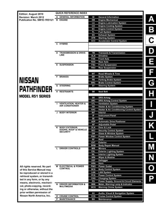
QUICK REFERENCE INDEX
A GENERAL INFORMATION GI General Information
B ENGINE EM Engine Mechanical
LU Engine Lubrication System
CO Engine Cooling System
EC Engine Control System
FL Fuel System
EX Exhaust System
STR Starting System
ACC Accelerator Control System
C HYBRID
D TRANSMISSION & DRIVE-
LINE
TM Transaxle & Transmission
DLN Driveline
FAX Front Axle
RAX Rear Axle
E SUSPENSION FSU Front Suspension
RSU Rear Suspension
WT Road Wheels & Tires
F BRAKES BR Brake System
PB Parking Brake System
BRC Brake Control System
G STEERING ST Steering System
H RESTRAINTS SB Seat Belt
SR SRS Airbag
SRC SRS Airbag Control System
I VENTILATION, HEATER &
AIR CONDITIONER
VTL Ventilation System
HA Heater & Air Conditioning System
HAC Heater & Air Conditioning Control System
J BODY INTERIOR INT Interior
IP Instrument Panel
SE Seat
ADP Automatic Drive Postioner
AP Adjustable Pedal
K BODY EXTERIOR,
DOORS, ROOF & VEHICLE
SECURITY
DLK Door & Lock
SEC Security Control System
GW Glass & Window System
PWC Power Window Control System
RF Roof
EXT Exterior
BRM Body Repair Manual
L DRIVER CONTROLS MIR Mirrors
EXL Exterior Lighting System
INL Interior Lighting System
WW Wiper & Washer
DEF Defogger
HRN Horn
M ELECTRICAL & POWER
CONTROL
PWO Power Outlet
BCS Body Control System
LAN LAN System
PCS Power Control System
CHG Charging System
PG Power Supply, Ground & Circuit Elements
N DRIVER INFORMATION &
MULTIMEDIA
MWI Meter, Warning Lamp & Indicator
WCS Warning Chime System
AV Audio, Visual & Navigation System
O CRUISE CONTROL CCS Cruise Control System
P MAINTENANCE MA Maintenance
All rights reserved. No part
of this Service Manual may
be reproduced or stored in a
retrieval system, or transmit-
ted in any form, or by any
means, electronic, mechani-
cal, photo-copying, record-
ing or otherwise, without the
prior written permission of
Nissan North America, Inc.
Edition: August 2010
Revision: March 2012
Publication No. SM1E-1R51U1
2. FOREWORD
This manual contains maintenance and repair procedure for the 2011
NISSAN PATHFINDER.
In order to assure your safety and the efficient functioning of the vehicle,
this manual should be read thoroughly. It is especially important that the
PRECAUTIONS in the GI section be completely understood before starting
any repair task.
All information in this manual is based on the latest product information
at the time of publication. The right is reserved to make changes in specifi-
cations and methods at any time without notice.
IMPORTANT SAFETY NOTICE
The proper performance of service is essential for both the safety of
the technician and the efficient functioning of the vehicle.
The service methods in this Service Manual are described in such a
manner that the service may be performed safely and accurately.
Service varies with the procedures used, the skills of the technician
and the tools and parts available. Accordingly, anyone using service
procedures, tools or parts which are not specifically recommended
by NISSAN must first be completely satisfied that neither personal
safety nor the vehicle’s safety will be jeopardized by the service
method selected.
3. 2011
QUICK REFERENCE CHART: PATHFINDER
QUICK REFERENCE CHART: PATHFINDER
Engine Tune Data: VQ40DE INFOID:0000000006840757
GENERAL SPECIFICATIONS
DRIVE BELT
SPARK PLUG
Cylinder arrangement V-6
Displacement cm3
(cu in) 3,954 (241.30)
Bore and stroke mm (in) 95.5 × 92.0 (3.76 × 3.622)
Valve arrangement DOHC
Firing order 1-2-3-4-5-6
Number of piston rings
Compression 2
Oil 1
Number of main bearings 4
Compression ratio 9.7
Compression pressure
kPa (kg/cm2
, psi)/300 rpm
Standard 1,275 (13.0, 185)
Minimum 981 (10.0, 142)
Differential limit between cylinders 98 (1.0, 14)
Cylinder number
Valve timing
(Intake valve timing control - “OFF”)
Unit: degree
a b c d e f
244 240 −4 64 6 58
SEM713A
PBIC0187E
Tension of drive belts Auto adjustment by auto tensioner
4. QUICK REFERENCE CHART: PATHFINDER
2011
*: Always check with the Parts Department for the latest parts information
Engine Tune-up Data: VK56DE INFOID:0000000006840756
GENERAL SPECIFICATIONS
DRIVE BELTS
Application United States and Canada Mexico
Make NGK
Standard type* DILFR5A-11 PLFR5A-11
Gap (nominal) 1.1 mm (0.043 in)
Cylinder arrangement V-8
Displacement cm3 (in3) 5,552 (338.80)
Bore and stroke mm (in) 98 x 92 (3.86 x 3.62)
Valve arrangement DOHC
Firing order 1-8-7-3-6-5-4-2
Number of piston rings
Compression 2
Oil 1
Number of main bearings 5
Compression ratio 9.8:1
Compression pressure
kPa (kg/cm2
, psi)/rpm
Standard 1,520 (15.5, 220)/200
Minimum 1,324 (13.5, 192)/200
Differential limit between cylinders 98 (1.0, 14)/200
Cylinder number
Valve timing
Unit: degree
a b c d e f
244° 232° 8° 60° 10° 54°
SEM957C
PBIC0187E
5. 2011
QUICK REFERENCE CHART: PATHFINDER
SPARK PLUG
Unit: mm (in)
*: Always check with the Parts Department for the latest parts information
Front Wheel Alignment (Unladen*1) INFOID:0000000006840755
*1: Fuel, radiator coolant and engine oil full. Spare tire, jack, hand tools and mats in designated positions.
*2: Target value 35° 26′ (35.43°)
*3: Target value 31° 22′ (31.37°)
*4: Target value 35° 33′ (35.55°)
*5: Target value 31° 38′ (31.63°)
Tension of drive belts Auto adjustment by auto tensioner
Make NGK
Standard type* DILFR5A-11
Gap (nominal) 1.1 (0.043)
Drive type 2WD 4WD
Camber
Degree minute (decimal degree)
Minimum -0° 30′ (-0.50°) -0° 15′ (-0.25°)
Nominal 0° 15′ (0.25°) 0° 30′ (0.50°)
Maximum 1° 00′ (1.00°) 1° 15′ (1.25°)
Cross cam-
ber
0° 45′ (0.75°) or less 0° 45′ (0.75°) or less
Caster
Degree minute (decimal degree)
Minimum 2° 15′ (2.25°) 2° 00′ (2.00°)
Nominal 3° 0′ (3.00°) 2° 45′ (2.75°)
Maximum 3° 45′ (3.75°) 3° 30′ (3.50°)
Cross caster 0° 45′ (0.75°) or less 0° 45′ (0.75°) or less
Kingpin inclination
Degree minute (decimal degree)
Nominal 13° 0′ (13.00°) 12° 45′ (12.75°)
Total toe-in
Distance (A − B)
Minimum In 1.2 mm (0.05 in) In 1.2 mm (0.05 in)
Nominal In 3.2 mm (0.12 in) In 3.2 mm (0.12 in)
Maximum In 5.2 mm (0.20 in) In 5.2 mm (0.20 in)
Angle (left wheel or right wheel)
Degree minute (decimal degree)
Minimum In 0° 4′ 48″ ( 0.08°) In 0° 4′ 48″ ( 0.08°)
Nominal In 0° 14′ 24″ (0.24°) In 0° 14′ 24″ (0.24°)
Maximum In 0° 24′ (0.40°) In 0° 24′ (0.40°)
Wheel turning angle (full turn)
Inside
Degree minute (Decimal de-
gree)
33° 26′– 35° 26′ *2
(33.43°– 35.43°)
33° 33′– 35° 33′ *4
(33.55°– 35.55°)
Outside
Degree minute (Decimal de-
gree)
29° 22′– 31° 22′ *3
(29.37°– 31.37°)
29° 38′– 31° 38′ *5
(29.63°– 31.63°)
SFA234AC
6. QUICK REFERENCE CHART: PATHFINDER
2011
Rear Wheel Alignment (Unladen*) INFOID:0000000006840753
*1: Fuel, radiator coolant and engine oil full. Spare tire, jack, hand tools and mats in designed positions.
Wheelarch Height (Unladen*1
) INFOID:0000000006840754
Unit: mm (in)
*1: Fuel, radiator coolant and engine oil full. Spare tire, jack, hand tools and mats in designated positions.
Camber
Degree minute (decimal degree)
Minimum - 0° 32′ (- 0.53°)
Nominal - 0° 2′ (- 0.03°)
Maximum 0° 28′ (0.47°)
Total toe-in
Distance (A – B)
Minimum Out 1.4 mm (0.05 in)
Nominal In 1.9 mm (0.07 in)
Maximum In 5.2 mm (0.20 in)
Angle
Degree minute (decimal degree)
Minimum Out 0° 3′ 36″ (0.06°)
Nominal In 0° 8′ 24″ (0.14°)
Maximum In 0° 20′ 24″ (0.34°)
ALEIA0059ZZ
Engine VQ40DE VK56DE
Drive type 2WD 4WD 4WD
Tire size P245/75R16 P265/65R17 P265/60R18 P245/75R16 P265/65R17 P265/60R18 P265/60R18
Front wheelarch height
(Hf)
867
(34.13)
865
(34.06)
867
(34.13)
875
(34.45)
874
(34.41)
891
(35.08)
876
(34.49)
Rear wheelarch height
(Hr)
875
(34.45)
873
(34.37)
875
(34.45)
884
(34.80)
883
(34.76)
901
(35.47)
886
(34.88)
LEIA0085E
7. 2011
QUICK REFERENCE CHART: PATHFINDER
Brake Specifications INFOID:0000000008526413
Unit: mm (in)
Brake Pedal INFOID:0000000008526414
ADJUSTABLE PEDAL
Unit: mm (in)
CAUTION:
When equipped with adjustable pedal, the pedal must be in the forward most position (closest to the floor) for pedal height
adjustment.
STANDARD PEDAL
Application VQ40 VK56
Front brake Brake model CLZ33VB
Rotor outer diameter × thickness 296 × 28 (11.654 × 1.102) 320 x 28 (12.598 x 1.102)
Pad Length × width × thickness
140 × 50.5 × 10.0 (5.512 × 1.988 ×
0.394)
130 × 52.3 × 11.0 (5.118 × 2.059 ×
0.433)
Cylinder bore diameter (each) 46.4 (1.827) 45.0 (1.772)
Rear brake Brake model CLZ14VB
Rotor outer diameter × thickness 308 × 18 (12.126 × 0.709)
Pad Length × width × thickness 87.6 × 37.0 × 11.0 (3.449 × 1.457 × 0.433)
Cylinder bore diameter 38.1 (1.500)
Control valve Valve model Electric brake force distribution
Brake booster
Booster model C215T
Diaphragm diameter 215 (8.465)
Pedal free height (H) with pedal in forward most position 182.1 (7.17)
Pedal full stroke (T) 153 (6.02)
Clearance between brake pedal bracket and threaded end of stop lamp switch and ASCD
cancel switch
0.74 - 1.96 (0.029 - 0.077)
ALFIA0149ZZ
8. QUICK REFERENCE CHART: PATHFINDER
2011
Unit: mm (in)
Front Disc Brake INFOID:0000000008526415
Unit: mm (in)
Rear Disc Brake INFOID:0000000008526416
Unit: mm (in)
Pedal free height (H) 182.1 (7.17)
Pedal full stroke (S) 153 (6.02)
Clearance between brake pedal bracket (C1) and threaded end of stop lamp switch and
ASCD cancel switch (C2)
0.74 - 1.96 (0.029 - 0.077)
AWFIA0433ZZ
Brake model CLZ33VB
Applied model VQ40DE VK56DE
Brake pad
Standard thickness (new) 10.0 (0.394) 11.0 (0.043)
Minimum thickness 2.0 (0.079)
Disc rotor
Standard thickness (new) 28.0 (1.102)
Minimum thickness 26.0 (1.024)
Maximum uneven wear (measured at 8 positions) 0.015 (0.0006)
Runout limit (with it attached to the vehicle) 0.05 (0.0020)
Brake model CLZ14VB
Brake pad
Standard thickness (new) 11.0 (0.433)
Minimum thickness 2.0 (0.079)
Disc rotor
Standard thickness (new) 18.0 (0.709)
Minimum thickness 16.0 (0.630)
Maximum uneven wear (measured at 8 positions) 0.015 (0.0006)
Runout limit (with it attached to the vehicle) 0.05 (0.0020)
9. 2011
QUICK REFERENCE CHART: PATHFINDER
FOR USA AND CANADA : Fluids and Lubricants INFOID:0000000008526412
FOR MEXICO : Fluids and Lubricants INFOID:0000000006840746
Description
Capacity (Approximate)
Metric US measure Imp measure
Fuel 80 21 1/8 gal 17 5/8 gal
Engine oil
Drain and refill
With oil filter
change
VQ40DE 5.1 5 3/8 qt 4 1/2 qt
VK56DE 6.5 6 7/8 qt 5 3/4 qt
Without oil filter
change
VQ40DE 4.8 5 1/8 qt 4 1/4 qt
VK56DE 6.2 6 1/2 qt 5 1/2 qt
Dry engine (engine overhaul) VQ40DE 6.3 6 5/8 qt 5 1/2 qt
VK56DE 7.6 8 qt 6 3/4 qt
Cooling system
(with reservoir at “MAX” lev-
el)
Without rear A/C VQ40DE 10.2 10 3/4 qt 9 qt
With rear
A/C
VQ40DE
VK56DE
13.4 14 1/8 qt 11 3/4 qt
Automatic transmission fluid (ATF)
VQ40DE 10.3 10 7/8 qt 9 1/8 qt
VK56DE 10.6 11 1/4 qt 9 3/8 qt
Rear final drive oil
VQ40DE 1.4 3 pt 2 1/2 pt
VK56DE 1.75 3 3/4 pt 3 1/8 pt
Transfer fluid
ATX14B 3.0 3 1/8 qt 2 5/8 qt
TX15B 2.0 2 1/8 qt 1 3/4 qt
Front final drive oil
VQ40DE 0.85 1 3/4 pt 1 1/2 pt
VK56DE 1.6 3 3/8 pt 2 7/8 pt
Power steering fluid (PSF) 1.0 2 1/8 pt 1 3/4 pt
Brake fluid — — —
Multi-purpose grease — — —
Windshield washer fluid 4.5 1 1/4 gal 1 gal
A/C system
refrigerant
Without rear A/C 0.70 ± 0.05 kg 1.54 ± 0.11 lb 1.54 ± 0.11 lb
With rear A/C 0.85 ± 0.05 kg 1.87 ± 0.11 lb 1.87 ± 0.11 lb
A/C system oil
Without rear A/C 180 m 6.1 fl oz 6.3 fl oz
With Rear A/C 210 m 7.1 fl oz 7.4 fl oz
Description
Capacity (Approximate)
Metric US measure Imp measure
Fuel 80 21 1/8 gal 17 5/8 gal
Engine oil
Drain and refill
With oil filter change 5.1 5 3/8 qt 4 1/2 qt
Without oil filter change 4.8 5 1/8 qt 4 1/4 qt
Dry engine (engine overhaul) 6.3 6 5/8 qt 5 1/2 qt
Cooling system
(with reservoir at “MAX” level)
10.2 10 3/4 qt 9 qt
Automatic transmission fluid (ATF) 10.3 10 7/8 qt 9 1/8 qt
10. QUICK REFERENCE CHART: PATHFINDER
2011
Rear final drive oil 1.4 3 pt 2 1/2 pt
Transfer fluid ATX14B 3.0 3 1/8 qt 2 5/8 qt
Front final drive oil 0.85 1 3/4 pt 1 1/2 pt
Power steering fluid (PSF) 1.0 2 1/8 pt 1 3/4 pt
Brake fluid — — —
Multi-purpose grease — — —
Windshield washer fluid 4.5 1 1/4 gal 1 gal
A/C system refrigerant 0.85 ± 0.05 kg 1.87 ± 0.11 lb 1.87 ± 0.11 lb
A/C system oil 210 m 7.1 fl oz 7.4 fl oz
Description
Capacity (Approximate)
Metric US measure Imp measure
11. GI-1
GENERAL INFORMATION
C
D
E
F
G
H
I
J
K
L
M
B
GI
SECTION GI
N
O
P
CONTENTS
GENERAL INFORMATION
HOW TO USE THIS MANUAL ..................
.... 3
HOW TO USE THIS MANUAL .......................
..... 3
Description ..........................................................
......3
Terms ..................................................................
......3
Units ....................................................................
......3
Contents ..............................................................
......3
Relation between Illustrations and Descriptions .
......4
Components ........................................................
......4
HOW TO FOLLOW TROUBLE DIAGNOSES..... 6
Description ..........................................................
......6
How to Follow Test Groups in Trouble Diagnosis......6
Key to Symbols Signifying Measurements or Pro-
cedures ...............................................................
......7
HOW TO READ WIRING DIAGRAMS ...........
..... 9
Connector symbols .............................................
......9
Sample/wiring diagram -example- .......................
....10
Description ..........................................................
....11
ABBREVIATIONS ..........................................
....13
Abbreviation List ..................................................
....13
RECOMMENDED CHEMICAL PRODUCTS
AND SEALANTS ............................................
....14
Recommended Chemical Products and Sealants
....14
TERMINOLOGY .............................................
....15
ISO 15031-2 Terminology List ............................
....15
TIGHTENING TORQUE OF STANDARD
BOLTS ............................................................
....19
Tightening Torque Table .....................................
....19
FEATURES OF NEW MODEL ..................
...20
IDENTIFICATION INFORMATION .................
....20
Model Variation ...................................................
....20
Identification Number ..........................................
....21
Dimensions .........................................................
....23
Wheels & Tires ....................................................
....23
PRECAUTION ...........................................
...24
PRECAUTIONS .................................................24
Description ...........................................................
....24
Precaution for Supplemental Restraint System
(SRS) "AIR BAG" and "SEAT BELT PRE-TEN-
SIONER" .............................................................
....24
Precaution Necessary for Steering Wheel Rota-
tion After Battery Disconnect ...............................
....24
General Precaution ..............................................
....25
Precaution for All Mode 4WD System .................
....26
Precaution for Three Way Catalyst ......................
....26
Precaution for Fuel (Unleaded Premium Gasoline
Recommended) ...................................................
....26
Precaution for Multiport Fuel Injection System or
Engine Control System ........................................
....27
Precaution for Hoses ...........................................
....27
Precaution for Engine Oils ...................................
....28
Precaution for Air Conditioning ............................
....28
LIFTING POINT .................................................29
Pantograph Jack ..................................................
....29
Garage Jack and Safety Stand ............................
....29
2-Pole Lift ............................................................
....29
TOW TRUCK TOWING .....................................31
Tow Truck Towing ...............................................
....31
Vehicle Recovery (Freeing a Stuck Vehicle) .......
....32
BASIC INSPECTION ................................
...33
SERVICE INFORMATION FOR ELECTRICAL
INCIDENT ..........................................................33
Work Flow ............................................................
....33
Control Units and Electrical Parts ........................
....33
How to Check Terminal .......................................
....34
Intermittent Incident .............................................
....37
Circuit Inspection .................................................
....40
CONSULT-III CHECKING SYSTEM .................45
Description ...........................................................
....45
Function and System Application ........................
....45
Revision: March 2012 2011 Pathfinder
12. GI-2
CONSULT-III Data Link Connector (DLC) Circuit... 45
WIRING DIAGRAM ..................................
... 47
CONSULT-III CHECKING SYSTEM ...............
... 47
Wiring Diagram ....................................................
... 47
Revision: March 2012 2011 Pathfinder
13. HOW TO USE THIS MANUAL
GI-3
< HOW TO USE THIS MANUAL >
C
D
E
F
G
H
I
J
K
L
M
B
GI
N
O
P
HOW TO USE THIS MANUAL
HOW TO USE THIS MANUAL
Description INFOID:0000000006243337
This volume explains “Removal, Disassembly, Installation, Inspection and Adjustment” and “Trouble Diag-
noses”.
Terms INFOID:0000000006243338
• The captions WARNING and CAUTION warn you of steps that must be followed to prevent personal injury
and/or damage to some part of the vehicle.
WARNING indicates the possibility of personal injury if instructions are not followed.
CAUTION indicates the possibility of component damage if instructions are not followed.
BOLD TYPED STATEMENTS except WARNING and CAUTION give you helpful information.
Standard value:Tolerance at inspection and adjustment.
Limit value:The maximum or minimum limit value that should not be exceeded at inspection and adjustment.
Units INFOID:0000000006243339
• The UNITS given in this manual are primarily expressed as the SI UNIT (International System of Unit), and
alternatively expressed in the metric system and in the yard/pound system.
Also with regard to tightening torque of bolts and nuts, there are descriptions both about range and about the
standard tightening torque.
“Example”
Range
Standard
Contents INFOID:0000000006243340
• A QUICK REFERENCE INDEX, a black tab (e.g. ) is provided on the first page. You can quickly find the
first page of each section by matching it to the section's black tab.
• THE CONTENTS are listed on the first page of each section.
• THE TITLE is indicated on the upper portion of each page and shows the part or system.
• THE PAGE NUMBER of each section consists of two or three letters which designate the particular section
and a number (e.g. “BR-5”).
• THE SMALL ILLUSTRATIONS show the important steps such as inspection, use of special tools, knacks of
work and hidden or tricky steps which are not shown in the previous large illustrations.
Assembly, inspection and adjustment procedures for the complicated units such as the automatic transaxle
or transmission, etc. are presented in a step-by-step format where necessary.
Outer Socket Lock Nut : 59 - 78 N·m (6.0 - 8.0 kg-m, 43 - 58 ft-lb)
Drive Shaft Installation Bolt : 44.3 N·m (4.5 kg-m, 33 ft-lb)
Revision: March 2012 2011 Pathfinder
14. GI-4
< HOW TO USE THIS MANUAL >
HOW TO USE THIS MANUAL
Relation between Illustrations and Descriptions INFOID:0000000006243341
The following sample explains the relationship between the part description in an illustration, the part name in
the text and the service procedures.
Components INFOID:0000000006243342
• THE LARGE ILLUSTRATIONS are exploded views (see the following) and contain tightening torques, lubri-
cation points, section number of the PARTS CATALOG (e.g. SEC. 440) and other information necessary to
perform repairs.
The illustrations should be used in reference to service matters only. When ordering parts, refer to the appro-
priate PARTS CATALOG.
Always check with the PARTS DEPARMENT for the latest parts information.
Components shown in an illustration may be identified by a circled number. When this style of illustration is
used, the text description of the components will follow the illustration.
SAIA0519E
Revision: March 2012 2011 Pathfinder
15. HOW TO USE THIS MANUAL
GI-5
< HOW TO USE THIS MANUAL >
C
D
E
F
G
H
I
J
K
L
M
B
GI
N
O
P
SYMBOLS
1. Union bolt 2. Copper washer 3. Brake hose
4. Cap 5. Bleed valve 6. Sliding pin bolt
7. Piston seal 8. Piston 9. Piston boot
10. Cylinder body 11. Sliding pin 12. Torque member mounting bolt
13. Washer 14. Sliding pin boot 15. Bushing
16. Torque member 17. Inner shim cover 18. Inner shim
19. Inner pad 20. Pad retainer 21. Pad wear sensor
22. Outer pad 23. Outer shim 24. Outer shim cover
1: PBC (Poly Butyl Cuprysil) grease
or silicone-based grease
2: Rubber grease : Brake fluid
Refer to GI section for additional symbol definitions.
SFIA2959E
SAIA0749E
Revision: March 2012 2011 Pathfinder