
Recommended
More Related Content
Similar to 2009 Nissan Armada Service Repair Manual.pdf
Similar to 2009 Nissan Armada Service Repair Manual.pdf (14)
More from jjkdmsmmd
More from jjkdmsmmd (20)
Recently uploaded
Recently uploaded (20)
2009 Nissan Armada Service Repair Manual.pdf
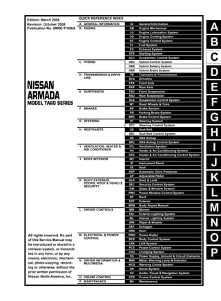
- 1. A B C D E F G H I J K L M N P O QUICK REFERENCE INDEX A GENERAL INFORMATION GI General Information B ENGINE EM Engine Mechanical LU Engine Lubrication System CO Engine Cooling System EC Engine Control System FL Fuel System EX Exhaust System STR Starting System ACC Accelerator Control System C HYBRID HBC Hybrid Control System HBB Hybrid Battery System HBR Hybrid Brake System D TRANSMISSION & DRIVE- LINE TM Transaxle & Transmission DLN Driveline FAX Front Axle RAX Rear Axle E SUSPENSION FSU Front Suspension RSU Rear Suspension SCS Suspension Control System WT Road Wheels & Tires F BRAKES BR Brake System PB Parking Brake System BRC Brake Control System G STEERING ST Steering System STC Steering Control System H RESTRAINTS SB Seat Belt SBC Seat Belt Control System SR SRS Airbag SRC SRS Airbag Control System I VENTILATION, HEATER & AIR CONDITIONER VTL Ventilation System HA Heater & Air Conditioning System HAC Heater & Air Conditioning Control System J BODY INTERIOR INT Interior IP Instrument Panel SE Seat ADP Automatic Drive Postioner AP Adjustable Pedal K BODY EXTERIOR, DOORS, ROOF & VEHICLE SECURITY DLK Door & Lock SEC Security Control System GW Glass & Window System PWC Power Window Control System RF Roof EXT Exterior BRM Body Repair Manual L DRIVER CONTROLS MIR Mirrors EXL Exterior Lighting System INL Interior Lighting System WW Wiper & Washer DEF Defogger HRN Horn M ELECTRICAL & POWER CONTROL PWO Power Outlet BCS Body Control System LAN LAN System PCS Power Control System CHG Charging System PG Power Supply, Ground & Circuit Elements N DRIVER INFORMATION & MULTIMEDIA MWI Meter, Warning Lamp & Indicator WCS Warning Chime System SN Sonar System AV Audio, Visual & Navigation System O CRUISE CONTROL CCS Cruise Control System P MAINTENANCE MA Maintenance All rights reserved. No part of this Service Manual may be reproduced or stored in a retrieval system, or transmit- ted in any form, or by any means, electronic, mechani- cal, photo-copying, record- ing or otherwise, without the prior written permission of Nissan North America, Inc. Edition: March 2008 Revision: October 2008 Publication No. SM9E-1T60U0
- 2. FOREWORD This manual contains maintenance and repair procedure for the 2009 NISSAN ARMADA. In order to assure your safety and the efficient functioning of the vehicle, this manual should be read thoroughly. It is especially important that the PRECAUTIONS in the GI section be completely understood before starting any repair task. All information in this manual is based on the latest product information at the time of publication. The right is reserved to make changes in specifi- cations and methods at any time without notice. IMPORTANT SAFETY NOTICE The proper performance of service is essential for both the safety of the technician and the efficient functioning of the vehicle. The service methods in this Service Manual are described in such a manner that the service may be performed safely and accurately. Service varies with the procedures used, the skills of the technician and the tools and parts available. Accordingly, anyone using service procedures, tools or parts which are not specifically recommended by NISSAN must first be completely satisfied that neither personal safety nor the vehicle’s safety will be jeopardized by the service method selected.
- 3. 2009 QUICK REFERECNE CHART: ARMADA QUICK REFERENCE CHART: ARMADA QUICK REFERECNE CHART: ARMADA INFOID:0000000001679742 Engine Tune-up Data Cylinder arrangement V-8 Displacement cm3 (in3 ) 5,552 (338.80) Bore and stroke mm (in) 98 x 92 (3.86 x 3.62) Valve arrangement DOHC Firing order 1-8-7-3-6-5-4-2 Number of piston rings Compression 2 Oil 1 Number of main bearings 5 Compression ratio 9.8:1 Compression pressure kPa (kg/cm2, psi)/rpm Standard 1,520 (15.5, 220)/200 Minimum 1,324 (13.5, 192)/200 Differential limit between cylinders 98 (1.0, 14)/200 Cylinder number Valve timing Unit: degree a b c d e f 244° 232° -8° 60° 10° 54° SEM957C PBIC0187E
- 4. QUICK REFERECNE CHART: ARMADA 2009 Front Wheel Alignment (Unladen*1 ) INFOID:0000000001679743 *1: Fuel, radiator coolant and engine oil full. Spare tire, jack, hand tools and mats in designated positions. *2: Target value 37° 31′ (37.52°) *3: Target value 33° 59′ (33.98°) *4: Target value 37° 44′ (37.73°) *5: Target value 33° 29′ (33.48°) Rear Wheel Alignment (Unladen*1 ) INFOID:0000000001679745 Drive type 2WD 4WD Suspension Standard Air leveling Standard Air leveling Camber Degree minute (decimal degree) Minimum -0° 51′ (-0.85°) -0° 33′ (-0.55°) Nominal -0° 6′ (-0.10°) 0° 12′ (0.20°) Maximum 0° 39′ (0.65°) 0° 57′ (0.95°) Cross camber 0° 45′ (0.75°) or less 0° 45′ (0.75°) or less Caster Degree minute (decimal degree) Minimum 2° 21′ (2.35°) 3° 15′ (3.25°) 2° 15′ (2.25°) 2°45′ (2.75°) Nominal 3° 24′ (3.40°) 4° 0′ (4.00°) 3° 0′ (3.00°) 3° 30′ (3.50°) Maximum 4° 09′ (4.15°) 4° 45′ (4.75°) 3° 45′ (3.75°) 4° 15′ (4.25°) Cross caster 0° 45′ (0.75°) or less 0° 45′ (0.75°) or less Kingpin inclination Degree minute (decimal degree) 13° 32′ (13.53°) 13°13′ (13.22°) Total toe-in Distance (A − B) Minimum 1.8 mm (0.07 in) 1.8 mm (0.07 in) Nominal 2.8 mm (0.11 in) 2.8 mm (0.11 in) Maximum 3.8 mm (0.15 in) 3.8 mm (0.15 in) Angle (left side and right side) Degree minute (decimal degree) Minimum 0° 3′ (0.05°) 0° 3′ (0.05°) Nominal 0° 5′ (0.08°) 0° 5′ (0.08°) Maximum 0° 7′ (0.12°) 0° 7′ (0.12°) Wheel turning angle (full turn) Inside Degree minute (decimal degree) 34° 31′ – 38° 31′ *2 (34.52° – 38.52°) 34° 44′ – 38° 44′ *4 (34.73° – 38.73°) Outside Degree minute (decimal degree) 30° 59′ – 34° 59′ *3 (30.98° – 34.98°) 30° 29′ – 34° 29′ *5 (30.48° – 34.48°) SFA234AC Applied model Without air leveling With air leveling Camber Degree minute (decimal degree) Minimum - 0° 25′ (- 0.4°) - 1° 0′ (- 1°) Nominal 0° 5′ (0.1°) - 0° 30′ (- 0.5°) Maximum 0° 35′ (0.6°) 0° 0′ (0°) Cross camber 0° 45' (0.75°) or less
- 5. 2009 QUICK REFERECNE CHART: ARMADA *1: Fuel tank, engine coolant and engine oil full. Spare tire, jack, hand tools and mats in designated positions. Wheelarch Height (Unladen*) INFOID:0000000001679744 Unit: mm (in) *: Fuel, radiator coolant and engine oil full. Spare tire, jack, hand tools and mats in designated positions. Brake Specification INFOID:0000000003243556 Unit: mm (in) Total toe-in Distance (A - B) Minimum - 2.4 mm (- 0.094 in) 0 mm (0 in) Nominal 0.9 mm (0.035 in) 3.3 mm (0.130 in) Maximum 4.2 mm (0.165 in) 6.6 mm (0.260 in) Cross toe 2 mm (0.079 in) or less Angle (left side and right side) Degree minute (decimal degree) Minimum - 0° 5' (- 0.8°) 0° 0' (0°) Nominal 0° 2' (0.03°) 0° 7' (0.11°) Maximum 0° 9' (0.14°) 0° 14' (0.22°) Cross toe 0° 8' (0.14°) or less SFA234AC Suspension type With air leveling Without air leveling Applied model 2WD 4WD 2WD 4WD Tire size P265/ 70R18 P275/ 60R20 P265/ 70R18 P275/ 60R20 P265/ 70R18 P275/ 60R20 P265/ 70R18 P275/ 60R20 Front wheelarch height (Hf) 914 (35.98) 920 (36.22) 931 (36.65) 937 (36.89) 914 (35.98) 920 (36.22) 931 (36.65) 937 (36.89) Rear wheelarch height (Hr) 911 (35.87) 917 (36.10) 931 (36.65) 937 (36.89) 931 (36.65) 937 (36.89) 951 (37.44) 957 (37.68) LEIA0085E Front brake Brake model CLZ31VC Rotor outer diameter × thickness 350 × 30 (13.80 × 1.2) Pad Length × width × thickness 111.0 × 73.5 × 11.88 (4.73 × 2.894 × 0.374) Cylinder bore diameter (each) 51 (2.01)
- 6. QUICK REFERECNE CHART: ARMADA 2009 Brake Pedal INFOID:0000000003243557 When equipped with adjustable pedal, the pedal must be in the forward most (closest to the floor) position for pedal height measure- ment. Front Disc Brake INFOID:0000000003243558 Rear Disc Brake INFOID:0000000003243559 Fluids and Lubricants INFOID:0000000001679750 Rear brake Brake model AD14VE Rotor outer diameter × thickness 320 × 14 (12.60 × 0.6) Pad Length × width × thickness 83.0 × 33.0 × 8.5 (3.268 × 1.299 × 0.335) Cylinder bore diameter 48 (1.89) Control valve Valve model Electric brake force distribution Brake booster Booster model C215T Diaphragm diameter 215 (8.46) Brake pedal height (from dash panel top surface) 182.3 − 192.3 mm (7.18 − 7.57 in) Depressed pedal height [under a force of 490 N (50 kg-f, 110 lb-f) with engine running] More than 90.3 mm (3.55 in) Clearance between stopper rubber and the threaded end of stop lamp switch and ASCD cancel switch 0.74 − 1.96 mm (0.029 − 0.077 in) Pedal play 3 − 11 mm (0.12 − 0.43 in) Brake model CLZ31VC Brake pad Standard thickness (new) 11.88 mm (0.468 in) Repair limit thickness 1.0 mm (0.039 in) Disc rotor Standard thickness (new) 26.0 mm (1.024 in) Repair limit thickness 24.5 mm (0.965 in) Maximum uneven wear (measured at 8 positions) 0.015mm (0.0006 in) Runout limit (with it attached to the vehicle) 0.03 mm (0.001 in) Brake model AD14VE Brake pad Standard thickness (new) 12.13 mm (0.478 in) Repair limit thickness 1.0 mm (0.039 in) Disc rotor Standard thickness (new) 14.0 mm (0.551 in) Repair limit thickness 12.0 mm (0.472 in) Maximum uneven wear (measured at 8 positions) 0.015 mm (0.0006 in) Runout limit (with it attached to the vehicle) 0.07 mm (0.003 in) Description Capacity (Approximate) Metric US measure Imp measure Fuel 105.8 28 gal 23 1/4 gal Engine oil Drain and refill With oil filter change 6.2 6 1/2 qt 5 1/2 qt Without oil filter change 5.9 6 1/4 qt 5 1/4 qt Dry engine (engine overhaul) 7.6 8 qt 6 3/4 qt
- 7. 2009 QUICK REFERECNE CHART: ARMADA Cooling system With reservoir at MAX level 12.2 3 1/4 gal 2 5/8 gal Automatic transmission fluid (ATF) 10.6 11 1/4 qt 9 3/8 qt Rear final drive oil 2.01 4 1/4 pt 3 1/2 pt Transfer fluid 2.0 2 1/8 qt 1 3/4 qt Front final drive oil 1.6 3 3/8 pt 2 7/8 pt Power steering fluid (PSF) 1.0 2 1/8 pt 1 3/4 pt Brake fluid — — — Multi-purpose grease — — — Brake grease — — — Windshield washer fluid 4.5 1 1/4 gal 1 gal Air conditioning system refrigerant 0.70 ± 0.05 kg 1.54 ± 0.11 lb 1.54 ± 0.11 lb Air conditioning system oil 200 m 6.8 fl oz 7.0 fl oz Description Capacity (Approximate) Metric US measure Imp measure
- 8. GI-1 GENERAL INFORMATION C D E F G H I J K L M B GI SECTION GI N O P CONTENTS GENERAL INFORMATION HOW TO USE THIS MANUAL .................. .... 3 HOW TO USE THIS MANUAL ....................... ..... 3 Description .......................................................... ......3 Terms .................................................................. ......3 Units .................................................................... ......3 Contents .............................................................. ......3 Relation between Illustrations and Descriptions . ......4 Components ........................................................ ......4 HOW TO FOLLOW TROUBLE DIAGNOSES..... 6 Description .......................................................... ......6 How to Follow Test Groups in Trouble Diagnosis......6 Key to Symbols Signifying Measurements or Pro- cedures ............................................................... ......7 HOW TO READ WIRING DIAGRAMS ........... ..... 9 Connector symbols ............................................. ......9 Sample/wiring diagram -example- ....................... ....10 Description .......................................................... ....11 ABBREVIATIONS .......................................... ....13 Abbreviation List .................................................. ....13 TIGHTENING TORQUE OF STANDARD BOLTS ............................................................ ....14 Tightening Torque Table ..................................... ....14 RECOMMENDED CHEMICAL PRODUCTS AND SEALANTS ............................................ ....15 Recommended Chemical Products and Sealants ....15 TERMINOLOGY ............................................. ....16 SAE J1930 Terminology List ............................... ....16 FEATURES OF NEW MODEL .................. ...20 IDENTIFICATION INFORMATION ................. ....20 Model Variation ................................................... ....20 Identification Number .......................................... ....21 Dimensions ......................................................... ....22 Wheels & Tires .................................................... ....23 PRECAUTION ........................................... ...24 PRECAUTIONS .................................................24 Description ........................................................... ....24 Supplemental Restraint System (SRS) "AIR BAG" and "SEAT BELT PRE-TENSIONER" ................. ....24 Necessary for Steering Wheel Rotation After Bat- tery Disconnect .................................................... ....24 Procedures without Cowl Top Cover ................... ....25 General Precautions ............................................ ....25 Three Way Catalyst ............................................. ....26 Fuel (Regular Unleaded Gasoline Recommend- ed) ....................................................................... ....27 Multiport Fuel Injection System or Engine Control System ................................................................. ....27 Hoses .................................................................. ....27 Engine Oils .......................................................... ....28 Air Conditioning ................................................... ....28 LIFTING POINT .................................................29 Pantograph Jack .................................................. ....29 Garage Jack and Safety Stand ............................ ....29 2-Pole Lift ............................................................ ....29 TOW TRUCK TOWING .....................................31 Tow Truck Towing ............................................... ....31 Vehicle Recovery (Freeing a stuck vehicle) ........ ....32 BASIC INSPECTION ................................ ...33 SERVICE INFORMATION FOR ELECTRICAL INCIDENT ..........................................................33 Work Flow ............................................................ ....33 Control Units and Electrical Parts ........................ ....33 How to Check Terminal ....................................... ....34 Intermittent Incident ............................................. ....37 Circuit Inspection ................................................. ....40 CONSULT-III CHECKING SYSTEM .................45 Description ........................................................... ....45 Function and System Application ........................ ....45 CONSULT-III Data Link Connector (DLC) Circuit....46 Revision: October 2008 2009 Armada
- 9. GI-2 Wiring Diagram .................................................... ... 47 Revision: October 2008 2009 Armada
- 10. HOW TO USE THIS MANUAL GI-3 < HOW TO USE THIS MANUAL > C D E F G H I J K L M B GI N O P HOW TO USE THIS MANUAL HOW TO USE THIS MANUAL Description INFOID:0000000003708067 This volume explains “Removal, Disassembly, Installation, Inspection and Adjustment” and “Trouble Diag- noses”. Terms INFOID:0000000003708068 • The captions WARNING and CAUTION warn you of steps that must be followed to prevent personal injury and/or damage to some part of the vehicle. WARNING indicates the possibility of personal injury if instructions are not followed. CAUTION indicates the possibility of component damage if instructions are not followed. BOLD TYPED STATEMENTS except WARNING and CAUTION give you helpful information. Standard value: Tolerance at inspection and adjustment. Limit value: The maximum or minimum limit value that should not be exceeded at inspection and adjust- ment. Units INFOID:0000000003708069 • The UNITS given in this manual are primarily expressed as the SI UNIT (International System of Unit), and alternatively expressed in the metric system and in the yard/pound system. Also with regard to tightening torque of bolts and nuts, there are descriptions both about range and about the standard tightening torque. “Example” Range Standard Contents INFOID:0000000003708070 • ALPHABETICAL INDEX is provided at the end of this manual so that you can rapidly find the item and page you are searching for. • A QUICK REFERENCE INDEX, a black tab (e.g. ) is provided on the first page. You can quickly find the first page of each section by matching it to the section's black tab. • THE CONTENTS are listed on the first page of each section. • THE TITLE is indicated on the upper portion of each page and shows the part or system. • THE PAGE NUMBER of each section consists of two or three letters which designate the particular section and a number (e.g. “BR-5”). • THE SMALL ILLUSTRATIONS show the important steps such as inspection, use of special tools, knacks of work and hidden or tricky steps which are not shown in the previous large illustrations. Assembly, inspection and adjustment procedures for the complicated units such as the automatic transaxle or transmission, etc. are presented in a step-by-step format where necessary. Outer Socket Lock Nut : 59 - 78 N·m (6.0 - 8.0 kg-m, 43 - 58 ft-lb) Drive Shaft Installation Bolt : 44.3 N·m (4.5 kg-m, 33 ft-lb) Revision: October 2008 2009 Armada
- 11. GI-4 < HOW TO USE THIS MANUAL > HOW TO USE THIS MANUAL Relation between Illustrations and Descriptions INFOID:0000000003708071 The following sample explains the relationship between the part description in an illustration, the part name in the text and the service procedures. Components INFOID:0000000003708072 • THE LARGE ILLUSTRATIONS are exploded views (see the following) and contain tightening torques, lubri- cation points, section number of the PARTS CATALOG (e.g. SEC. 440) and other information necessary to perform repairs. The illustrations should be used in reference to service matters only. When ordering parts, refer to the appro- priate PARTS CATALOG. Components shown in an illustration may be identified by a circled number. When this style of illustration is used, the text description of the components will follow the illustration. SAIA0519E Revision: October 2008 2009 Armada
- 12. HOW TO USE THIS MANUAL GI-5 < HOW TO USE THIS MANUAL > C D E F G H I J K L M B GI N O P SYMBOLS 1. Union bolt 2. Copper washer 3. Brake hose 4. Cap 5. Bleed valve 6. Sliding pin bolt 7. Piston seal 8. Piston 9. Piston boot 10. Cylinder body 11. Sliding pin 12. Torque member mounting bolt 13. Washer 14. Sliding pin boot 15. Bushing 16. Torque member 17. Inner shim cover 18. Inner shim 19. Inner pad 20. Pad retainer 21. Pad wear sensor 22. Outer pad 23. Outer shim 24. Outer shim cover 1: PBC (Poly Butyl Cuprysil) grease or silicone-based grease 2: Rubber grease : Brake fluid Refer to GI section for additional symbol definitions. SFIA2959E SAIA0749E Revision: October 2008 2009 Armada
- 13. GI-6 < HOW TO USE THIS MANUAL > HOW TO FOLLOW TROUBLE DIAGNOSES HOW TO FOLLOW TROUBLE DIAGNOSES Description INFOID:0000000003708073 NOTICE: Trouble diagnoses indicate work procedures required to diagnose problems effectively. Observe the following instructions before diagnosing. • Before performing trouble diagnoses, read the “Work Flow” in each section. • After repairs, re-check that the problem has been completely eliminated. • Refer to Component Parts and Harness Connector Location for the Systems described in each section for identification/location of components and harness connectors. • When checking circuit continuity, ignition switch should be OFF. • Refer to the Circuit Diagram for quick pinpoint check. If you need to check circuit continuity between harness connectors in more detail, such as when a sub-har- ness is used, refer to Wiring Diagram in each individual section and Harness Layout in PG section for identi- fication of harness connectors. • Before checking voltage at connectors, check battery voltage. • After accomplishing the Diagnosis Procedures and Electrical Components Inspection, make sure that all harness connectors are reconnected as they were. How to Follow Test Groups in Trouble Diagnosis INFOID:0000000003708074 1. Test group number and test group title • Test group number and test group title are shown in the upper portion of each test group. 2. Work and diagnosis procedure • Start to diagnose a problem using procedures indicated in enclosed test groups. 3. Questions and results • Questions and required results are indicated in test group. 4. Action • Next action for each test group is indicated based on result of each question. JPAIA0021GB Revision: October 2008 2009 Armada
- 14. HOW TO FOLLOW TROUBLE DIAGNOSES GI-7 < HOW TO USE THIS MANUAL > C D E F G H I J K L M B GI N O P Key to Symbols Signifying Measurements or Procedures INFOID:0000000003708075 SAIA1539E Revision: October 2008 2009 Armada
- 15. GI-8 < HOW TO USE THIS MANUAL > HOW TO FOLLOW TROUBLE DIAGNOSES SAIA1540E Revision: October 2008 2009 Armada
- 16. HOW TO READ WIRING DIAGRAMS GI-9 < HOW TO USE THIS MANUAL > C D E F G H I J K L M B GI N O P HOW TO READ WIRING DIAGRAMS Connector symbols INFOID:0000000003708076 Most of connector symbols in wiring diagrams are shown from the terminal side. • Connector symbols shown from the terminal side are enclosed by a single line and followed by the direction mark. • Connector symbols shown from the harness side are enclosed by a double line and followed by the direction mark. • Certain systems and components, especially those related to OBD, may use a new style slide-locking type harness connector. For description and how to disconnect, refer to PG section, “Description”, “HARNESS CONNECTOR”. • Male and female terminals Connector guides for male terminals are shown in black and female terminals in white in wiring diagrams. SAIA0257E SGI363 Revision: October 2008 2009 Armada
- 17. GI-10 < HOW TO USE THIS MANUAL > HOW TO READ WIRING DIAGRAMS Sample/wiring diagram -example- INFOID:0000000003708077 • For detail, refer to following GI-11, "Description". JCAWA0005GB Revision: October 2008 2009 Armada
- 18. HOW TO READ WIRING DIAGRAMS GI-11 < HOW TO USE THIS MANUAL > C D E F G H I J K L M B GI N O P Description INFOID:0000000003708078 SWITCH POSITIONS Switches are shown in wiring diagrams as if the vehicle is in the “normal” condition. A vehicle is in the “normal” condition when: Number Item Description 1 Power supply • This means the power supply of fusible link or fuse. 2 Fusible link • “X” means the fusible link. 3 Number of fusible link/ fuse • This means the number of fusible link or fuse location. 4 Fuse • “/” means the fuse. 5 Current rating of fus- ible link/fuse • This means the current rating of the fusible link or fuse. 6 Optional splice • The open circle shows that the splice is optional depending on vehicle application. 7 Connector number • The letter shows which harness the connector is located in. • Example “M”: main harness. For detail and to locate the connector, refer to PG-63, "Elec- trical Units Location", PG-39, "Harness Layout". 8 Splice • The shaded circle “ ” means the splice. 9 Page crossing • This circuit continues to an adjacent page. 10 Option abbreviation • This means the vehicle specifications which layouts the circuit between “ ”. 11 Relay • This shows an internal representation of the relay. 12 Option description • This shows a description of the option abbreviation used on the page. 13 Switch • This shows that continuity exists between terminals 1 and 2 when the switch is in the A position. Continuity exists between terminals 1 and 3 when the switch is in the B position. 14 Circuit (Wiring) • This means the wiring. 15 System branch • This shows that the circuit is branched to other systems. 16 Shielded line • The line enclosed by broken line circle shows shield wire. 17 Component name • This shows the name of a component. 18 Ground (GND) • This shows the ground connection. 19 Connector • This means the connector information. • This unit-side is described by the connector symbols. 20 Connectors • This means that a transmission line bypasses two connectors or more. 21 Wire color • This shows a code for the color of the wire. B = Black W = White R = Red G = Green L = Blue Y = Yellow LG = Light Green BR = Brown OR or O = Orange P = Pink PU or V (Violet) = Purple GY or GR = Gray SB = Sky Blue CH = Dark Brown DG = Dark Green • When the wire color is striped, the base color is given first, followed by the stripe color as shown below: Example: L/W = Blue with White Stripe 22 Terminal number • This means the terminal number of a connector. Revision: October 2008 2009 Armada
- 19. GI-12 < HOW TO USE THIS MANUAL > HOW TO READ WIRING DIAGRAMS • ignition switch is “OFF”, • doors, hood and trunk lid/back door are closed, • pedals are not depressed, and • parking brake is released. MULTIPLE SWITCH The continuity of multiple switch is described in two ways as shown below. • The switch chart is used in schematic diagrams. • The switch diagram is used in wiring diagrams. SGI860 JSAIA0017GB Revision: October 2008 2009 Armada
- 20. ABBREVIATIONS GI-13 < HOW TO USE THIS MANUAL > C D E F G H I J K L M B GI N O P ABBREVIATIONS Abbreviation List INFOID:0000000003708079 The following ABBREVIATIONS are used: ABBREVIATION DESCRIPTION A/C Air Conditioner A/T Automatic Transaxle/Transmission ATF Automatic Transmission Fluid AWD All wheel drive D1 Drive range 1st gear D2 Drive range 2nd gear D3 Drive range 3rd gear D4 Drive range 4th gear FR, RR Front, Rear LH, RH Left-Hand, Right-Hand OD Overdrive P/S Power Steering SAE Society of Automotive Engineers, Inc. SDS Service Data and Specifications SST Special Service Tools 2WD 2-Wheel Drive 22 2nd range 2nd gear 21 2nd range 1st gear 12 1st range 2nd gear 11 1st range 1st gear Revision: October 2008 2009 Armada
- 21. GI-14 < HOW TO USE THIS MANUAL > TIGHTENING TORQUE OF STANDARD BOLTS TIGHTENING TORQUE OF STANDARD BOLTS Tightening Torque Table INFOID:0000000003708080 *: Nominal diameter 1. Special parts are excluded. 2. This standard is applicable to bolts having the following marks embossed on the bolt head. Grade Bolt size Bolt diam- eter * mm Pitch mm Tightening torque (Without lubricant) Hexagon head bolt Hexagon flange bolt N·m kg-m ft-lb in-lb N·m kg-m ft-lb in-lb 4T M6 6.0 1.0 5.5 0.56 4 49 7 0.71 5 62 M8 8.0 1.25 13.5 1.4 10 — 17 1.7 13 — 1.0 13.5 1.4 10 — 17 1.7 13 — M10 10.0 1.5 28 2.9 21 — 35 3.6 26 — 1.25 28 2.9 21 — 35 3.6 26 — M12 12.0 1.75 45 4.6 33 — 55 5.6 41 — 1.25 45 4.6 33 — 65 6.6 48 — M14 14.0 1.5 80 8.2 59 — 100 10 74 — 7T M6 6.0 1.0 9 0.92 7 80 11 1.1 8 97 M8 8.0 1.25 22 2.2 16 — 28 2.9 21 — 1.0 22 2.2 16 — 28 2.9 21 — M10 10.0 1.5 45 4.6 33 — 55 5.6 41 — 1.25 45 4.6 33 — 55 5.6 41 — M12 12.0 1.75 80 8.2 59 — 100 10 74 — 1.25 80 8.2 59 — 100 10 74 — M14 14.0 1.5 130 13 96 — 170 17 125 — 9T M6 6.0 1.0 11 1.1 8 — 13.5 1.4 10 — M8 8.0 1.25 28 2.9 21 — 35 3.6 26 — 1.0 28 2.9 21 — 35 3.6 26 — M10 10.0 1.5 55 5.6 41 — 80 8.2 59 — 1.25 55 5.6 41 — 80 8.2 59 — M12 12.0 1.75 100 10 74 — 130 13 96 — 1.25 100 10 74 — 130 13 96 — M14 14.0 1.5 170 17 125 — 210 21 155 — MGI044A Revision: October 2008 2009 Armada
- 22. RECOMMENDED CHEMICAL PRODUCTS AND SEALANTS GI-15 < HOW TO USE THIS MANUAL > C D E F G H I J K L M B GI N O P RECOMMENDED CHEMICAL PRODUCTS AND SEALANTS Recommended Chemical Products and Sealants INFOID:0000000003708081 Refer to the following chart for help in selecting the appropriate chemical product or sealant. Product Description Purpose Nissan North America Part No. (USA) Nissan Canada Part No. (Canada) Aftermarket Cross- reference Part Nos. 1 Rear View Mirror Adhe- sive Used to permanently re- mount rear view mirrors to windows. 999MP-AM000P 99998-50505 Permatex 81844 2 Anaerobic Liquid Gas- ket For metal-to-metal flange sealing. Can fill a 0.38 mm (0.015 inch) gap and provide in- stant sealing for most pow- ertrain applications. 999MP-AM001P 99998-50503 Permatex 51813 and 51817 3 High Performance Thread Sealant Provides instant sealing on any threaded straight or parallel threaded fitting. (Thread sealant only, no locking ability.) • Do not use on plastic. 999MP-AM002P 999MP-AM002P Permatex 56521 4 Silicone RTV Gasket Maker 999MP-AM003P (Ultra Grey) 99998-50506 (Ultra Grey) Permatex Ultra Grey 82194; Three Bond 1207,1215, 1216, 1217F, 1217G and 1217H Nissan RTV Part No. 999MP-A7007 Gasket Maker for Maxima/ Quest 5-speed automatic transmission (RE5F22A) – – Three Bond 1281B or exact equivalent in its quality 5 High Temperature, High Strength Thread Locking Sealant (Red) Threadlocker 999MP-AM004P 999MP-AM004P Permatex 27200; Three Bond 1360, 1360N, 1305 N&P, 1307N, 1335, 1335B, 1363B, 1377C, 1386B, D&E and 1388 Loctite 648 6 Medium Strength Thread Locking Seal- ant (Blue) Threadlocker (service tool removable) 999MP-AM005P 999MP-AM005P Permatex 24200, 24206, 24240, 24283 and 09178; Three Bond 1322, 1322N, 1324 D&N, 1333D, 1361C, 1364D, 1370C and 1374 Revision: October 2008 2009 Armada
- 23. GI-16 < HOW TO USE THIS MANUAL > TERMINOLOGY TERMINOLOGY SAE J1930 Terminology List INFOID:0000000003708082 All emission related terms used in this publication in accordance with SAE J1930 are listed. Accordingly, new terms, new acronyms/abbreviations and old terms are listed in the following chart. NEW TERM NEW ACRONYM / ABBREVIATION OLD TERM Air cleaner ACL Air cleaner Barometric pressure BARO *** Barometric pressure sensor-BCDD BAROS-BCDD BCDD Camshaft position CMP *** Camshaft position sensor CMPS Crank angle sensor Canister *** Canister Carburetor CARB Carburetor Charge air cooler CAC Intercooler Closed loop CL Closed loop Closed throttle position switch CTP switch Idle switch Clutch pedal position switch CPP switch Clutch switch Continuous fuel injection system CFI system *** Continuous trap oxidizer system CTOX system *** Crankshaft position CKP *** Crankshaft position sensor CKPS *** Data link connector DLC *** Data link connector for CONSULT-III DLC for CONSULT-III Diagnostic connector for CONSULT-III Diagnostic test mode DTM Diagnostic mode Diagnostic test mode selector DTM selector Diagnostic mode selector Diagnostic test mode I DTM I Mode I Diagnostic test mode II DTM II Mode II Diagnostic trouble code DTC Malfunction code Direct fuel injection system DFI system *** Distributor ignition system DI system Ignition timing control Early fuel evaporation-mixture heater EFE-mixture heater Mixture heater Early fuel evaporation system EFE system Mixture heater control Electrically erasable programmable read only memory EEPROM *** Electronic ignition system EI system Ignition timing control Engine control EC *** Engine control module ECM ECCS control unit Engine coolant temperature ECT Engine temperature Engine coolant temperature sensor ECTS Engine temperature sensor Engine modification EM *** Engine speed RPM Engine speed Erasable programmable read only memory EPROM *** Evaporative emission canister EVAP canister Canister Evaporative emission system EVAP system Canister control solenoid valve Exhaust gas recirculation valve EGR valve EGR valve Revision: October 2008 2009 Armada
- 24. TERMINOLOGY GI-17 < HOW TO USE THIS MANUAL > C D E F G H I J K L M B GI N O P Exhaust gas recirculation control-BPT valve EGRC-BPT valve BPT valve Exhaust gas recirculation control-solenoid valve EGRC-solenoid valve EGR control solenoid valve Exhaust gas recirculation temperature sen- sor EGRT sensor Exhaust gas temperature sensor EGR temperature sensor Flash electrically erasable programmable read only memory FEEPROM *** Flash erasable programmable read only memory FEPROM *** Flexible fuel sensor FFS *** Flexible fuel system FF system *** Fuel pressure regulator *** Pressure regulator Fuel pressure regulator control solenoid valve *** PRVR control solenoid valve Fuel trim FT *** Heated Oxygen sensor HO2S Exhaust gas sensor Idle air control system IAC system Idle speed control Idle air control valve-air regulator IACV-air regulator Air regulator Idle air control valve-auxiliary air control valve IACV-AAC valve Auxiliary air control (AAC) valve Idle air control valve-FICD solenoid valve IACV-FICD solenoid valve FICD solenoid valve Idle air control valve-idle up control sole- noid valve IACV-idle up control solenoid valve Idle up control solenoid valve Idle speed control-FI pot ISC-FI pot FI pot Idle speed control system ISC system *** Ignition control IC *** Ignition control module ICM *** Indirect fuel injection system IFI system *** Intake air IA Air Intake air temperature sensor IAT sensor Air temperature sensor Knock *** Detonation Knock sensor KS Detonation sensor Malfunction indicator lamp MIL Check engine light Manifold absolute pressure MAP *** Manifold absolute pressure sensor MAPS *** Manifold differential pressure MDP *** Manifold differential pressure sensor MDPS *** Manifold surface temperature MST *** Manifold surface temperature sensor MSTS *** Manifold vacuum zone MVZ *** Manifold vacuum zone sensor MVZS *** Mass air flow sensor MAFS Air flow meter Mixture control solenoid valve MC solenoid valve Air-fuel ratio control solenoid valve Multiport fuel injection System MFI system Fuel injection control NEW TERM NEW ACRONYM / ABBREVIATION OLD TERM Revision: October 2008 2009 Armada
- 25. GI-18 < HOW TO USE THIS MANUAL > TERMINOLOGY Nonvolatile random access memory NVRAM *** On board diagnostic system OBD system Self-diagnosis Open loop OL Open loop Oxidation catalyst OC Catalyst Oxidation catalytic converter system OC system *** Oxygen sensor O2S Exhaust gas sensor Park position switch *** Park switch Park/neutral position switch PNP switch Park/neutral switch Inhibitor switch Neutral position switch Periodic trap oxidizer system PTOX system *** Positive crankcase ventilation PCV Positive crankcase ventilation Positive crankcase ventilation valve PCV valve PCV valve Powertrain control module PCM *** Programmable read only memory PROM *** Pulsed secondary air injection control sole- noid valve PAIRC solenoid valve AIV control solenoid valve Pulsed secondary air injection system PAIR system Air induction valve (AIV) control Pulsed secondary air injection valve PAIR valve Air induction valve Random access memory RAM *** Read only memory ROM *** Scan tool ST *** Secondary air injection pump AIR pump *** Secondary air injection system AIR system *** Sequential multiport fuel injection system SFI system Sequential fuel injection Service reminder indicator SRI *** Simultaneous multiport fuel injection sys- tem *** Simultaneous fuel injection Smoke puff limiter system SPL system *** Supercharger SC *** Supercharger bypass SCB *** System readiness test SRT *** Thermal vacuum valve TVV Thermal vacuum valve Three way catalyst TWC Catalyst Three way catalytic converter system TWC system *** Three way + oxidation catalyst TWC + OC Catalyst Three way + oxidation catalytic converter system TWC + OC system *** Throttle body TB Throttle chamber SPI body Throttle body fuel injection system TBI system Fuel injection control Throttle position TP Throttle position Throttle position sensor TPS Throttle sensor Throttle position switch TP switch Throttle switch Torque converter clutch solenoid valve TCC solenoid valve Lock-up cancel solenoid Lock-up solenoid NEW TERM NEW ACRONYM / ABBREVIATION OLD TERM Revision: October 2008 2009 Armada
- 26. TERMINOLOGY GI-19 < HOW TO USE THIS MANUAL > C D E F G H I J K L M B GI N O P ***: Not applicable Transmission control module TCM A/T control unit Turbocharger TC Turbocharger Vehicle speed sensor VSS Vehicle speed sensor Volume air flow sensor VAFS Air flow meter Warm up oxidation catalyst WU-OC Catalyst Warm up oxidation catalytic converter sys- tem WU-OC system *** Warm up three way catalyst WU-TWC Catalyst Warm up three way catalytic converter sys- tem WU-TWC system *** Wide open throttle position switch WOTP switch Full switch NEW TERM NEW ACRONYM / ABBREVIATION OLD TERM Revision: October 2008 2009 Armada
- 27. GI-20 < FEATURES OF NEW MODEL > IDENTIFICATION INFORMATION FEATURES OF NEW MODEL IDENTIFICATION INFORMATION Model Variation INFOID:0000000003708083 2WD Model 4WD Model Prefix and suffix designations: Body Engine Transmission Destination Grade Model Wagon VK56DE RE5R05A (5A/T) U.S.A. SE TPKALTN-EUA TPKALTN-MUA LE TPKALVN-EUA TPKALVN-MUA Mexico SE TPKALTN-EUA Body Engine Transmission Destination Grade Model Wagon VK56DE RE5R05A (5A/T) U.S.A. SE TPKWLTN-EUA TPKWLTN-MUA LE TPKWLVN-EUA TPKWLVN-MUA Canada LE TPKWLTN-ENA Mexico SE TPKWLTN-EUA Position Character Qualifier Definition 1 T Body type T: Wagon 2 PK Engine PK: VK56DE 3 4 A Axle A: 2WD W: 4WD 5 L Drive L: LH 6 T Grade T: SE V: LE 7 N Transmission N: RE5R05A (5A/T) 8 W85 Model W85: 2009 Armada 9 10 11 E Intake E: EGI M: FFV 12 U Zone N: Canada U: Federal, Mexico 13 A Equipment A: Standard 14 XXXXXX Option Codes Option Codes 15 16 17 18 Revision: October 2008 2009 Armada
- 28. IDENTIFICATION INFORMATION GI-21 < FEATURES OF NEW MODEL > C D E F G H I J K L M B GI N O P Identification Number INFOID:0000000003708084 VEHICLE IDENTIFICATION NUMBER ARRANGEMENT 1. Emission control information label 2. Tire placard 3. F.M.V.S.S. certification label 4. Vehicle identification number plate 5. Vacuum hose diagram LAIA0045E Position Character Qualifier Definition 1 5N1 Manufacturer 5N1: USA produced multi-purpose vehicle 2 3 4 A Engine type A: VK56DE B: VK56DE FFV 5 A Vehicle line A: NISSAN Armada /Titan 6 0 Model change (0-9) 7 8 Body type 8: Wagon 8 D Gross vehicle weight rating D: 2WD, 4-wheel ABS, Class F C: 4WD, 4-wheel ABS, Class F 9 * Check digit (0 to 9 or X) The code for the check digit is determined by a mathematical com- putation. 10 9 Model year 2009 11 N Manufacturing plant N: Canton Mississippi 12 XXXXXX Vehicle serial num- ber Chassis number 13 14 15 16 17 Revision: October 2008 2009 Armada
- 29. GI-22 < FEATURES OF NEW MODEL > IDENTIFICATION INFORMATION ENGINE SERIAL NUMBER TRANSFER SERIAL NUMBER AUTOMATIC TRANSMISSION NUMBER Dimensions INFOID:0000000003708085 Unit: mm (in) *1: With roof rack LAIA0044E AGI108 PAIA0054E Drive type 2WD 4WD Overall length 5275 (207.7) 5275 (207.7) Overall width 2020 (79.5) 2020 (79.5) Overall height *1 1967 (77.5) 1988 (78.3) Front tread width 18 inch tire 1725 (67.9) 1725 (67.9) 20 inch tire 1729 (68.1) 1729 (68.1) Rear tread width 18 inch tire 1725 (67.9) 1725 (67.9) 20 inch tire 1729 (68.1) 1729 (68.1) Wheelbase 3130 (123.2) 3130 (123.2) Minimum Running Ground Clearance (at front suspen- sion) With standard undercover 248 (9.8) 265 (10.4) Revision: October 2008 2009 Armada
- 30. IDENTIFICATION INFORMATION GI-23 < FEATURES OF NEW MODEL > C D E F G H I J K L M B GI N O P Wheels & Tires INFOID:0000000003708086 Drive Type Grade Road wheel Tire Spare tire size All SE 5-Spoke 18x8J Aluminum Alloy P265/70R18 P265/70R18 LE 6- Spoke 20x8J Aluminum Alloy P275/60R20 P275/60R20 Revision: October 2008 2009 Armada
- 31. GI-24 < PRECAUTION > PRECAUTIONS PRECAUTION PRECAUTIONS Description INFOID:0000000003708087 Observe the following precautions to ensure safe and proper servicing. These precautions are not described in each individual section. Supplemental Restraint System (SRS) "AIR BAG" and "SEAT BELT PRE-TENSION- ER" INFOID:0000000003708088 The Supplemental Restraint System such as “AIR BAG” and “SEAT BELT PRE-TENSIONER”, used along with a front seat belt, helps to reduce the risk or severity of injury to the driver and front passenger for certain types of collision. This system includes seat belt switch inputs and dual stage front air bag modules. The SRS system uses the seat belt switches to determine the front air bag deployment, and may only deploy one front air bag, depending on the severity of a collision and whether the front occupants are belted or unbelted. Information necessary to service the system safely is included in the SR and SB section of this Service Man- ual. WARNING: • To avoid rendering the SRS inoperative, which could increase the risk of personal injury or death in the event of a collision which would result in air bag inflation, all maintenance must be performed by an authorized NISSAN/INFINITI dealer. • Improper maintenance, including incorrect removal and installation of the SRS, can lead to personal injury caused by unintentional activation of the system. For removal of Spiral Cable and Air Bag Module, see the SR section. • Do not use electrical test equipment on any circuit related to the SRS unless instructed to in this Service Manual. SRS wiring harnesses can be identified by yellow and/or orange harnesses or har- ness connectors. Necessary for Steering Wheel Rotation After Battery Disconnect INFOID:0000000003708089 NOTE: • Before removing and installing any control units, first turn the push-button ignition switch to the LOCK posi- tion, then disconnect both battery cables. • After finishing work, confirm that all control unit connectors are connected properly, then re-connect both battery cables. • Always use CONSULT-III to perform self-diagnosis as a part of each function inspection after finishing work. If a DTC is detected, perform trouble diagnosis according to self-diagnosis results. This vehicle is equipped with a push-button ignition switch and a steering lock unit. If the battery is disconnected or discharged, the steering wheel will lock and cannot be turned. If turning the steering wheel is required with the battery disconnected or discharged, follow the procedure below before starting the repair operation. OPERATION PROCEDURE 1. Connect both battery cables. NOTE: Supply power using jumper cables if battery is discharged. 2. Carry the Intelligent Key or insert it to the key slot and turn the push-button ignition switch to ACC position. (At this time, the steering lock will be released.) 3. Disconnect both battery cables. The steering lock will remain released with both battery cables discon- nected and the steering wheel can be turned. 4. Perform the necessary repair operation. 5. When the repair work is completed, re-connect both battery cables. With the brake pedal released, turn the push-button ignition switch from ACC position to ON position, then to LOCK position. (The steering wheel will lock when the push-button ignition switch is turned to LOCK position.) 6. Perform self-diagnosis check of all control units using CONSULT-III. Revision: October 2008 2009 Armada
- 32. PRECAUTIONS GI-25 < PRECAUTION > C D E F G H I J K L M B GI N O P Procedures without Cowl Top Cover INFOID:0000000003708090 When performing the procedure after removing cowl top cover, cover the lower end of windshield with urethane, etc. General Precautions INFOID:0000000003708091 • Do not operate the engine for an extended period of time without proper exhaust ventilation. Keep the work area well ventilated and free of any inflammable materials. Special care should be taken when handling any inflam- mable or poisonous materials, such as gasoline, refrigerant gas, etc. When working in a pit or other enclosed area, be sure to prop- erly ventilate the area before working with hazardous materials. Do not smoke while working on the vehicle. • Before jacking up the vehicle, apply wheel chocks or other tire blocks to the wheels to prevent the vehicle from moving. After jack- ing up the vehicle, support the vehicle weight with safety stands at the points designated for proper lifting before working on the vehi- cle. These operations should be done on a level surface. • When removing a heavy component such as the engine or tran- saxle/transmission, be careful not to lose your balance and drop them. Also, do not allow them to strike adjacent parts, especially the brake tubes and master cylinder. • Before starting repairs which do not require battery power: Turn off ignition switch. Disconnect the negative battery terminal. • If the battery terminals are disconnected, recorded memory of radio and each control unit is erased. PIIB3706J SGI285 SGI231 SEF289H Revision: October 2008 2009 Armada
- 33. GI-26 < PRECAUTION > PRECAUTIONS • To prevent serious burns: Avoid contact with hot metal parts. Do not remove the radiator cap when the engine is hot. • Dispose of drained oil or the solvent used for cleaning parts in an appropriate manner. • Do not attempt to top off the fuel tank after the fuel pump nozzle shuts off automatically. Continued refueling may cause fuel overflow, resulting in fuel spray and possibly a fire. • Clean all disassembled parts in the designated liquid or solvent prior to inspection or assembly. • Replace oil seals, gaskets, packings, O-rings, locking washers, cotter pins, self-locking nuts, etc. with new ones. • Replace inner and outer races of tapered roller bearings and needle bearings as a set. • Arrange the disassembled parts in accordance with their assembled locations and sequence. • Do not touch the terminals of electrical components which use microcomputers (such as ECM). Static electricity may damage internal electronic components. • After disconnecting vacuum or air hoses, attach a tag to indicate the proper connection. • Use only the fluids and lubricants specified in this manual. • Use approved bonding agent, sealants or their equivalents when required. • Use hand tools, power tools (disassembly only) and recommended special tools where specified for safe and efficient service repairs. • When repairing the fuel, oil, water, vacuum or exhaust systems, check all affected lines for leaks. • Before servicing the vehicle: Protect fenders, upholstery and carpeting with appropriate covers. Take caution that keys, buckles or buttons do not scratch paint. WARNING: To prevent ECM from storing the diagnostic trouble codes, do not carelessly disconnect the harness connectors which are related to the engine control system and TCM (transmission control module) system. The connectors should be disconnected only when working according to the WORK FLOW of TROUBLE DIAGNOSES in EC and TM sections. Three Way Catalyst INFOID:0000000003708092 If a large amount of unburned fuel flows into the catalyst, the catalyst temperature will be excessively high. To prevent this, follow the instructions. • Use unleaded gasoline only. Leaded gasoline will seriously damage the three way catalyst. • When checking for ignition spark or measuring engine compression, make tests quickly and only when nec- essary. • Do not run engine when the fuel tank level is low, otherwise the engine may misfire, causing damage to the catalyst. SGI233 PBIC0190E SGI234 Revision: October 2008 2009 Armada
- 34. PRECAUTIONS GI-27 < PRECAUTION > C D E F G H I J K L M B GI N O P Do not place the vehicle on flammable material. Keep flammable material off the exhaust pipe and the three way catalyst. Fuel (Regular Unleaded Gasoline Recommended) INFOID:0000000003708093 Use unleaded regular gasoline with an octane rating of at least 87 AKI (Anti-Knock Index) number (Research octane number 91). E-85 fuel (85% fuel ethanol, 15% unleaded gasoline) may ony be used in vehicles specif- ically designed for E-85 fuel (i.e. Flexible Fuel Vehicle - FFV models). CAUTION: Do not use leaded gasoline. Using leaded gasoline will damage the three way catalyst. Do not use E-85 fuel (85% fuel ethanol, 15% unleaded gasoline) unless the vehicle is specifically designed for E-85 fuel (i.e. Flexible Fuel Vehicle - FFV models). Using a fuel other than that specified could adversely affect the emission control devices and systems, and could also affect the warranty coverage validity. Multiport Fuel Injection System or Engine Control System INFOID:0000000003708095 • Before connecting or disconnecting any harness connector for the multiport fuel injection system or ECM: Turn ignition switch to “OFF” position. Disconnect negative battery terminal. Otherwise, there may be damage to ECM. • Before disconnecting pressurized fuel line from fuel pump to injec- tors, be sure to release fuel pressure. • Be careful not to jar components such as ECM and mass air flow sensor. Hoses INFOID:0000000003708096 HOSE REMOVAL AND INSTALLATION • To prevent damage to rubber hose, do not pry off rubber hose with tapered tool or screwdriver. • To reinstall the rubber hose securely, make sure that hose insertion length and orientation is correct. (If tube is equipped with hose stopper, insert rubber hose into tube until it butts up against hose stopper.) HOSE CLAMPING SGI787 SMA019D SMA020D Revision: October 2008 2009 Armada
- 35. GI-28 < PRECAUTION > PRECAUTIONS • If old rubber hose is re-used, install hose clamp in its original posi- tion (at the indentation where the old clamp was). If there is a trace of tube bulging left on the old rubber hose, align rubber hose at that position. • Discard old clamps; replace with new ones. • After installing plate clamps, apply force to them in the direction of the arrow, tightening rubber hose equally all around. Engine Oils INFOID:0000000003708097 Prolonged and repeated contact with used engine oil may cause skin cancer. Try to avoid direct skin contact with used oil. If skin contact is made, wash thoroughly with soap or hand cleaner as soon as possible. HEALTH PROTECTION PRECAUTIONS • Avoid prolonged and repeated contact with oils, particularly used engine oils. • Wear protective clothing, including impervious gloves where practicable. • Do not put oily rags in pockets. • Avoid contaminating clothes, particularly underpants, with oil. • Heavily soiled clothing and oil-impregnated footwear should not be worn. Overalls must be cleaned regu- larly. • First aid treatment should be obtained immediately for open cuts and wounds. • Use barrier creams, applying them before each work period, to help the removal of oil from the skin. • Wash with soap and water to ensure all oil is removed (skin cleansers and nail brushes will help). Prepara- tions containing lanolin replace the natural skin oils which have been removed. • Do not use gasoline, kerosene, diesel fuel, gas oil, thinners or solvents for cleaning skin. • If skin disorders develop, obtain medical advice without delay. • Where practical, degrease components prior to handling. • Where there is a risk of eye contact, eye protection should be worn, for example, chemical goggles or face shields; in addition an eye wash facility should be provided. ENVIRONMENTAL PROTECTION PRECAUTIONS Dispose of used oil and used oil filters through authorized waste disposal contractors to licensed waste dis- posal sites, or to the waste oil reclamation trade. If in doubt, contact the local authority for advice on disposal facilities. It is illegal to pour used oil on to the ground, down sewers or drains, or into water sources. The regulations concerning pollution vary between regions. Air Conditioning INFOID:0000000003708098 Use an approved refrigerant recovery unit any time the air conditioning system must be discharged. Refer to HA section “HFC-134a (R-134a) Service Procedure”. SMA021D SMA022D Revision: October 2008 2009 Armada
- 36. LIFTING POINT GI-29 < PRECAUTION > C D E F G H I J K L M B GI N O P LIFTING POINT Pantograph Jack INFOID:0000000004020198 WARNING: • Never get under the vehicle while it is supported only by the jack. Always use safety stands to sup- port the frame when you have to get under the vehicle. • Place wheel chocks at both front and back of the wheels on the ground. Garage Jack and Safety Stand INFOID:0000000004020199 CAUTION: Place a wooden or rubber block between safety stand and vehicle body when the supporting body is flat. 2-Pole Lift INFOID:0000000004020200 WARNING: • When lifting the vehicle, open the lift arms as wide as possible and ensure that the front and rear of the vehicle are well balanced. LAIA0042E WAIA0028E Revision: October 2008 2009 Armada
- 37. GI-30 < PRECAUTION > LIFTING POINT • When setting the lift arm, do not allow the arm to contact the brake tubes, brake cable, or fuel lines. WAIA0029E Revision: October 2008 2009 Armada
- 38. TOW TRUCK TOWING GI-31 < PRECAUTION > C D E F G H I J K L M B GI N O P TOW TRUCK TOWING Tow Truck Towing INFOID:0000000004020201 WARNING: • Never get under the vehicle while it is supported only by the jack. Always use safety stands to sup- port the frame when you have to get under the vehicle. • Place wheel chocks at both front and back of the wheels on the ground. CAUTION: • All applicable State or Provincial (in Canada) laws and local laws regarding the towing operation must be obeyed. • It is necessary to use proper towing equipment to avoid possible damage during towing operation. Towing is in accordance with Towing Procedure Manual at dealer. • Always attach safety chains before towing. • When towing, make sure that the transmission, steering system and powertrain are in good order. If any unit is damaged, dollies must be used. • Never tow an automatic transmission model from the rear (i.e., backward) with four wheels on the ground as this may cause serious and expensive damage to the transmission. 2WD MODEL NISSAN does not recommend towing automatic transmission equipped vehicles with the drive wheels on the ground. CAUTION: • When towing with the front wheels on the ground: Turn the ignition key to the OFF position and move the transmission selector lever to N (neutral) position, turn the ignition key to OFF position and secure the steering wheel in a straight ahead position with a rope or similar device. Never place the ignition key in the LOCK position. This will result in damage to the steering lock mechanism. 4WD MODEL WAIA0030E WAIA0031E Revision: October 2008 2009 Armada
- 39. GI-32 < PRECAUTION > TOW TRUCK TOWING NISSAN recommends that towing dollies be used when towing 4WD equipped vehicles or place the vehicle on a flat bed truck. CAUTION: • Never tow 4WD models with any of the wheels on the ground as this may cause serious and expensive damage to the transfer case and transmission. Towing Point CAUTION: Never tow the vehicle using only the towing points. To avoid damaging the vehicle body, use proper towing equipment when towing. Vehicle Recovery (Freeing a stuck vehicle) INFOID:0000000004020202 • Tow chains or cables must be attached only to the main structural members of the vehicle. • Pulling devices should be routed so they do not touch any part of the suspension, steering, brake or cooling systems • Always pull the cable straight out from the front or rear of the vehicle. Never pull the vehicle at a sideways angle. • Pulling devices such as ropes or canvas straps are not recommended for use for vehicle towing or recovery. WAIA0032E LAIA0043E Revision: October 2008 2009 Armada
- 40. Thank you very much for your reading. Please Click Here Then Get More Information.