SlideShare a Scribd company logo
1 of 13
Download to read offline
A
B
D
E
F
G
H
I
J
K
L
M
N
P
O
C
QUICK REFERENCE INDEX
A GENERAL INFORMATION GI General Information
B ENGINE EM Engine Mechanical
LU Engine Lubrication System
CO Engine Cooling System
EC Engine Control System
FL Fuel System
EX Exhaust System
STR Starting System
ACC Accelerator Control System
C HYBRID HBB Hybrid Battery System
HBR Hybrid Brake System
D TRANSMISSION & DRIVE-
LINE
CL Clutch
TM Transaxle & Transmission
DLN Driveline
FAX Front Axle
RAX Rear Axle
E SUSPENSION FSU Front Suspension
RSU Rear Suspension
SCS Suspension Control System
WT Road Wheels & Tires
F BRAKES BR Brake System
PB Parking Brake System
BRC Brake Control System
G STEERING ST Steering System
STC Steering Control System
H RESTRAINTS SB Seat Belt
SBC Seat Belt Control System
SR SRS Airbag
SRC SRS Airbag Control System
I VENTILATION, HEATER &
AIR CONDITIONER
VTL Ventilation System
HA Heater & Air Conditioning System
HAC Heater & Air Conditioning Control System
J BODY INTERIOR INT Interior
IP Instrument Panel
SE Seat
ADP Automatic Drive Positioner
K BODY EXTERIOR,
DOORS, ROOF & VEHICLE
SECURITY
DLK Door & Lock
SEC Security Control System
GW Glass & Window System
PWC Power Window Control System
RF Roof
EXT Exterior
BRM Body Repair
L DRIVER CONTROLS MIR Mirrors
EXL Exterior Lighting System
INL Interior Lighting System
WW Wiper & Washer
DEF Defogger
HRN Horn
M ELECTRICAL & POWER
CONTROL
PWO Power Outlet
BCS Body Control System
LAN LAN System
PCS Power Control System
CHG Charging System
PG Power Supply, Ground & Circuit Elements
N DRIVER INFORMATION &
MULTIMEDIA
MWI Meter, Warning Lamp & Indicator
WCS Warning Chime System
SN Sonar System
AV Audio, Visual & Navigation System
O CRUISE CONTROL CCS Cruise Control System
P MAINTENANCE MA Maintenance
All rights reserved. No part
of this Service Manual may
be reproduced or stored in a
retrieval system, or transmit-
ted in any form, or by any
means, electronic, mechani-
cal, recording or otherwise,
without the prior written per-
mission of Nissan Motor
Company Ltd., Tokyo, Japan.
Edition: March 2009
Publication No. SM9E-1Z12U0
FOREWORD
This manual contains maintenance and repair procedure for the 2009
NISSAN CUBE.
In order to assure your safety and the efficient functioning of the vehicle,
this manual should be read thoroughly. It is especially important that the
PRECAUTIONS in the GI section be completely understood before starting
any repair task.
All information in this manual is based on the latest product information
at the time of publication. The right is reserved to make changes in specifi-
cations and methods at any time without notice.
IMPORTANT SAFETY NOTICE
The proper performance of service is essential for both the safety of
the technician and the efficient functioning of the vehicle.
The service methods in this Service Manual are described in such a
manner that the service may be performed safely and accurately.
Service varies with the procedures used, the skills of the technician
and the tools and parts available. Accordingly, anyone using service
procedures, tools or parts which are not specifically recommended
by NISSAN must first be completely satisfied that neither personal
safety nor the vehicle’s safety will be jeopardized by the service
method selected.
QUICK REFERENCE CHART CUBE
QUICK REFERENCE CHART CUBE PFP:00000
ENGINE TUNE-UP DATA (MR18DE) ELS0003W
Engine model MR18DE
Firing order 1-3-4-2
Idle speed
CVT (In “P or N” position)
M/T (In Neutral position)
rpm
700 ± 50
Ignition timing
(BTDC at idle speed)
13° ± 5°
CO% at idle 3 - 11 % and engine runs smoothly
Tensions of drive belts Auto adjustment by auto tensioner
Radiater cap relief pressure kPa (kg/cm2
, psi)
Standard 78 - 98 (0.8 - 1.0, 11 - 14)
Limit 59 (0.6, 9)
Cooling system leakage testing pressure kPa (kg/cm2, psi)
156 (1.59, 22.6)
Compression pressure kPa (kg/cm2
, psi)/250 rpm
Standard 1,500 (15.3, 217.5)
Minimum 1,200 (12.2, 174)
Differential limit between cylinders 100 (1.0, 14.5)
Spark plug
(Iridium-tipped type)
Make DENSO
Standard type FXE20HR11
Gap (Nominal) mm (in) 1.1 (0.043)
2009
QUICK REFERENCE CHART CUBE
FRONT WHEEL ALIGNMENT ELS0003X
Measure value under unladen* conditions.
*: Fuel, engine coolant and lubricant are full. Spare tire, jack, hand tools and mats are in designated positions.
REAR WHEEL ALIGNMENT ELS0003Y
Measure value under unladen* conditions.
*: Fuel, engine coolant and lubricant are full. Spare tire, jack, hand tools and mats are in designated positions.
BRAKE PEDAL
Unit: mm (in.)
Camber
Degree minute (Decimal degree)
Minimum –0° 35′ (–0.58°)
Nominal 0° 10′ (0.17°)
Maximum 0° 55′ (0.91°)
Left and right difference –0° 45′ (–0.75°)
Caster
Degree minute (Decimal degree)
Minimum 3° 55′ (3.92°)
Nominal 4° 40′ (4.67°)
Maximum 5° 25′ (5.41°)
Left and right difference –0° 45′ (–0.75°)
Kingpin inclination
Degree minute (Decimal degree)
Minimum 9° 10′ (9.17°)
Nominal 9° 55′ (9.92°)
Maximum 13° 25′ (13.41°)
Toe-in
Total toe-in
Distance
Minimum 0 mm (0 in)
Nominal In 1.0 mm (0.05 in)
Maximum In 2.0 mm (0.07 in)
Toe angle (left wheel or right wheel)
Degree minute (Decimal degree)
Minimum 0° 00′ (0.00°)
Nominal In 0° 03′ (0.05°)
Maximum In 0° 06′ (0.10°)
Camber
Degree minute (Decimal degree)
Minimum –2° 00′ (–2.01°)
Nominal –1° 31′ (–1.51°)
Maximum –1° 01′ (–1.01°)
Toe-in
Total toe-in
Distance
Minimum Out 1.0 mm (Out 0.039 in)
Nominal In 3.0 mm (In 0.118 in)
Maximum In 7.0 mm (In 0.275 in)
Toe angle (left wheel or right wheel)
Degree minute (Decimal degree)
Minimum Out 0° 02′ (Out 0.04°)
Nominal In 0° 08′ (In 0.13°)
Maximum In 0° 19′ (In 0.32°)
Depressed brake pedal height (H1)
M/T 162.3 - 172.3 (6.39 - 6.78)
CVT 172.4 - 182.4 (6.79 - 7.18)
Brake pedal reserve height (H2)
[Depressing 490 N (50 kg, 110 lb) while turning the engine ON]
M/T 80 (3.15) or more
CVT 85 (3.35) or more
2009
QUICK REFERENCE CHART CUBE
FRONT DISK BRAKE
Unit: mm (in.)
REAR DRUM BRAKE
Unit: mm (in.)
REFILL CAPACITIES ELS00040
Item Limit
Brake pad Wear thickness 2.0 (0.079)
Disc rotor Wear thickness 22.0 (0.866)
Item Limit
Brake lining Wear thickness 1.5 (0.059)
Brake drum Wear inner diameter 230.0 (9.06)
UNIT Liter US measure Imp measure
Fuel tank 50.0 13-1/4 gal 11 gal
Engine Coolant (With reservoir
tank) at MAX level
CVT models 7.1 7-1/2 qt 6-1/4 qt
M/T models 6.8 7-1/4 qt 6 qt
Engine oil
Drain and refill
With oil filter change 4.1 4-2/8 qt 3-5/8 qt
Without oil filter change 3.8 4 qt 3-3/8 qt
Dry engine (Overhaul) 4.9 5-1/8 qt 4-3/8 qt
Transmission
CVT 7.4 7-7/8 qt 6-1/2 qt
M/T 2 4-1/4 pt 3-1/2 pt
Air conditioning system
Compressor oil 0.12 4.1 fl oz 4.2 fl oz
Refrigerant 0.45 kg 1.0 lb 1.0 lb
2009
GI-1
GENERAL INFORMATION
C
D
E
F
G
H
I
J
K
L
M
B
GI
SECTION GI
N
O
P
CONTENTS
GENERAL INFORMATION
REGULAR GRADE
HOW TO USE THIS MANUAL ..................
.... 3
HOW TO USE THIS MANUAL .......................
..... 3
Description ..........................................................
......3
Terms ..................................................................
......3
Units ....................................................................
......3
Contents ..............................................................
......3
Relation between Illustrations and Descriptions .
......4
Components ........................................................
......4
HOW TO FOLLOW TROUBLE DIAGNOSES..... 6
Description ..........................................................
......6
How to Follow Test Groups in Trouble Diagnosis......6
Key to Symbols Signifying Measurements or Pro-
cedures ...............................................................
......7
HOW TO READ WIRING DIAGRAMS ...........
..... 9
Connector Symbols .............................................
......9
Sample/Wiring Diagram -Example- .....................
....10
Description ..........................................................
....11
ABBREVIATIONS ..........................................
....13
Abbreviation List ..................................................
....13
TIGHTENING TORQUE OF STANDARD
BOLTS ............................................................
....14
Description ..........................................................
....14
Tightening Torque Table (New Standard Includ-
ed) .......................................................................
....14
RECOMMENDED CHEMICAL PRODUCTS
AND SEALANTS ............................................
....17
Recommended Chemical Products and Sealants
....17
VEHICLE INFORMATION .........................
...18
IDENTIFICATION INFORMATION .................
....18
Model Variation ...................................................
....18
Information About Identification or Model Code ..
....18
Dimensions .........................................................
....20
Wheels & Tires ....................................................
....20
PRECAUTION ...........................................
...21
PRECAUTIONS .................................................21
Description ...........................................................
....21
Precaution for Supplemental Restraint System
(SRS) "AIR BAG" and "SEAT BELT PRE-TEN-
SIONER" .............................................................
....21
Precaution Necessary for Steering Wheel Rota-
tion after Battery Disconnect ...............................
....21
Precaution for Procedure without Cowl Top Cover
....22
General Precautions ............................................
....22
Three Way Catalyst .............................................
....23
Multiport Fuel Injection System or Engine Control
System .................................................................
....24
Hoses ..................................................................
....24
Engine Oils ..........................................................
....25
Air Conditioning ...................................................
....25
Fuel ......................................................................
....25
LIFTING POINT .................................................26
Commercial Service Tools ...................................
....26
Garage Jack and Safety Stand and 2-Pole Lift ...
....26
Board-On Lift .......................................................
....27
TOW TRUCK TOWING .....................................28
Tow Truck Towing ...............................................
....28
Vehicle Recovery (Freeing a Stuck Vehicle) .......
....28
BASIC INSPECTION ................................
...30
SERVICE INFORMATION FOR ELECTRICAL
INCIDENT ..........................................................30
Work Flow ............................................................
....30
Control Units and Electrical Parts ........................
....30
How to Check Terminal .......................................
....31
Intermittent Incident .............................................
....34
Circuit Inspection .................................................
....37
CONSULT-III/GST CHECKING SYSTEM .........42
Description ...........................................................
....42
Revision: 2009 March 2009 Z12
GI-2
CONSULT-III Function and System Application*1... 42
CONSULT-III/GST Data Link Connector (DLC)
Circuit ..................................................................
... 42
Wiring Diagram - CONSULT-III/GST CHECKING
SYSTEM - ............................................................
... 44
INSPECTION AND ADJUSTMENT ................
... 47
ADDITIONAL SERVICE WHEN REMOVING BAT-
TERY NEGATIVE TERMINAL ...............................
... 47
ADDITIONAL SERVICE WHEN REMOVING
BATTERY NEGATIVE TERMINAL : Required
Procedure After Battery Disconnection ...............
... 47
Krom
VEHICLE INFORMATION .......................... 48
DIMENSIONS AND WEIGHTS .......................
... 48
Dimensions and Weights .....................................
... 48
PRECAUTION ............................................ 49
LIFTING POINT ..............................................
... 49
Lifting Point ..........................................................
... 49
TOW TRUCK TOWING ..................................
... 50
Tow Truck Towing ................................................
... 50
Vehicle Recovery (Freeing a Stuck Vehicle) ........
... 50
Revision: 2009 March 2009 Z12
Thank you very much
for your reading. Please
Click Here Then Get
More Information.
NOTE:
If there is no response to
click on the link above,
please download the PDF
document first and then
click on it.
HOW TO USE THIS MANUAL
GI-3
< HOW TO USE THIS MANUAL > [REGULAR GRADE]
C
D
E
F
G
H
I
J
K
L
M
B
GI
N
O
P
HOW TO USE THIS MANUAL
Description INFOID:0000000004992449
This volume explains “Removal, Disassembly, Installation, Inspection and Adjustment” and “Trouble Diag-
noses”.
Terms INFOID:0000000004992450
• The captions WARNING and CAUTION warn you of steps that must be followed to prevent personal injury
and/or damage to some part of the vehicle.
WARNING indicates the possibility of personal injury if instructions are not followed.
CAUTION indicates the possibility of component damage if instructions are not followed.
BOLD TYPED STATEMENTS except WARNING and CAUTION give you helpful information.
Standard value: Tolerance at inspection and adjustment.
Limit value: The maximum or minimum limit value that should not be exceeded at inspection and adjust-
ment.
Units INFOID:0000000004992451
• The UNITS given in this manual are primarily expressed as the SI UNIT (International System of Unit), and
alternatively expressed in the metric system and in the yard/pound system.
Also with regard to tightening torque of bolts and nuts, there are descriptions both about range and about the
standard tightening torque.
“Example”
Range
Standard
Contents INFOID:0000000004992452
• A QUICK REFERENCE INDEX, a black tab (e.g. ) is provided on the first page. You can quickly find the
first page of each section by matching it to the section's black tab.
• THE CONTENTS are listed on the first page of each section.
• THE TITLE is indicated on the upper portion of each page and shows the part or system.
• THE PAGE NUMBER of each section consists of two or three letters which designate the particular section
and a number (e.g. “BR-5”).
• THE SMALL ILLUSTRATIONS show the important steps such as inspection, use of special tools, knacks of
work and hidden or tricky steps which are not shown in the previous large illustrations.
Assembly, inspection and adjustment procedures for the complicated units such as the automatic transaxle
or transmission, etc. are presented in a step-by-step format where necessary.
Outer Socket Lock Nut : 59 - 78 N·m (6.0 - 8.0 kg-m, 43 - 58 ft-lb)
Drive Shaft Installation Bolt : 44.3 N·m (4.5 kg-m, 33 ft-lb)
Revision: 2009 March 2009 Z12
GI-4
< HOW TO USE THIS MANUAL > [REGULAR GRADE]
HOW TO USE THIS MANUAL
Relation between Illustrations and Descriptions INFOID:0000000004992453
The following sample explains the relationship between the part description in an illustration, the part name in
the text and the service procedures.
Components INFOID:0000000004992454
• THE LARGE ILLUSTRATIONS are exploded views (see the following) and contain tightening torques, lubri-
cation points, section number of the PARTS CATALOG (e.g. SEC. 440) and other information necessary to
perform repairs.
The illustrations should be used in reference to service matters only. When ordering parts, refer to the appro-
priate PARTS CATALOG.
Components shown in an illustration may be identified by a circled number. When this style of illustration is
used, the text description of the components will follow the illustration.
SAIA0519E
Revision: 2009 March 2009 Z12
HOW TO USE THIS MANUAL
GI-5
< HOW TO USE THIS MANUAL > [REGULAR GRADE]
C
D
E
F
G
H
I
J
K
L
M
B
GI
N
O
P
SYMBOLS
1. Union bolt 2. Copper washer 3. Brake hose
4. Cap 5. Bleed valve 6. Sliding pin bolt
7. Piston seal 8. Piston 9. Piston boot
10. Cylinder body 11. Sliding pin 12. Torque member mounting bolt
13. Washer 14. Sliding pin boot 15. Bushing
16. Torque member 17. Inner shim cover 18. Inner shim
19. Inner pad 20. Pad retainer 21. Pad wear sensor
22. Outer pad 23. Outer shim 24. Outer shim cover
1: PBC (Poly Butyl Cuprysil) grease
or silicone-based grease
2: Rubber grease : Brake fluid
Refer to GI section for additional symbol definitions.
SFIA2959E
SAIA0749E
Revision: 2009 March 2009 Z12
GI-6
< HOW TO USE THIS MANUAL > [REGULAR GRADE]
HOW TO FOLLOW TROUBLE DIAGNOSES
Description INFOID:0000000004992455
NOTICE:
Trouble diagnoses indicate work procedures required to diagnose problems effectively. Observe the following
instructions before diagnosing.
• Before performing trouble diagnoses, read the “Work Flow” in each section.
• After repairs, re-check that the problem has been completely eliminated.
• Refer to Component Parts and Harness Connector Location for the Systems described in each section for
identification/location of components and harness connectors.
• When checking circuit continuity, ignition switch should be OFF.
• Refer to the Circuit Diagram for quick pinpoint check.
If you need to check circuit continuity between harness connectors in more detail, such as when a sub-har-
ness is used, refer to Wiring Diagram in each individual section and Harness Layout in PG section for identi-
fication of harness connectors.
• Before checking voltage at connectors, check battery voltage.
• After accomplishing the Diagnosis Procedures and Electrical Components Inspection, check that all harness
connectors are reconnected as they were.
How to Follow Test Groups in Trouble Diagnosis INFOID:0000000004992456
1. Test group number and test group title
• Test group number and test group title are shown in the upper portion of each test group.
2. Work and diagnosis procedure
• Start to diagnose a problem using procedures indicated in enclosed test groups.
3. Questions and results
• Questions and required results are indicated in test group.
4. Action
• Next action for each test group is indicated based on result of each question.
JPAIA0021GB
Revision: 2009 March 2009 Z12
HOW TO FOLLOW TROUBLE DIAGNOSES
GI-7
< HOW TO USE THIS MANUAL > [REGULAR GRADE]
C
D
E
F
G
H
I
J
K
L
M
B
GI
N
O
P
Key to Symbols Signifying Measurements or Procedures INFOID:0000000004992457
JPAIA0397GB
Revision: 2009 March 2009 Z12

More Related Content

Similar to 2009 Nissan Cube Service Repair Manual.pdf

2008 INFINITI EX35 Service Repair Manual
2008 INFINITI EX35 Service Repair Manual2008 INFINITI EX35 Service Repair Manual
2008 INFINITI EX35 Service Repair Manualjksemmd eudkdms
 
2010 infiniti ex35 service repair manual
2010 infiniti ex35 service repair manual2010 infiniti ex35 service repair manual
2010 infiniti ex35 service repair manualfjskemdzaqmme
 
2013 Nissan Cube Service Repair Manual.pdf
2013 Nissan Cube Service Repair Manual.pdf2013 Nissan Cube Service Repair Manual.pdf
2013 Nissan Cube Service Repair Manual.pdftou66054pahe
 
2013 Nissan Cube Service Repair Manual.pdf
2013 Nissan Cube Service Repair Manual.pdf2013 Nissan Cube Service Repair Manual.pdf
2013 Nissan Cube Service Repair Manual.pdff8useudkdkmdm
 
2013 Nissan Cube Service Repair Manual.pdf
2013 Nissan Cube Service Repair Manual.pdf2013 Nissan Cube Service Repair Manual.pdf
2013 Nissan Cube Service Repair Manual.pdff7sueudjidjdkm
 
2013 Nissan Cube Service Repair Manual.pdf
2013 Nissan Cube Service Repair Manual.pdf2013 Nissan Cube Service Repair Manual.pdf
2013 Nissan Cube Service Repair Manual.pdfqzje6212365
 
2013 Nissan Cube Service Repair Manual.pdf
2013 Nissan Cube Service Repair Manual.pdf2013 Nissan Cube Service Repair Manual.pdf
2013 Nissan Cube Service Repair Manual.pdffjkemd9idok
 
2013 Nissan Cube Service Repair Manual.pdf
2013 Nissan Cube Service Repair Manual.pdf2013 Nissan Cube Service Repair Manual.pdf
2013 Nissan Cube Service Repair Manual.pdffujskmdmdmd3e
 
2013 Nissan Cube Service Repair Manual.pdf
2013 Nissan Cube Service Repair Manual.pdf2013 Nissan Cube Service Repair Manual.pdf
2013 Nissan Cube Service Repair Manual.pdffujsekmdmdm2
 
2013 Nissan Cube Service Repair Manual.pdf
2013 Nissan Cube Service Repair Manual.pdf2013 Nissan Cube Service Repair Manual.pdf
2013 Nissan Cube Service Repair Manual.pdffujskekdmmd1
 
2013 nissan cube service repair manual
2013 nissan cube service repair manual2013 nissan cube service repair manual
2013 nissan cube service repair manualjfkseksmemqw
 
2009 nissan murano service repair manual
2009 nissan murano service repair manual2009 nissan murano service repair manual
2009 nissan murano service repair manualufsikkdjskemds
 
2009 nissan altima hybrid service repair manual
2009 nissan altima hybrid service repair manual2009 nissan altima hybrid service repair manual
2009 nissan altima hybrid service repair manualregdfcgvdgvf
 
2007 nissan altima hybrid service repair manual
2007 nissan altima hybrid service repair manual2007 nissan altima hybrid service repair manual
2007 nissan altima hybrid service repair manualregdfcgvdgvf
 
2009 infiniti g37 sedan service repair manual
2009 infiniti g37 sedan service repair manual2009 infiniti g37 sedan service repair manual
2009 infiniti g37 sedan service repair manualfsjekdmemmd
 
2009 INFINITI G37 SEDAN Service Repair Manual
2009 INFINITI G37 SEDAN Service Repair Manual2009 INFINITI G37 SEDAN Service Repair Manual
2009 INFINITI G37 SEDAN Service Repair Manual海 雨
 

Similar to 2009 Nissan Cube Service Repair Manual.pdf (16)

2008 INFINITI EX35 Service Repair Manual
2008 INFINITI EX35 Service Repair Manual2008 INFINITI EX35 Service Repair Manual
2008 INFINITI EX35 Service Repair Manual
 
2010 infiniti ex35 service repair manual
2010 infiniti ex35 service repair manual2010 infiniti ex35 service repair manual
2010 infiniti ex35 service repair manual
 
2013 Nissan Cube Service Repair Manual.pdf
2013 Nissan Cube Service Repair Manual.pdf2013 Nissan Cube Service Repair Manual.pdf
2013 Nissan Cube Service Repair Manual.pdf
 
2013 Nissan Cube Service Repair Manual.pdf
2013 Nissan Cube Service Repair Manual.pdf2013 Nissan Cube Service Repair Manual.pdf
2013 Nissan Cube Service Repair Manual.pdf
 
2013 Nissan Cube Service Repair Manual.pdf
2013 Nissan Cube Service Repair Manual.pdf2013 Nissan Cube Service Repair Manual.pdf
2013 Nissan Cube Service Repair Manual.pdf
 
2013 Nissan Cube Service Repair Manual.pdf
2013 Nissan Cube Service Repair Manual.pdf2013 Nissan Cube Service Repair Manual.pdf
2013 Nissan Cube Service Repair Manual.pdf
 
2013 Nissan Cube Service Repair Manual.pdf
2013 Nissan Cube Service Repair Manual.pdf2013 Nissan Cube Service Repair Manual.pdf
2013 Nissan Cube Service Repair Manual.pdf
 
2013 Nissan Cube Service Repair Manual.pdf
2013 Nissan Cube Service Repair Manual.pdf2013 Nissan Cube Service Repair Manual.pdf
2013 Nissan Cube Service Repair Manual.pdf
 
2013 Nissan Cube Service Repair Manual.pdf
2013 Nissan Cube Service Repair Manual.pdf2013 Nissan Cube Service Repair Manual.pdf
2013 Nissan Cube Service Repair Manual.pdf
 
2013 Nissan Cube Service Repair Manual.pdf
2013 Nissan Cube Service Repair Manual.pdf2013 Nissan Cube Service Repair Manual.pdf
2013 Nissan Cube Service Repair Manual.pdf
 
2013 nissan cube service repair manual
2013 nissan cube service repair manual2013 nissan cube service repair manual
2013 nissan cube service repair manual
 
2009 nissan murano service repair manual
2009 nissan murano service repair manual2009 nissan murano service repair manual
2009 nissan murano service repair manual
 
2009 nissan altima hybrid service repair manual
2009 nissan altima hybrid service repair manual2009 nissan altima hybrid service repair manual
2009 nissan altima hybrid service repair manual
 
2007 nissan altima hybrid service repair manual
2007 nissan altima hybrid service repair manual2007 nissan altima hybrid service repair manual
2007 nissan altima hybrid service repair manual
 
2009 infiniti g37 sedan service repair manual
2009 infiniti g37 sedan service repair manual2009 infiniti g37 sedan service repair manual
2009 infiniti g37 sedan service repair manual
 
2009 INFINITI G37 SEDAN Service Repair Manual
2009 INFINITI G37 SEDAN Service Repair Manual2009 INFINITI G37 SEDAN Service Repair Manual
2009 INFINITI G37 SEDAN Service Repair Manual
 

More from fbrx388606

2009 Yamaha FZ6 Service Repair Manual.pdf
2009 Yamaha FZ6 Service Repair Manual.pdf2009 Yamaha FZ6 Service Repair Manual.pdf
2009 Yamaha FZ6 Service Repair Manual.pdffbrx388606
 
2009 Toyota Corolla Service Repair Manual.pdf
2009 Toyota Corolla Service Repair Manual.pdf2009 Toyota Corolla Service Repair Manual.pdf
2009 Toyota Corolla Service Repair Manual.pdffbrx388606
 
2009 Subaru Legacy Service Repair Manual.pdf
2009 Subaru Legacy Service Repair Manual.pdf2009 Subaru Legacy Service Repair Manual.pdf
2009 Subaru Legacy Service Repair Manual.pdffbrx388606
 
2009 Subaru Legacy 4 Service Repair Manual.pdf
2009 Subaru Legacy 4 Service Repair Manual.pdf2009 Subaru Legacy 4 Service Repair Manual.pdf
2009 Subaru Legacy 4 Service Repair Manual.pdffbrx388606
 
2009 Subaru Impreza Service Repair Manual.pdf
2009 Subaru Impreza Service Repair Manual.pdf2009 Subaru Impreza Service Repair Manual.pdf
2009 Subaru Impreza Service Repair Manual.pdffbrx388606
 
2009 NISSAN QUEST Service Repair Manual.pdf
2009 NISSAN QUEST Service Repair Manual.pdf2009 NISSAN QUEST Service Repair Manual.pdf
2009 NISSAN QUEST Service Repair Manual.pdffbrx388606
 
2009 NISSAN ALTIMA Service Repair Manual.pdf
2009 NISSAN ALTIMA Service Repair Manual.pdf2009 NISSAN ALTIMA Service Repair Manual.pdf
2009 NISSAN ALTIMA Service Repair Manual.pdffbrx388606
 
2009 Mitsubishi Lancer Service Repair Manual.pdf
2009 Mitsubishi Lancer Service Repair Manual.pdf2009 Mitsubishi Lancer Service Repair Manual.pdf
2009 Mitsubishi Lancer Service Repair Manual.pdffbrx388606
 
2009 INFINITI M35 M45 Service Repair Manual.pdf
2009 INFINITI M35 M45 Service Repair Manual.pdf2009 INFINITI M35 M45 Service Repair Manual.pdf
2009 INFINITI M35 M45 Service Repair Manual.pdffbrx388606
 
2009 FORD FLEX Service Repair Manual.pdf
2009 FORD FLEX Service Repair Manual.pdf2009 FORD FLEX Service Repair Manual.pdf
2009 FORD FLEX Service Repair Manual.pdffbrx388606
 
2009 Arctic Cat Prowler XTX Service Repair Manual.pdf
2009 Arctic Cat Prowler XTX Service Repair Manual.pdf2009 Arctic Cat Prowler XTX Service Repair Manual.pdf
2009 Arctic Cat Prowler XTX Service Repair Manual.pdffbrx388606
 
2009 Arctic Cat Prowler XT Service Repair Manual.pdf
2009 Arctic Cat Prowler XT Service Repair Manual.pdf2009 Arctic Cat Prowler XT Service Repair Manual.pdf
2009 Arctic Cat Prowler XT Service Repair Manual.pdffbrx388606
 
2009 Arctic Cat Prowler Service Repair Manual.pdf
2009 Arctic Cat Prowler Service Repair Manual.pdf2009 Arctic Cat Prowler Service Repair Manual.pdf
2009 Arctic Cat Prowler Service Repair Manual.pdffbrx388606
 

More from fbrx388606 (13)

2009 Yamaha FZ6 Service Repair Manual.pdf
2009 Yamaha FZ6 Service Repair Manual.pdf2009 Yamaha FZ6 Service Repair Manual.pdf
2009 Yamaha FZ6 Service Repair Manual.pdf
 
2009 Toyota Corolla Service Repair Manual.pdf
2009 Toyota Corolla Service Repair Manual.pdf2009 Toyota Corolla Service Repair Manual.pdf
2009 Toyota Corolla Service Repair Manual.pdf
 
2009 Subaru Legacy Service Repair Manual.pdf
2009 Subaru Legacy Service Repair Manual.pdf2009 Subaru Legacy Service Repair Manual.pdf
2009 Subaru Legacy Service Repair Manual.pdf
 
2009 Subaru Legacy 4 Service Repair Manual.pdf
2009 Subaru Legacy 4 Service Repair Manual.pdf2009 Subaru Legacy 4 Service Repair Manual.pdf
2009 Subaru Legacy 4 Service Repair Manual.pdf
 
2009 Subaru Impreza Service Repair Manual.pdf
2009 Subaru Impreza Service Repair Manual.pdf2009 Subaru Impreza Service Repair Manual.pdf
2009 Subaru Impreza Service Repair Manual.pdf
 
2009 NISSAN QUEST Service Repair Manual.pdf
2009 NISSAN QUEST Service Repair Manual.pdf2009 NISSAN QUEST Service Repair Manual.pdf
2009 NISSAN QUEST Service Repair Manual.pdf
 
2009 NISSAN ALTIMA Service Repair Manual.pdf
2009 NISSAN ALTIMA Service Repair Manual.pdf2009 NISSAN ALTIMA Service Repair Manual.pdf
2009 NISSAN ALTIMA Service Repair Manual.pdf
 
2009 Mitsubishi Lancer Service Repair Manual.pdf
2009 Mitsubishi Lancer Service Repair Manual.pdf2009 Mitsubishi Lancer Service Repair Manual.pdf
2009 Mitsubishi Lancer Service Repair Manual.pdf
 
2009 INFINITI M35 M45 Service Repair Manual.pdf
2009 INFINITI M35 M45 Service Repair Manual.pdf2009 INFINITI M35 M45 Service Repair Manual.pdf
2009 INFINITI M35 M45 Service Repair Manual.pdf
 
2009 FORD FLEX Service Repair Manual.pdf
2009 FORD FLEX Service Repair Manual.pdf2009 FORD FLEX Service Repair Manual.pdf
2009 FORD FLEX Service Repair Manual.pdf
 
2009 Arctic Cat Prowler XTX Service Repair Manual.pdf
2009 Arctic Cat Prowler XTX Service Repair Manual.pdf2009 Arctic Cat Prowler XTX Service Repair Manual.pdf
2009 Arctic Cat Prowler XTX Service Repair Manual.pdf
 
2009 Arctic Cat Prowler XT Service Repair Manual.pdf
2009 Arctic Cat Prowler XT Service Repair Manual.pdf2009 Arctic Cat Prowler XT Service Repair Manual.pdf
2009 Arctic Cat Prowler XT Service Repair Manual.pdf
 
2009 Arctic Cat Prowler Service Repair Manual.pdf
2009 Arctic Cat Prowler Service Repair Manual.pdf2009 Arctic Cat Prowler Service Repair Manual.pdf
2009 Arctic Cat Prowler Service Repair Manual.pdf
 

Recently uploaded

Preparing for Transportation Electrification: The Electric Coop Perspective
Preparing for Transportation Electrification: The Electric Coop PerspectivePreparing for Transportation Electrification: The Electric Coop Perspective
Preparing for Transportation Electrification: The Electric Coop PerspectiveForth
 
EV Charging Resources and Technical Assistance for Rural Communities and Trib...
EV Charging Resources and Technical Assistance for Rural Communities and Trib...EV Charging Resources and Technical Assistance for Rural Communities and Trib...
EV Charging Resources and Technical Assistance for Rural Communities and Trib...Forth
 
industry 4.0-Revolution-PowerPoint-Templates (1).pptx
industry 4.0-Revolution-PowerPoint-Templates (1).pptxindustry 4.0-Revolution-PowerPoint-Templates (1).pptx
industry 4.0-Revolution-PowerPoint-Templates (1).pptxlongswitchmeeting
 
How Do I Know If My Volvo Has Throttle Position Sensor Problems
How Do I Know If My Volvo Has Throttle Position Sensor ProblemsHow Do I Know If My Volvo Has Throttle Position Sensor Problems
How Do I Know If My Volvo Has Throttle Position Sensor ProblemsHeynneman European
 
如何办理(NCL毕业证书)纽卡斯尔大学毕业证毕业证成绩单原版一比一
如何办理(NCL毕业证书)纽卡斯尔大学毕业证毕业证成绩单原版一比一如何办理(NCL毕业证书)纽卡斯尔大学毕业证毕业证成绩单原版一比一
如何办理(NCL毕业证书)纽卡斯尔大学毕业证毕业证成绩单原版一比一avy6anjnd
 
Exploring the Heart of Alberta: A Journey from Calgary to Edmonton
Exploring the Heart of Alberta: A Journey from Calgary to EdmontonExploring the Heart of Alberta: A Journey from Calgary to Edmonton
Exploring the Heart of Alberta: A Journey from Calgary to EdmontonTheCanada BUS
 
Effortless Driving Experience Premier Mercedes Sprinter Suspension Service
Effortless Driving Experience Premier Mercedes Sprinter Suspension ServiceEffortless Driving Experience Premier Mercedes Sprinter Suspension Service
Effortless Driving Experience Premier Mercedes Sprinter Suspension ServiceSprinter Gurus
 
一比一原版伯明翰城市大学毕业证成绩单留信学历认证
一比一原版伯明翰城市大学毕业证成绩单留信学历认证一比一原版伯明翰城市大学毕业证成绩单留信学历认证
一比一原版伯明翰城市大学毕业证成绩单留信学历认证62qaf0hi
 
如何办理英国埃塞克斯大学毕业证(Essex毕业证书)毕业证成绩单原版一比一
如何办理英国埃塞克斯大学毕业证(Essex毕业证书)毕业证成绩单原版一比一如何办理英国埃塞克斯大学毕业证(Essex毕业证书)毕业证成绩单原版一比一
如何办理英国埃塞克斯大学毕业证(Essex毕业证书)毕业证成绩单原版一比一avy6anjnd
 
Why Is The Glow Plug Light Flashing In My VW & What Does It Indicate
Why Is The Glow Plug Light Flashing In My VW & What Does It IndicateWhy Is The Glow Plug Light Flashing In My VW & What Does It Indicate
Why Is The Glow Plug Light Flashing In My VW & What Does It IndicateWoodinville Sports Cars
 
mechanical vibrations pebbles.pptbbbbbbbbx
mechanical vibrations pebbles.pptbbbbbbbbxmechanical vibrations pebbles.pptbbbbbbbbx
mechanical vibrations pebbles.pptbbbbbbbbxjoshuaclack73
 
uipath-interview-questions.pdf it was productive
uipath-interview-questions.pdf it was productiveuipath-interview-questions.pdf it was productive
uipath-interview-questions.pdf it was productivesfvfmbgpq2
 
一比一原版(Rutgers毕业证书)罗格斯大学毕业证成绩单原件一模一样
一比一原版(Rutgers毕业证书)罗格斯大学毕业证成绩单原件一模一样一比一原版(Rutgers毕业证书)罗格斯大学毕业证成绩单原件一模一样
一比一原版(Rutgers毕业证书)罗格斯大学毕业证成绩单原件一模一样A
 
What Does It Mean When Mercedes Says 'ESP Inoperative See Owner's Manual'
What Does It Mean When Mercedes Says 'ESP Inoperative See Owner's Manual'What Does It Mean When Mercedes Says 'ESP Inoperative See Owner's Manual'
What Does It Mean When Mercedes Says 'ESP Inoperative See Owner's Manual'Euromotive Performance
 
一比一原版(Deakin毕业证书)迪肯大学毕业证成绩单留信学历认证
一比一原版(Deakin毕业证书)迪肯大学毕业证成绩单留信学历认证一比一原版(Deakin毕业证书)迪肯大学毕业证成绩单留信学历认证
一比一原版(Deakin毕业证书)迪肯大学毕业证成绩单留信学历认证62qaf0hi
 
Mercedes Check Engine Light Solutions Precision Service for Peak Performance
Mercedes Check Engine Light Solutions Precision Service for Peak PerformanceMercedes Check Engine Light Solutions Precision Service for Peak Performance
Mercedes Check Engine Light Solutions Precision Service for Peak PerformanceMotronix
 
Auto Glass Repair in Redwood City What to Do When Disaster Strikes.pdf
Auto Glass Repair in Redwood City What to Do When Disaster Strikes.pdfAuto Glass Repair in Redwood City What to Do When Disaster Strikes.pdf
Auto Glass Repair in Redwood City What to Do When Disaster Strikes.pdfDuran's Auto Glass
 
快速办理澳洲昆士兰科技大学毕业证教育部学历认证书一模一样
快速办理澳洲昆士兰科技大学毕业证教育部学历认证书一模一样快速办理澳洲昆士兰科技大学毕业证教育部学历认证书一模一样
快速办理澳洲昆士兰科技大学毕业证教育部学历认证书一模一样kthcah
 
Things that make the new Nissan Z unique
Things that make the new Nissan Z uniqueThings that make the new Nissan Z unique
Things that make the new Nissan Z uniquejennifermiller8137
 
一比一原版西安大略大学毕业证(UWO毕业证)成绩单原件一模一样
一比一原版西安大略大学毕业证(UWO毕业证)成绩单原件一模一样一比一原版西安大略大学毕业证(UWO毕业证)成绩单原件一模一样
一比一原版西安大略大学毕业证(UWO毕业证)成绩单原件一模一样wsppdmt
 

Recently uploaded (20)

Preparing for Transportation Electrification: The Electric Coop Perspective
Preparing for Transportation Electrification: The Electric Coop PerspectivePreparing for Transportation Electrification: The Electric Coop Perspective
Preparing for Transportation Electrification: The Electric Coop Perspective
 
EV Charging Resources and Technical Assistance for Rural Communities and Trib...
EV Charging Resources and Technical Assistance for Rural Communities and Trib...EV Charging Resources and Technical Assistance for Rural Communities and Trib...
EV Charging Resources and Technical Assistance for Rural Communities and Trib...
 
industry 4.0-Revolution-PowerPoint-Templates (1).pptx
industry 4.0-Revolution-PowerPoint-Templates (1).pptxindustry 4.0-Revolution-PowerPoint-Templates (1).pptx
industry 4.0-Revolution-PowerPoint-Templates (1).pptx
 
How Do I Know If My Volvo Has Throttle Position Sensor Problems
How Do I Know If My Volvo Has Throttle Position Sensor ProblemsHow Do I Know If My Volvo Has Throttle Position Sensor Problems
How Do I Know If My Volvo Has Throttle Position Sensor Problems
 
如何办理(NCL毕业证书)纽卡斯尔大学毕业证毕业证成绩单原版一比一
如何办理(NCL毕业证书)纽卡斯尔大学毕业证毕业证成绩单原版一比一如何办理(NCL毕业证书)纽卡斯尔大学毕业证毕业证成绩单原版一比一
如何办理(NCL毕业证书)纽卡斯尔大学毕业证毕业证成绩单原版一比一
 
Exploring the Heart of Alberta: A Journey from Calgary to Edmonton
Exploring the Heart of Alberta: A Journey from Calgary to EdmontonExploring the Heart of Alberta: A Journey from Calgary to Edmonton
Exploring the Heart of Alberta: A Journey from Calgary to Edmonton
 
Effortless Driving Experience Premier Mercedes Sprinter Suspension Service
Effortless Driving Experience Premier Mercedes Sprinter Suspension ServiceEffortless Driving Experience Premier Mercedes Sprinter Suspension Service
Effortless Driving Experience Premier Mercedes Sprinter Suspension Service
 
一比一原版伯明翰城市大学毕业证成绩单留信学历认证
一比一原版伯明翰城市大学毕业证成绩单留信学历认证一比一原版伯明翰城市大学毕业证成绩单留信学历认证
一比一原版伯明翰城市大学毕业证成绩单留信学历认证
 
如何办理英国埃塞克斯大学毕业证(Essex毕业证书)毕业证成绩单原版一比一
如何办理英国埃塞克斯大学毕业证(Essex毕业证书)毕业证成绩单原版一比一如何办理英国埃塞克斯大学毕业证(Essex毕业证书)毕业证成绩单原版一比一
如何办理英国埃塞克斯大学毕业证(Essex毕业证书)毕业证成绩单原版一比一
 
Why Is The Glow Plug Light Flashing In My VW & What Does It Indicate
Why Is The Glow Plug Light Flashing In My VW & What Does It IndicateWhy Is The Glow Plug Light Flashing In My VW & What Does It Indicate
Why Is The Glow Plug Light Flashing In My VW & What Does It Indicate
 
mechanical vibrations pebbles.pptbbbbbbbbx
mechanical vibrations pebbles.pptbbbbbbbbxmechanical vibrations pebbles.pptbbbbbbbbx
mechanical vibrations pebbles.pptbbbbbbbbx
 
uipath-interview-questions.pdf it was productive
uipath-interview-questions.pdf it was productiveuipath-interview-questions.pdf it was productive
uipath-interview-questions.pdf it was productive
 
一比一原版(Rutgers毕业证书)罗格斯大学毕业证成绩单原件一模一样
一比一原版(Rutgers毕业证书)罗格斯大学毕业证成绩单原件一模一样一比一原版(Rutgers毕业证书)罗格斯大学毕业证成绩单原件一模一样
一比一原版(Rutgers毕业证书)罗格斯大学毕业证成绩单原件一模一样
 
What Does It Mean When Mercedes Says 'ESP Inoperative See Owner's Manual'
What Does It Mean When Mercedes Says 'ESP Inoperative See Owner's Manual'What Does It Mean When Mercedes Says 'ESP Inoperative See Owner's Manual'
What Does It Mean When Mercedes Says 'ESP Inoperative See Owner's Manual'
 
一比一原版(Deakin毕业证书)迪肯大学毕业证成绩单留信学历认证
一比一原版(Deakin毕业证书)迪肯大学毕业证成绩单留信学历认证一比一原版(Deakin毕业证书)迪肯大学毕业证成绩单留信学历认证
一比一原版(Deakin毕业证书)迪肯大学毕业证成绩单留信学历认证
 
Mercedes Check Engine Light Solutions Precision Service for Peak Performance
Mercedes Check Engine Light Solutions Precision Service for Peak PerformanceMercedes Check Engine Light Solutions Precision Service for Peak Performance
Mercedes Check Engine Light Solutions Precision Service for Peak Performance
 
Auto Glass Repair in Redwood City What to Do When Disaster Strikes.pdf
Auto Glass Repair in Redwood City What to Do When Disaster Strikes.pdfAuto Glass Repair in Redwood City What to Do When Disaster Strikes.pdf
Auto Glass Repair in Redwood City What to Do When Disaster Strikes.pdf
 
快速办理澳洲昆士兰科技大学毕业证教育部学历认证书一模一样
快速办理澳洲昆士兰科技大学毕业证教育部学历认证书一模一样快速办理澳洲昆士兰科技大学毕业证教育部学历认证书一模一样
快速办理澳洲昆士兰科技大学毕业证教育部学历认证书一模一样
 
Things that make the new Nissan Z unique
Things that make the new Nissan Z uniqueThings that make the new Nissan Z unique
Things that make the new Nissan Z unique
 
一比一原版西安大略大学毕业证(UWO毕业证)成绩单原件一模一样
一比一原版西安大略大学毕业证(UWO毕业证)成绩单原件一模一样一比一原版西安大略大学毕业证(UWO毕业证)成绩单原件一模一样
一比一原版西安大略大学毕业证(UWO毕业证)成绩单原件一模一样
 

2009 Nissan Cube Service Repair Manual.pdf

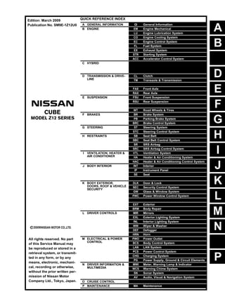
  • 1. A B D E F G H I J K L M N P O C QUICK REFERENCE INDEX A GENERAL INFORMATION GI General Information B ENGINE EM Engine Mechanical LU Engine Lubrication System CO Engine Cooling System EC Engine Control System FL Fuel System EX Exhaust System STR Starting System ACC Accelerator Control System C HYBRID HBB Hybrid Battery System HBR Hybrid Brake System D TRANSMISSION & DRIVE- LINE CL Clutch TM Transaxle & Transmission DLN Driveline FAX Front Axle RAX Rear Axle E SUSPENSION FSU Front Suspension RSU Rear Suspension SCS Suspension Control System WT Road Wheels & Tires F BRAKES BR Brake System PB Parking Brake System BRC Brake Control System G STEERING ST Steering System STC Steering Control System H RESTRAINTS SB Seat Belt SBC Seat Belt Control System SR SRS Airbag SRC SRS Airbag Control System I VENTILATION, HEATER & AIR CONDITIONER VTL Ventilation System HA Heater & Air Conditioning System HAC Heater & Air Conditioning Control System J BODY INTERIOR INT Interior IP Instrument Panel SE Seat ADP Automatic Drive Positioner K BODY EXTERIOR, DOORS, ROOF & VEHICLE SECURITY DLK Door & Lock SEC Security Control System GW Glass & Window System PWC Power Window Control System RF Roof EXT Exterior BRM Body Repair L DRIVER CONTROLS MIR Mirrors EXL Exterior Lighting System INL Interior Lighting System WW Wiper & Washer DEF Defogger HRN Horn M ELECTRICAL & POWER CONTROL PWO Power Outlet BCS Body Control System LAN LAN System PCS Power Control System CHG Charging System PG Power Supply, Ground & Circuit Elements N DRIVER INFORMATION & MULTIMEDIA MWI Meter, Warning Lamp & Indicator WCS Warning Chime System SN Sonar System AV Audio, Visual & Navigation System O CRUISE CONTROL CCS Cruise Control System P MAINTENANCE MA Maintenance All rights reserved. No part of this Service Manual may be reproduced or stored in a retrieval system, or transmit- ted in any form, or by any means, electronic, mechani- cal, recording or otherwise, without the prior written per- mission of Nissan Motor Company Ltd., Tokyo, Japan. Edition: March 2009 Publication No. SM9E-1Z12U0
  • 2. FOREWORD This manual contains maintenance and repair procedure for the 2009 NISSAN CUBE. In order to assure your safety and the efficient functioning of the vehicle, this manual should be read thoroughly. It is especially important that the PRECAUTIONS in the GI section be completely understood before starting any repair task. All information in this manual is based on the latest product information at the time of publication. The right is reserved to make changes in specifi- cations and methods at any time without notice. IMPORTANT SAFETY NOTICE The proper performance of service is essential for both the safety of the technician and the efficient functioning of the vehicle. The service methods in this Service Manual are described in such a manner that the service may be performed safely and accurately. Service varies with the procedures used, the skills of the technician and the tools and parts available. Accordingly, anyone using service procedures, tools or parts which are not specifically recommended by NISSAN must first be completely satisfied that neither personal safety nor the vehicle’s safety will be jeopardized by the service method selected.
  • 3. QUICK REFERENCE CHART CUBE QUICK REFERENCE CHART CUBE PFP:00000 ENGINE TUNE-UP DATA (MR18DE) ELS0003W Engine model MR18DE Firing order 1-3-4-2 Idle speed CVT (In “P or N” position) M/T (In Neutral position) rpm 700 ± 50 Ignition timing (BTDC at idle speed) 13° ± 5° CO% at idle 3 - 11 % and engine runs smoothly Tensions of drive belts Auto adjustment by auto tensioner Radiater cap relief pressure kPa (kg/cm2 , psi) Standard 78 - 98 (0.8 - 1.0, 11 - 14) Limit 59 (0.6, 9) Cooling system leakage testing pressure kPa (kg/cm2, psi) 156 (1.59, 22.6) Compression pressure kPa (kg/cm2 , psi)/250 rpm Standard 1,500 (15.3, 217.5) Minimum 1,200 (12.2, 174) Differential limit between cylinders 100 (1.0, 14.5) Spark plug (Iridium-tipped type) Make DENSO Standard type FXE20HR11 Gap (Nominal) mm (in) 1.1 (0.043) 2009
  • 4. QUICK REFERENCE CHART CUBE FRONT WHEEL ALIGNMENT ELS0003X Measure value under unladen* conditions. *: Fuel, engine coolant and lubricant are full. Spare tire, jack, hand tools and mats are in designated positions. REAR WHEEL ALIGNMENT ELS0003Y Measure value under unladen* conditions. *: Fuel, engine coolant and lubricant are full. Spare tire, jack, hand tools and mats are in designated positions. BRAKE PEDAL Unit: mm (in.) Camber Degree minute (Decimal degree) Minimum –0° 35′ (–0.58°) Nominal 0° 10′ (0.17°) Maximum 0° 55′ (0.91°) Left and right difference –0° 45′ (–0.75°) Caster Degree minute (Decimal degree) Minimum 3° 55′ (3.92°) Nominal 4° 40′ (4.67°) Maximum 5° 25′ (5.41°) Left and right difference –0° 45′ (–0.75°) Kingpin inclination Degree minute (Decimal degree) Minimum 9° 10′ (9.17°) Nominal 9° 55′ (9.92°) Maximum 13° 25′ (13.41°) Toe-in Total toe-in Distance Minimum 0 mm (0 in) Nominal In 1.0 mm (0.05 in) Maximum In 2.0 mm (0.07 in) Toe angle (left wheel or right wheel) Degree minute (Decimal degree) Minimum 0° 00′ (0.00°) Nominal In 0° 03′ (0.05°) Maximum In 0° 06′ (0.10°) Camber Degree minute (Decimal degree) Minimum –2° 00′ (–2.01°) Nominal –1° 31′ (–1.51°) Maximum –1° 01′ (–1.01°) Toe-in Total toe-in Distance Minimum Out 1.0 mm (Out 0.039 in) Nominal In 3.0 mm (In 0.118 in) Maximum In 7.0 mm (In 0.275 in) Toe angle (left wheel or right wheel) Degree minute (Decimal degree) Minimum Out 0° 02′ (Out 0.04°) Nominal In 0° 08′ (In 0.13°) Maximum In 0° 19′ (In 0.32°) Depressed brake pedal height (H1) M/T 162.3 - 172.3 (6.39 - 6.78) CVT 172.4 - 182.4 (6.79 - 7.18) Brake pedal reserve height (H2) [Depressing 490 N (50 kg, 110 lb) while turning the engine ON] M/T 80 (3.15) or more CVT 85 (3.35) or more 2009
  • 5. QUICK REFERENCE CHART CUBE FRONT DISK BRAKE Unit: mm (in.) REAR DRUM BRAKE Unit: mm (in.) REFILL CAPACITIES ELS00040 Item Limit Brake pad Wear thickness 2.0 (0.079) Disc rotor Wear thickness 22.0 (0.866) Item Limit Brake lining Wear thickness 1.5 (0.059) Brake drum Wear inner diameter 230.0 (9.06) UNIT Liter US measure Imp measure Fuel tank 50.0 13-1/4 gal 11 gal Engine Coolant (With reservoir tank) at MAX level CVT models 7.1 7-1/2 qt 6-1/4 qt M/T models 6.8 7-1/4 qt 6 qt Engine oil Drain and refill With oil filter change 4.1 4-2/8 qt 3-5/8 qt Without oil filter change 3.8 4 qt 3-3/8 qt Dry engine (Overhaul) 4.9 5-1/8 qt 4-3/8 qt Transmission CVT 7.4 7-7/8 qt 6-1/2 qt M/T 2 4-1/4 pt 3-1/2 pt Air conditioning system Compressor oil 0.12 4.1 fl oz 4.2 fl oz Refrigerant 0.45 kg 1.0 lb 1.0 lb 2009
  • 6. GI-1 GENERAL INFORMATION C D E F G H I J K L M B GI SECTION GI N O P CONTENTS GENERAL INFORMATION REGULAR GRADE HOW TO USE THIS MANUAL .................. .... 3 HOW TO USE THIS MANUAL ....................... ..... 3 Description .......................................................... ......3 Terms .................................................................. ......3 Units .................................................................... ......3 Contents .............................................................. ......3 Relation between Illustrations and Descriptions . ......4 Components ........................................................ ......4 HOW TO FOLLOW TROUBLE DIAGNOSES..... 6 Description .......................................................... ......6 How to Follow Test Groups in Trouble Diagnosis......6 Key to Symbols Signifying Measurements or Pro- cedures ............................................................... ......7 HOW TO READ WIRING DIAGRAMS ........... ..... 9 Connector Symbols ............................................. ......9 Sample/Wiring Diagram -Example- ..................... ....10 Description .......................................................... ....11 ABBREVIATIONS .......................................... ....13 Abbreviation List .................................................. ....13 TIGHTENING TORQUE OF STANDARD BOLTS ............................................................ ....14 Description .......................................................... ....14 Tightening Torque Table (New Standard Includ- ed) ....................................................................... ....14 RECOMMENDED CHEMICAL PRODUCTS AND SEALANTS ............................................ ....17 Recommended Chemical Products and Sealants ....17 VEHICLE INFORMATION ......................... ...18 IDENTIFICATION INFORMATION ................. ....18 Model Variation ................................................... ....18 Information About Identification or Model Code .. ....18 Dimensions ......................................................... ....20 Wheels & Tires .................................................... ....20 PRECAUTION ........................................... ...21 PRECAUTIONS .................................................21 Description ........................................................... ....21 Precaution for Supplemental Restraint System (SRS) "AIR BAG" and "SEAT BELT PRE-TEN- SIONER" ............................................................. ....21 Precaution Necessary for Steering Wheel Rota- tion after Battery Disconnect ............................... ....21 Precaution for Procedure without Cowl Top Cover ....22 General Precautions ............................................ ....22 Three Way Catalyst ............................................. ....23 Multiport Fuel Injection System or Engine Control System ................................................................. ....24 Hoses .................................................................. ....24 Engine Oils .......................................................... ....25 Air Conditioning ................................................... ....25 Fuel ...................................................................... ....25 LIFTING POINT .................................................26 Commercial Service Tools ................................... ....26 Garage Jack and Safety Stand and 2-Pole Lift ... ....26 Board-On Lift ....................................................... ....27 TOW TRUCK TOWING .....................................28 Tow Truck Towing ............................................... ....28 Vehicle Recovery (Freeing a Stuck Vehicle) ....... ....28 BASIC INSPECTION ................................ ...30 SERVICE INFORMATION FOR ELECTRICAL INCIDENT ..........................................................30 Work Flow ............................................................ ....30 Control Units and Electrical Parts ........................ ....30 How to Check Terminal ....................................... ....31 Intermittent Incident ............................................. ....34 Circuit Inspection ................................................. ....37 CONSULT-III/GST CHECKING SYSTEM .........42 Description ........................................................... ....42 Revision: 2009 March 2009 Z12
  • 7. GI-2 CONSULT-III Function and System Application*1... 42 CONSULT-III/GST Data Link Connector (DLC) Circuit .................................................................. ... 42 Wiring Diagram - CONSULT-III/GST CHECKING SYSTEM - ............................................................ ... 44 INSPECTION AND ADJUSTMENT ................ ... 47 ADDITIONAL SERVICE WHEN REMOVING BAT- TERY NEGATIVE TERMINAL ............................... ... 47 ADDITIONAL SERVICE WHEN REMOVING BATTERY NEGATIVE TERMINAL : Required Procedure After Battery Disconnection ............... ... 47 Krom VEHICLE INFORMATION .......................... 48 DIMENSIONS AND WEIGHTS ....................... ... 48 Dimensions and Weights ..................................... ... 48 PRECAUTION ............................................ 49 LIFTING POINT .............................................. ... 49 Lifting Point .......................................................... ... 49 TOW TRUCK TOWING .................................. ... 50 Tow Truck Towing ................................................ ... 50 Vehicle Recovery (Freeing a Stuck Vehicle) ........ ... 50 Revision: 2009 March 2009 Z12
  • 8. Thank you very much for your reading. Please Click Here Then Get More Information. NOTE: If there is no response to click on the link above, please download the PDF document first and then click on it.
  • 9. HOW TO USE THIS MANUAL GI-3 < HOW TO USE THIS MANUAL > [REGULAR GRADE] C D E F G H I J K L M B GI N O P HOW TO USE THIS MANUAL HOW TO USE THIS MANUAL Description INFOID:0000000004992449 This volume explains “Removal, Disassembly, Installation, Inspection and Adjustment” and “Trouble Diag- noses”. Terms INFOID:0000000004992450 • The captions WARNING and CAUTION warn you of steps that must be followed to prevent personal injury and/or damage to some part of the vehicle. WARNING indicates the possibility of personal injury if instructions are not followed. CAUTION indicates the possibility of component damage if instructions are not followed. BOLD TYPED STATEMENTS except WARNING and CAUTION give you helpful information. Standard value: Tolerance at inspection and adjustment. Limit value: The maximum or minimum limit value that should not be exceeded at inspection and adjust- ment. Units INFOID:0000000004992451 • The UNITS given in this manual are primarily expressed as the SI UNIT (International System of Unit), and alternatively expressed in the metric system and in the yard/pound system. Also with regard to tightening torque of bolts and nuts, there are descriptions both about range and about the standard tightening torque. “Example” Range Standard Contents INFOID:0000000004992452 • A QUICK REFERENCE INDEX, a black tab (e.g. ) is provided on the first page. You can quickly find the first page of each section by matching it to the section's black tab. • THE CONTENTS are listed on the first page of each section. • THE TITLE is indicated on the upper portion of each page and shows the part or system. • THE PAGE NUMBER of each section consists of two or three letters which designate the particular section and a number (e.g. “BR-5”). • THE SMALL ILLUSTRATIONS show the important steps such as inspection, use of special tools, knacks of work and hidden or tricky steps which are not shown in the previous large illustrations. Assembly, inspection and adjustment procedures for the complicated units such as the automatic transaxle or transmission, etc. are presented in a step-by-step format where necessary. Outer Socket Lock Nut : 59 - 78 N·m (6.0 - 8.0 kg-m, 43 - 58 ft-lb) Drive Shaft Installation Bolt : 44.3 N·m (4.5 kg-m, 33 ft-lb) Revision: 2009 March 2009 Z12
  • 10. GI-4 < HOW TO USE THIS MANUAL > [REGULAR GRADE] HOW TO USE THIS MANUAL Relation between Illustrations and Descriptions INFOID:0000000004992453 The following sample explains the relationship between the part description in an illustration, the part name in the text and the service procedures. Components INFOID:0000000004992454 • THE LARGE ILLUSTRATIONS are exploded views (see the following) and contain tightening torques, lubri- cation points, section number of the PARTS CATALOG (e.g. SEC. 440) and other information necessary to perform repairs. The illustrations should be used in reference to service matters only. When ordering parts, refer to the appro- priate PARTS CATALOG. Components shown in an illustration may be identified by a circled number. When this style of illustration is used, the text description of the components will follow the illustration. SAIA0519E Revision: 2009 March 2009 Z12
  • 11. HOW TO USE THIS MANUAL GI-5 < HOW TO USE THIS MANUAL > [REGULAR GRADE] C D E F G H I J K L M B GI N O P SYMBOLS 1. Union bolt 2. Copper washer 3. Brake hose 4. Cap 5. Bleed valve 6. Sliding pin bolt 7. Piston seal 8. Piston 9. Piston boot 10. Cylinder body 11. Sliding pin 12. Torque member mounting bolt 13. Washer 14. Sliding pin boot 15. Bushing 16. Torque member 17. Inner shim cover 18. Inner shim 19. Inner pad 20. Pad retainer 21. Pad wear sensor 22. Outer pad 23. Outer shim 24. Outer shim cover 1: PBC (Poly Butyl Cuprysil) grease or silicone-based grease 2: Rubber grease : Brake fluid Refer to GI section for additional symbol definitions. SFIA2959E SAIA0749E Revision: 2009 March 2009 Z12
  • 12. GI-6 < HOW TO USE THIS MANUAL > [REGULAR GRADE] HOW TO FOLLOW TROUBLE DIAGNOSES HOW TO FOLLOW TROUBLE DIAGNOSES Description INFOID:0000000004992455 NOTICE: Trouble diagnoses indicate work procedures required to diagnose problems effectively. Observe the following instructions before diagnosing. • Before performing trouble diagnoses, read the “Work Flow” in each section. • After repairs, re-check that the problem has been completely eliminated. • Refer to Component Parts and Harness Connector Location for the Systems described in each section for identification/location of components and harness connectors. • When checking circuit continuity, ignition switch should be OFF. • Refer to the Circuit Diagram for quick pinpoint check. If you need to check circuit continuity between harness connectors in more detail, such as when a sub-har- ness is used, refer to Wiring Diagram in each individual section and Harness Layout in PG section for identi- fication of harness connectors. • Before checking voltage at connectors, check battery voltage. • After accomplishing the Diagnosis Procedures and Electrical Components Inspection, check that all harness connectors are reconnected as they were. How to Follow Test Groups in Trouble Diagnosis INFOID:0000000004992456 1. Test group number and test group title • Test group number and test group title are shown in the upper portion of each test group. 2. Work and diagnosis procedure • Start to diagnose a problem using procedures indicated in enclosed test groups. 3. Questions and results • Questions and required results are indicated in test group. 4. Action • Next action for each test group is indicated based on result of each question. JPAIA0021GB Revision: 2009 March 2009 Z12
  • 13. HOW TO FOLLOW TROUBLE DIAGNOSES GI-7 < HOW TO USE THIS MANUAL > [REGULAR GRADE] C D E F G H I J K L M B GI N O P Key to Symbols Signifying Measurements or Procedures INFOID:0000000004992457 JPAIA0397GB Revision: 2009 March 2009 Z12