SlideShare a Scribd company logo
1 of 14
Download to read offline
1998-99 ENGINES
2.4L 4-Cylinder
ENGINE IDENTIFICATION
Vehicle Identification Number (VIN) is stamped on a metal tab, attached to top left end of instrument panel,
near the windshield. Engine can also be identified by an engine code (3rd character) stamped on left side of
cylinder block. See Fig. 1 . See the ENGINE IDENTIFICATION CODES table.
ENGINE IDENTIFICATION CODES
Fig. 1: Locating Partial VIN & Engine Code
Courtesy of GENERAL MOTORS CORP.
ADJUSTMENTS
VALVE CLEARANCE ADJUSTMENT
NOTE: For repair procedures not covered in this article, see ENGINE OVERHAUL
PROCEDURES article in GENERAL INFORMATION.
Application VIN Code Engine ID
2.4L DOHC SFI T LD9
1999 Pontiac Grand Am GT
1998-99 ENGINES 2.4L 4-Cylinder
1999 Pontiac Grand Am GT
1998-99 ENGINES 2.4L 4-Cylinder
me
Wednesday, May 20, 2009 9:20:38 AM Page 1 © 2005 Mitchell Repair Information Company, LLC.
me
Wednesday, May 20, 2009 9:21:20 AM Page 1 © 2005 Mitchell Repair Information Company, LLC.
Engine is equipped with non-adjustable hydraulic valve lifters.
TROUBLE SHOOTING
REMOVAL & INSTALLATION
FUEL PRESSURE RELEASE
Disconnect negative battery cable. Loosen fuel filler cap. Install Fuel Pressure Gauge (J-34730-1) on fuel
pressure connector of fuel rail. Wrap shop towel around pressure connection when installing fuel pressure gauge
to absorb fuel leakage. Install gauge bleed hose into container. Open bleed valve to bleed fuel pressure.
COOLING SYSTEM BLEEDING
1. Fill radiator and surge tank to base of filler neck. Install pressure cap on surge tank. Block drive wheels
and firmly apply parking brake. Shift automatic transaxle to Park or manual transaxle to Neutral. Start
engine. Run until upper radiator hose is hot. Stop engine.
2. Observe coolant level in surge tank or radiator. If not above FULL mark, allow engine to cool and then
remove surge tank cap. Add coolant. If low coolant light lights after servicing, remove surge tank cap and
add coolant to bring level to COLD FULL mark when system is cold.
ENGINE
Removal (1998 Models)
1. Release fuel pressure. See FUEL PRESSURE RELEASE . Disconnect negative battery cable. Drain
cooling system. Discharge air conditioning system (if equipped) using approved refrigerant
NOTE: To trouble shoot mechanical engine components, see ENGINE MECHANICAL in
GENERAL TROUBLE SHOOTING article in GENERAL INFORMATION.
CAUTION: When battery is disconnected, vehicle computer and memory systems
may lose memory data. Driveability problems may exist until computer
systems have completed a relearn cycle. For 1998, see appropriate model
under COMPUTER RELEARN PROCEDURES in COMPUTER RELEARN
PROCEDURES article in GENERAL INFORMATION. For 1999, See
appropriate model in COMPUTER RELEARN PROCEDURES article in
GENERAL INFORMATION.
NOTE: For reassembly reference, label all electrical connectors, vacuum hoses and
fuel lines before removal. Also place mating marks on engine hood and other
major assemblies before removal.
NOTE: On 1998 models, remove engine and transaxle as an assembly through bottom
of engine compartment.
1999 Pontiac Grand Am GT
1998-99 ENGINES 2.4L 4-Cylinder
me
Wednesday, May 20, 2009 9:20:38 AM Page 2 © 2005 Mitchell Repair Information Company, LLC.
recovery/recycling equipment.
2. Remove left sound insulator and disconnect push rod from clutch pedal assembly (if equipped).
Disconnect control cables, coolant hoses, electrical connectors, vacuum hoses, and fuel lines as necessary.
Remove air cleaner assembly. Remove cooling fan. Disconnect air conditioning hose assembly from
compressor (if equipped). Discard "O" rings.
3. Remove throttle cable and bracket. Remove power steering pump bolts and pump (leave hoses
connected). Disconnect shift cables. Disconnect clutch actuator (slave cylinder) hydraulic line. Remove
exhaust manifold and heat shield. See EXHAUST MANIFOLD .
4. Support engine from above with Engine Support Fixture (J-28467-A). Remove coolant recovery tank
(leave hoses connected) and position aside. Remove engine mount from timing chain end of engine. Raise
and support vehicle. Remove front wheels. Remove right splash shield. Remove engine mount strut and
transaxle mount. Separate ball joints from steering knuckles.
5. Put a suitable supporting device under suspension support, crossmember and stabilizer shaft. Remove
suspension support and stabilizer shaft. Remove heater outlet hose from radiator outlet pipe. Remove axle
shaft from transaxle and intermediate shaft (manual transaxle only) and position aside.
6. Remove flywheel housing cover. Put a suitable supporting device under engine and transaxle assembly
and lower vehicle onto support. Mark threads on engine upper support fixture hooks for installation
reference. Remove engine upper support fixture hooks. Raise vehicle slowly from engine and transaxle
assembly. Separate engine from transaxle (note bolt location for reassembly reference).
Installation
1. Assemble engine to transaxle, ensuring bolts are in correct locations. On automatic transaxle models,
clean torque converter bolts and bolt holes. Apply sealant to bolts. On all models, position engine and
transaxle assembly under engine compartment. Lower vehicle until transaxle mount is aligned. Install
transaxle mount bolt.
2. Install Engine Support Fixture (J-28467-A) above engine, adjusting it to previous setting. Install engine
mount at timing chain end of engine. Install engine mount at transaxle. Raise vehicle. Remove supporting
device from below engine and transaxle assembly. Install axle shafts.
3. Install suspension support, crossmember and stabilizer shaft assembly. Tighten suspension support rear
bolts, center bolts and then front bolts to specification. See TORQUE SPECIFICATIONS table.
Connect ball joints. Install engine mount strut. To complete installation, reverse removal procedure.
Evacuate and charge air conditioning system. Fill cooling system and crankcase.
Removal (1999 Models)
1. Release fuel pressure. See FUEL PRESSURE RELEASE . Disconnect negative battery cable. Drain
cooling system and engine oil. Remove fuel rail assembly, air intake duct from air cleaner, ignition coil
and module assembly. Disconnect control cables, coolant hoses, electrical connectors, vacuum hoses, and
fuel lines as necessary.
2. Unbolt power steering pump and secure aside. Remove air intake duct bracket. Remove cruise control
assembly and set aside. Install J 28467-360 engine support fixture. Remove fan belt and engine mount
assembly. Raise engine using support fixture, then remove engine mount bracket.
NOTE: On 1999 models, remove engine while leaving transmission in vehicle.
1999 Pontiac Grand Am GT
1998-99 ENGINES 2.4L 4-Cylinder
me
Wednesday, May 20, 2009 9:20:38 AM Page 3 © 2005 Mitchell Repair Information Company, LLC.
3. Raise and support vehicle. Remove front wheels and right splash shield. Remove crankshaft balancer.
Remove torque converter bolts and oxygen sensor. Lower vehicle. Remove generator and starter. Remove
exhaust brace bolt and exhaust manifold heat shield. Disconnect exhaust pipe from exhaust manifold.
4. Unbolt A/C compressor and secure aside. Remove oil pan-to-bellhousing bolts. Remove transmission
mount. Remove transmission-to-engine bolts. Install engine hoist, then remove engine while supporting
transaxle.
Installation
To install, reverse removal procedure. Tighten all fasteners to specifications. See TORQUE
SPECIFICATIONS table. Fill engine fluids, and bleed cooling system. See COOLING SYSTEM
BLEEDING .
INTAKE MANIFOLD
Removal
1. Disconnect negative battery cable. Disconnect electrical connectors and vacuum hoses from intake
manifold components as necessary. Disconnect air intake tube. Remove throttle cable bracket.
2. Remove generator mount bolt. Remove EGR pipe from EGR adapter. Remove intake manifold nuts and
bolts. Remove intake manifold and gasket.
Installation
Tighten all intake manifold nuts and bolts to specification in sequence. See Fig. 2 . See TORQUE
SPECIFICATIONS table. To complete installation, reverse removal procedure.
WARNING: Never remove intake manifold while engine is hot. Intake manifold is
made of composite plastic and can be damaged if removed while engine
is hot.
NOTE: Intake manifold gasket is reusable unless damaged. Numbered side of intake
manifold gasket must face intake manifold.
1999 Pontiac Grand Am GT
1998-99 ENGINES 2.4L 4-Cylinder
me
Wednesday, May 20, 2009 9:20:38 AM Page 4 © 2005 Mitchell Repair Information Company, LLC.
Fig. 2: Intake Manifold Tightening Sequence
Courtesy of GENERAL MOTORS CORP.
EXHAUST MANIFOLD
Removal
1. Disconnect negative battery cable. Disconnect oxygen sensor connector. Raise and support vehicle.
Remove exhaust manifold brace bolt. Remove upper heat shield. Disconnect exhaust pipe flex decoupler
from manifold. DO NOT allow flex decoupler to bend more than 3 degrees in any direction, as damage
will result.
2. Pull down and back on exhaust pipe to disengage it from manifold. Lower vehicle. Remove exhaust
manifold nuts. Remove exhaust manifold, seals and gaskets.
Installation
To install, reverse removal procedure using NEW gaskets. Tighten bolts to specification in sequence. See
TORQUE SPECIFICATIONS table. See Fig. 3 . If oxygen sensor was removed, coat threads with Anti-Seize
Compound (5612695) before installation.
1999 Pontiac Grand Am GT
1998-99 ENGINES 2.4L 4-Cylinder
me
Wednesday, May 20, 2009 9:20:39 AM Page 5 © 2005 Mitchell Repair Information Company, LLC.
Fig. 3: Exhaust Manifold Tightening Sequence
Courtesy of GENERAL MOTORS CORP.
CYLINDER HEAD
Removal
1. Disconnect negative battery cable. Drain cooling system. Remove throttle body-to-air cleaner duct.
Disconnect heater hose and throttle body hose from water outlet. Remove power brake vacuum hose from
throttle body.
2. Disconnect electrical connectors, vacuum hoses, and coolant hoses as necessary. Remove generator
mount bolt. Remove intake manifold. See INTAKE MANIFOLD . Remove generator mount bolt.
3. Reinstall generator mount bolt. Install Engine Support Fixtures (J-28467-400 and J-28467-A). Remove
exhaust manifold. See EXHAUST MANIFOLD . Remove ignition coil and module assembly
connectors. Remove attaching bolts and remove coil assembly from camshaft housing by pulling it
straight up. See Fig. 12 .
4. Disconnect camshaft position sensor connector. Remove power steering pump. Remove fuel line
retaining clamp from bracket on top of intake camshaft housing. Remove fuel rail from cylinder head, and
leaving fuel lines attached, position on top of master cylinder. Cover injector openings in head and
injector nozzles.
5. Remove timing chain and sprocket. See TIMING CHAIN, SPROCKETS & TENSIONER .
CAUTION: Turn camshaft housing upside down immediately after removing
from vehicle, or valve lifters will fall out and may be damaged.
1999 Pontiac Grand Am GT
1998-99 ENGINES 2.4L 4-Cylinder
me
Wednesday, May 20, 2009 9:20:39 AM Page 6 © 2005 Mitchell Repair Information Company, LLC.
Disconnect timing chain housing at intake camshaft housing but DO NOT remove from vehicle. Remove
bolts attaching intake camshaft housing to cylinder head bolts in reverse of tightening sequence. See Fig.
13 . Remove camshaft housing. Repeat procedure with exhaust camshaft housing.
6. Disconnect radiator inlet hose from coolant outlet and disconnect coolant temperature sensor connectors.
Remove cylinder head bolts in reverse order of tightening sequence. See Fig. 4 . Remove cylinder head
and gasket. See CYLINDER HEAD under OVERHAUL.
Installation
Clean threads of cylinder head bolts and bolt holes. Lightly coat bolt threads with engine oil. Install NEW
gasket, ensuring all holes are aligned with cylinder block. Install cylinder head and tighten cylinder head bolts
to specification in sequence. See TORQUE SPECIFICATIONS table. To complete installation, reverse
removal procedure. See Fig. 4 .
Fig. 4: Cylinder Head Bolt Tightening Sequence
Courtesy of GENERAL MOTORS CORP.
FRONT COVER
CAUTION: DO NOT use a thread tap to clean cylinder head bolt holes. Remove all
fluids from bolt holes.
1999 Pontiac Grand Am GT
1998-99 ENGINES 2.4L 4-Cylinder
me
Wednesday, May 20, 2009 9:20:39 AM Page 7 © 2005 Mitchell Repair Information Company, LLC.
Removal
1. Disconnect negative battery cable. Drain cooling system. Remove coolant recovery tank. Remove
serpentine drive belt. Remove generator (leave wiring attached). Attach Engine Support Fixture (J-28467-
400 and J-28467-A) to engine and generator stud. Remove bolts from upper half of front cover.
2. Remove engine mount assembly from timing chain end of engine. Remove engine mounting bracket
adapter. Raise and support vehicle. Remove right front wheel and splash shield. Remove crankshaft
balancer bolt. Remove crankshaft balancer with a puller. Remove lower bolts from front cover. Lower
vehicle. Remove front cover and gaskets.
Installation
To install, reverse removal procedure. Cover gasket is reusable if not damaged. Lubricate front seal with grease
before installing crankshaft balancer. To complete installation, reverse removal procedure. Tighten nuts and
bolts to specification. See TORQUE SPECIFICATIONS table. Fill cooling system.
CRANKSHAFT FRONT SEAL
Removal & Installation
Disconnect negative battery cable. Remove front cover. See FRONT COVER . Support cover, and drive seal
through rear of cover. Take care not to damage cover. Note direction of seal installation. To install seal, use
Seal Installer (J-36010).
TIMING CHAIN, SPROCKETS & TENSIONER
Removal
1. Disconnect negative battery cable. Remove front cover. See FRONT COVER . See Fig. 5 . Rotate
crankshaft in normal direction of rotation (clockwise, as viewed from front of engine) until cylinder No. 1
is at TDC of compression stroke.
2. The camshaft sprocket dowel pin hole should line up with holes on timing chain housing. The crankshaft
sprocket keyway should point upwards. See Fig. 5 . Remove timing chain guides. Raise and support
vehicle. Ensure slack in chain is above tensioner assembly, then remove chain tensioner.
3. Note that timing chain must be disengaged from any wear grooves in tensioner shoe before removing
shoe. Slide a screwdriver blade between chain and tensioner shoe, while pulling shoe outward (this
should disengage chain from wear grooves in shoe). If timing chain is not difficult to remove, go to step
5 . If it is difficult to remove timing chain shoe, go to next step.
NOTE: This procedure has been revised due to GM service manual update (SMU) # 00-
06-01-002 dated Feb, 2000
CAUTION: To prevent severe engine damage, carefully follow procedure.
1999 Pontiac Grand Am GT
1998-99 ENGINES 2.4L 4-Cylinder
me
Wednesday, May 20, 2009 9:20:39 AM Page 8 © 2005 Mitchell Repair Information Company, LLC.
Thank you very much for
your reading. Please Click
Here. Then Get COMPLETE
MANUAL. NO WAITING
NOTE:
If there is no response to
click on the link above,
please download the PDF
document first and then
click on it.
4. Lower vehicle. Hold intake camshaft sprocket with Sprocket Wrench (J-39579) and remove sprocket bolt.
Remove washer from bolt and rethread bolt into camshaft by hand. Remove camshaft sprocket using a 3-
jaw puller. DO NOT attempt to pry sprocket off or damage will result.
5. Remove tensioner assembly bolts and tensioner. Mark outer surface of timing chain and crankshaft
sprocket for reassembly reference. Remove timing chain.
Fig. 5: Assembled View Of Timing Chain, Sprockets & Tensioner
Courtesy of GENERAL MOTORS CORP.
Installation
CAUTION: To prevent damage to sprocket or timing chain housing, use a puller
to remove sprocket from camshaft. DO NOT pry sprocket from
camshaft.
1999 Pontiac Grand Am GT
1998-99 ENGINES 2.4L 4-Cylinder
me
Wednesday, May 20, 2009 9:20:39 AM Page 9 © 2005 Mitchell Repair Information Company, LLC.
1. Install the camshaft sprockets. The sprockets are identical and interchangeable. Clean the old sealer off of
the bolts with a wire brush. Clean the threaded hole in the camshaft with a nylon bristle brush. Coat the
camshaft bolts with Adhesive/Sealant Compound (GM 1234593) or equivalent. See Fig. 6 .
2. Install the camshaft sprocket bolts and washers while holding the sprockets with Tool (J- 39579). Tighten
the bolts to 52 ft. lbs. (70 N.m).
3. Install Tool (J-36008-A) through the holes in the camshaft sprockets and into the holes in the timing
chain housing. This will position the camshaft for correct timing. Use the following steps if the camshafts
are out of position and must be rotated more than 1/8 turn in order to install the alignment dowel pins:
A. The crankshaft must be rotated 90 degrees clockwise from TDC to give the valves adequate
clearance to open.
B. Once the camshafts are in position and the dowels are installed, rotate the crankshaft counter
clockwise back to TDC.
4. Install the timing chain over the exhaust camshaft sprocket around the coolant pump sprocket and around
the crankshaft sprocket. Remove the alignment dowel pin from the intake camshaft. Use Tool (J-39579)
in order to rotate the intake camshaft sprocket counter clockwise enough to allow the timing chain to slide
over the intake camshaft sprocket. Release Tool (J-39579). The length of the chain between the two
camshaft sprockets will tighten.
5. If properly timed, the intake camshaft alignment dowel pin will slide in easily. If the dowel pin does not
fully index, the camshafts are not timed correctly and the procedure must be repeated. Leave the
alignment dowel pins installed. The keyway on the crankshaft and the mark on the cylinder block should
be aligned when the slack is removed from the chain between the intake camshaft sprocket and the
crankshaft sprocket. If the mark and the keyway are not aligned, move the chain one tooth forward or
rearward. Remove the slack and recheck the marks.
NOTE: Ensure camshaft sprocket alignment pins are in the cylinder block and the
timing chain housing, prior to installing the timing chain housing. The
camshaft sprocket alignment pins ensure proper chain housing and front
cover location for correct front oil seal to crankshaft alignment.
CAUTION: DO NOT rotate the crankshaft clockwise to TDC. Valve or piston
damage could occur. The timing chain and crankshaft sprocket must
be put in a specific direction for chain noise and wear
considerations. The surfaces that were marked during removal
should be showing when the chain and crankshaft sprocket are
installed.
NOTE: Use the following steps in order to reset the timing chain tensioner
assembly to the zero position:
A. Reset the timing chain tensioner assembly.
B. Insert the tensioner plunger assembly into the tensioner housing.
C. With the tensioner plunger fully extended, turn the complete
1999 Pontiac Grand Am GT
1998-99 ENGINES 2.4L 4-Cylinder
me
Wednesday, May 20, 2009 9:20:39 AM Page 10 © 2005 Mitchell Repair Information Company, LLC.
6. Check the plunger to ensure the plunger is out of the cylinder at the correct dimension. The correct
dimension for the plunger to extend out of the cylinder is .070" (1.7 mm) maximum. See Fig. 8 . Loosely
install the tensioner assembly and bolts to the timing chain housing. See Fig. 9 . Install the timing chain
tensioner shoe on the stud. Apply hand pressure to the timing chain tensioner shoe until the locking tab
seats in the groove in the stud. Tighten the timing chain tensioner bolts. DO NOT over tighten. Tighten
the bolts to 89 INCH lbs. (10 N.m).
7. Release the timing chain tensioner plunger using the following procedure:
A. Using a flat blade screwdriver, cotter pin remover, or a similar tool, press firmly against the face of
the timing chain tensioner plunger. See Fig. 10 .
B. Depress the timing chain tensioner plunger until the plunger is bottomed out in the bore of the
timing chain tensioner. See Fig. 8 .
C. Release the tensioner plunger. See Fig. 10 . The plunger should press firmly against the back of the
timing chain tensioner shoe. Remove Tool (J- 36008-A) from the camshaft sprockets.
8. Rotate the crankshaft clockwise two full rotations. Align the crankshaft keyway with the mark on the
cylinder block and reinstall the alignment dowel pins. The alignment dowel pins will slide in easily if the
engine is timed correctly. Install the timing chain guides.
assembly upside down on a bench or other flat surface. See Fig. 7 .
D. With the plunger face against the workbench, press firmly on the
bottom of the tensioner housing.
E. Compress the plunger until the plunger is seated flush in the
tensioner. See Fig. 8 .
CAUTION: If the timing chain tensioner plunger is not released from the
installation position, engine damage will occur when the engine is
started.
NOTE: If the timing chain tensioner plunger cannot be depressed, the
plunger is not properly reset and the procedure for resetting the
timing chain tensioner should be repeated.
CAUTION: Beginning with the 1998 model year, the timing chain on the LD9 (VIN
T) Twin Cam Engine is different from the chain found on earlier
versions of this engine, and is not to be replaced with a timing chain
from earlier model year engines. The timing sprockets were also
changed beginning in 1998, and the shape of the chain links matches
the sprockets. Engine damage may result if the wrong timing chain is
used. The timing chain and the crankshaft sprocket must be marked
so that they are reinstalled in the same side facing out at the time of
assembly.
1999 Pontiac Grand Am GT
1998-99 ENGINES 2.4L 4-Cylinder
me
Wednesday, May 20, 2009 9:20:39 AM Page 11 © 2005 Mitchell Repair Information Company, LLC.
Fig. 6: Installing Timing Chain Sprockets
Courtesy of GENERAL MOTORS CORP.
1999 Pontiac Grand Am GT
1998-99 ENGINES 2.4L 4-Cylinder
me
Wednesday, May 20, 2009 9:20:39 AM Page 12 © 2005 Mitchell Repair Information Company, LLC.
Fig. 7: Released View Of Timing Chain Tensioner Assembly
Courtesy of GENERAL MOTORS CORP.
1999 Pontiac Grand Am GT
1998-99 ENGINES 2.4L 4-Cylinder
me
Wednesday, May 20, 2009 9:20:39 AM Page 13 © 2005 Mitchell Repair Information Company, LLC.

More Related Content

What's hot

Hyster c098 (e80 xl3) forklift service repair manual
Hyster c098 (e80 xl3) forklift service repair manualHyster c098 (e80 xl3) forklift service repair manual
Hyster c098 (e80 xl3) forklift service repair manualjfjkskekfsmem
 
Hyster e098 (e4.00 xl europe) forklift service repair manual
Hyster e098 (e4.00 xl europe) forklift service repair manualHyster e098 (e4.00 xl europe) forklift service repair manual
Hyster e098 (e4.00 xl europe) forklift service repair manualdkddmdd
 
Hyster b187 (s50 xl) forklift service repair manual
Hyster b187 (s50 xl) forklift service repair manualHyster b187 (s50 xl) forklift service repair manual
Hyster b187 (s50 xl) forklift service repair manualuujfjjskkdme
 
Hyster c108 (e3.00 xl europe) forklift service repair manual
Hyster c108 (e3.00 xl europe) forklift service repair manualHyster c108 (e3.00 xl europe) forklift service repair manual
Hyster c108 (e3.00 xl europe) forklift service repair manualfujdfjjjsekkemme
 
5sfe engine removal
5sfe engine removal5sfe engine removal
5sfe engine removalarnierider
 
Hyster g108 (e60 z) forklift service repair manual
Hyster g108 (e60 z) forklift service repair manualHyster g108 (e60 z) forklift service repair manual
Hyster g108 (e60 z) forklift service repair manualfjsekqazxkdmmem
 
YALE (C910) GLC050VX LIFT TRUCK Service Repair Manual
YALE (C910) GLC050VX LIFT TRUCK Service Repair ManualYALE (C910) GLC050VX LIFT TRUCK Service Repair Manual
YALE (C910) GLC050VX LIFT TRUCK Service Repair Manualfujfdjjskfkemd
 
YALE F818 GLC55SVX LIFT TRUCK (EUROPE) Service Repair Manual
YALE F818 GLC55SVX LIFT TRUCK (EUROPE) Service Repair ManualYALE F818 GLC55SVX LIFT TRUCK (EUROPE) Service Repair Manual
YALE F818 GLC55SVX LIFT TRUCK (EUROPE) Service Repair Manualyehnmdm jnkmem
 
Case ih case international 5120 tractor service repair manual
Case ih case international 5120 tractor service repair manualCase ih case international 5120 tractor service repair manual
Case ih case international 5120 tractor service repair manualfjjsieskekfmmse
 

What's hot (9)

Hyster c098 (e80 xl3) forklift service repair manual
Hyster c098 (e80 xl3) forklift service repair manualHyster c098 (e80 xl3) forklift service repair manual
Hyster c098 (e80 xl3) forklift service repair manual
 
Hyster e098 (e4.00 xl europe) forklift service repair manual
Hyster e098 (e4.00 xl europe) forklift service repair manualHyster e098 (e4.00 xl europe) forklift service repair manual
Hyster e098 (e4.00 xl europe) forklift service repair manual
 
Hyster b187 (s50 xl) forklift service repair manual
Hyster b187 (s50 xl) forklift service repair manualHyster b187 (s50 xl) forklift service repair manual
Hyster b187 (s50 xl) forklift service repair manual
 
Hyster c108 (e3.00 xl europe) forklift service repair manual
Hyster c108 (e3.00 xl europe) forklift service repair manualHyster c108 (e3.00 xl europe) forklift service repair manual
Hyster c108 (e3.00 xl europe) forklift service repair manual
 
5sfe engine removal
5sfe engine removal5sfe engine removal
5sfe engine removal
 
Hyster g108 (e60 z) forklift service repair manual
Hyster g108 (e60 z) forklift service repair manualHyster g108 (e60 z) forklift service repair manual
Hyster g108 (e60 z) forklift service repair manual
 
YALE (C910) GLC050VX LIFT TRUCK Service Repair Manual
YALE (C910) GLC050VX LIFT TRUCK Service Repair ManualYALE (C910) GLC050VX LIFT TRUCK Service Repair Manual
YALE (C910) GLC050VX LIFT TRUCK Service Repair Manual
 
YALE F818 GLC55SVX LIFT TRUCK (EUROPE) Service Repair Manual
YALE F818 GLC55SVX LIFT TRUCK (EUROPE) Service Repair ManualYALE F818 GLC55SVX LIFT TRUCK (EUROPE) Service Repair Manual
YALE F818 GLC55SVX LIFT TRUCK (EUROPE) Service Repair Manual
 
Case ih case international 5120 tractor service repair manual
Case ih case international 5120 tractor service repair manualCase ih case international 5120 tractor service repair manual
Case ih case international 5120 tractor service repair manual
 

Similar to 2000 pontiac grand am service repair manual

2002 toyota corolla service repair manual
2002 toyota corolla service repair manual2002 toyota corolla service repair manual
2002 toyota corolla service repair manualjknsmmem
 
2000 toyota corolla service repair manual
2000 toyota corolla service repair manual2000 toyota corolla service repair manual
2000 toyota corolla service repair manualjkmsedopl
 
1999 toyota corolla service repair manual
1999 toyota corolla service repair manual1999 toyota corolla service repair manual
1999 toyota corolla service repair manualfujjsefkksemmm
 
2002 TOYOTA COROLLA Service Repair Manual
2002 TOYOTA COROLLA Service Repair Manual2002 TOYOTA COROLLA Service Repair Manual
2002 TOYOTA COROLLA Service Repair Manualjnsekmdmm
 
2001 toyota corolla service repair manual
2001 toyota corolla service repair manual2001 toyota corolla service repair manual
2001 toyota corolla service repair manualjksnmdms
 
2001 TOYOTA COROLLA Service Repair Manual
2001 TOYOTA COROLLA Service Repair Manual2001 TOYOTA COROLLA Service Repair Manual
2001 TOYOTA COROLLA Service Repair Manualjkndhjsnhd
 
1998 toyota avalon service repair manual
1998 toyota avalon service repair manual1998 toyota avalon service repair manual
1998 toyota avalon service repair manualfujjsefkksemmm
 
Volvo G990 Motor Grader Service Repair Manual Instant Download.pdf
Volvo G990 Motor Grader Service Repair Manual Instant Download.pdfVolvo G990 Motor Grader Service Repair Manual Instant Download.pdf
Volvo G990 Motor Grader Service Repair Manual Instant Download.pdffijsekkkdmdm3e
 
Volvo G990 Motor Grader Service Repair Manual Instant Download.pdf
Volvo G990 Motor Grader Service Repair Manual Instant Download.pdfVolvo G990 Motor Grader Service Repair Manual Instant Download.pdf
Volvo G990 Motor Grader Service Repair Manual Instant Download.pdflunrizan628
 
Volvo G990 Motor Grader Service Repair Manual Instant Download.pdf
Volvo G990 Motor Grader Service Repair Manual Instant Download.pdfVolvo G990 Motor Grader Service Repair Manual Instant Download.pdf
Volvo G990 Motor Grader Service Repair Manual Instant Download.pdffapanhe306271
 
Volvo G990 Motor Grader Service Repair Manual Instant Download.pdf
Volvo G990 Motor Grader Service Repair Manual Instant Download.pdfVolvo G990 Motor Grader Service Repair Manual Instant Download.pdf
Volvo G990 Motor Grader Service Repair Manual Instant Download.pdff8iosedkdm3e
 
Volvo G990 Motor Grader Service Repair Manual Instant Download.pdf
Volvo G990 Motor Grader Service Repair Manual Instant Download.pdfVolvo G990 Motor Grader Service Repair Manual Instant Download.pdf
Volvo G990 Motor Grader Service Repair Manual Instant Download.pdfrou774513po
 
Volvo G990 Motor Grader Service Repair Manual Instant Download.pdf
Volvo G990 Motor Grader Service Repair Manual Instant Download.pdfVolvo G990 Motor Grader Service Repair Manual Instant Download.pdf
Volvo G990 Motor Grader Service Repair Manual Instant Download.pdfzhenchun51
 
Volvo G976 Motor Grader Service Repair Manual Instant Download.pdf
Volvo G976 Motor Grader Service Repair Manual Instant Download.pdfVolvo G976 Motor Grader Service Repair Manual Instant Download.pdf
Volvo G976 Motor Grader Service Repair Manual Instant Download.pdffijsekkkdmdm3e
 
Volvo G976 Motor Grader Service Repair Manual Instant Download.pdf
Volvo G976 Motor Grader Service Repair Manual Instant Download.pdfVolvo G976 Motor Grader Service Repair Manual Instant Download.pdf
Volvo G976 Motor Grader Service Repair Manual Instant Download.pdffapanhe306271
 
Volvo G976 Motor Grader Service Repair Manual Instant Download.pdf
Volvo G976 Motor Grader Service Repair Manual Instant Download.pdfVolvo G976 Motor Grader Service Repair Manual Instant Download.pdf
Volvo G976 Motor Grader Service Repair Manual Instant Download.pdff8iosedkdm3e
 
Volvo G976 Motor Grader Service Repair Manual Instant Download.pdf
Volvo G976 Motor Grader Service Repair Manual Instant Download.pdfVolvo G976 Motor Grader Service Repair Manual Instant Download.pdf
Volvo G976 Motor Grader Service Repair Manual Instant Download.pdfrou774513po
 
Volvo G976 Motor Grader Service Repair Manual Instant Download.pdf
Volvo G976 Motor Grader Service Repair Manual Instant Download.pdfVolvo G976 Motor Grader Service Repair Manual Instant Download.pdf
Volvo G976 Motor Grader Service Repair Manual Instant Download.pdfzhenchun51
 
Volvo G970 Motor Grader Service Repair Manual Instant Download.pdf
Volvo G970 Motor Grader Service Repair Manual Instant Download.pdfVolvo G970 Motor Grader Service Repair Manual Instant Download.pdf
Volvo G970 Motor Grader Service Repair Manual Instant Download.pdffijsekkkdmdm3e
 
Volvo G970 Motor Grader Service Repair Manual Instant Download.pdf
Volvo G970 Motor Grader Service Repair Manual Instant Download.pdfVolvo G970 Motor Grader Service Repair Manual Instant Download.pdf
Volvo G970 Motor Grader Service Repair Manual Instant Download.pdflunrizan628
 

Similar to 2000 pontiac grand am service repair manual (20)

2002 toyota corolla service repair manual
2002 toyota corolla service repair manual2002 toyota corolla service repair manual
2002 toyota corolla service repair manual
 
2000 toyota corolla service repair manual
2000 toyota corolla service repair manual2000 toyota corolla service repair manual
2000 toyota corolla service repair manual
 
1999 toyota corolla service repair manual
1999 toyota corolla service repair manual1999 toyota corolla service repair manual
1999 toyota corolla service repair manual
 
2002 TOYOTA COROLLA Service Repair Manual
2002 TOYOTA COROLLA Service Repair Manual2002 TOYOTA COROLLA Service Repair Manual
2002 TOYOTA COROLLA Service Repair Manual
 
2001 toyota corolla service repair manual
2001 toyota corolla service repair manual2001 toyota corolla service repair manual
2001 toyota corolla service repair manual
 
2001 TOYOTA COROLLA Service Repair Manual
2001 TOYOTA COROLLA Service Repair Manual2001 TOYOTA COROLLA Service Repair Manual
2001 TOYOTA COROLLA Service Repair Manual
 
1998 toyota avalon service repair manual
1998 toyota avalon service repair manual1998 toyota avalon service repair manual
1998 toyota avalon service repair manual
 
Volvo G990 Motor Grader Service Repair Manual Instant Download.pdf
Volvo G990 Motor Grader Service Repair Manual Instant Download.pdfVolvo G990 Motor Grader Service Repair Manual Instant Download.pdf
Volvo G990 Motor Grader Service Repair Manual Instant Download.pdf
 
Volvo G990 Motor Grader Service Repair Manual Instant Download.pdf
Volvo G990 Motor Grader Service Repair Manual Instant Download.pdfVolvo G990 Motor Grader Service Repair Manual Instant Download.pdf
Volvo G990 Motor Grader Service Repair Manual Instant Download.pdf
 
Volvo G990 Motor Grader Service Repair Manual Instant Download.pdf
Volvo G990 Motor Grader Service Repair Manual Instant Download.pdfVolvo G990 Motor Grader Service Repair Manual Instant Download.pdf
Volvo G990 Motor Grader Service Repair Manual Instant Download.pdf
 
Volvo G990 Motor Grader Service Repair Manual Instant Download.pdf
Volvo G990 Motor Grader Service Repair Manual Instant Download.pdfVolvo G990 Motor Grader Service Repair Manual Instant Download.pdf
Volvo G990 Motor Grader Service Repair Manual Instant Download.pdf
 
Volvo G990 Motor Grader Service Repair Manual Instant Download.pdf
Volvo G990 Motor Grader Service Repair Manual Instant Download.pdfVolvo G990 Motor Grader Service Repair Manual Instant Download.pdf
Volvo G990 Motor Grader Service Repair Manual Instant Download.pdf
 
Volvo G990 Motor Grader Service Repair Manual Instant Download.pdf
Volvo G990 Motor Grader Service Repair Manual Instant Download.pdfVolvo G990 Motor Grader Service Repair Manual Instant Download.pdf
Volvo G990 Motor Grader Service Repair Manual Instant Download.pdf
 
Volvo G976 Motor Grader Service Repair Manual Instant Download.pdf
Volvo G976 Motor Grader Service Repair Manual Instant Download.pdfVolvo G976 Motor Grader Service Repair Manual Instant Download.pdf
Volvo G976 Motor Grader Service Repair Manual Instant Download.pdf
 
Volvo G976 Motor Grader Service Repair Manual Instant Download.pdf
Volvo G976 Motor Grader Service Repair Manual Instant Download.pdfVolvo G976 Motor Grader Service Repair Manual Instant Download.pdf
Volvo G976 Motor Grader Service Repair Manual Instant Download.pdf
 
Volvo G976 Motor Grader Service Repair Manual Instant Download.pdf
Volvo G976 Motor Grader Service Repair Manual Instant Download.pdfVolvo G976 Motor Grader Service Repair Manual Instant Download.pdf
Volvo G976 Motor Grader Service Repair Manual Instant Download.pdf
 
Volvo G976 Motor Grader Service Repair Manual Instant Download.pdf
Volvo G976 Motor Grader Service Repair Manual Instant Download.pdfVolvo G976 Motor Grader Service Repair Manual Instant Download.pdf
Volvo G976 Motor Grader Service Repair Manual Instant Download.pdf
 
Volvo G976 Motor Grader Service Repair Manual Instant Download.pdf
Volvo G976 Motor Grader Service Repair Manual Instant Download.pdfVolvo G976 Motor Grader Service Repair Manual Instant Download.pdf
Volvo G976 Motor Grader Service Repair Manual Instant Download.pdf
 
Volvo G970 Motor Grader Service Repair Manual Instant Download.pdf
Volvo G970 Motor Grader Service Repair Manual Instant Download.pdfVolvo G970 Motor Grader Service Repair Manual Instant Download.pdf
Volvo G970 Motor Grader Service Repair Manual Instant Download.pdf
 
Volvo G970 Motor Grader Service Repair Manual Instant Download.pdf
Volvo G970 Motor Grader Service Repair Manual Instant Download.pdfVolvo G970 Motor Grader Service Repair Manual Instant Download.pdf
Volvo G970 Motor Grader Service Repair Manual Instant Download.pdf
 

More from fjjsekdmme

Hyundai r22 7 mini excavator service repair manual
Hyundai r22 7 mini excavator service repair manualHyundai r22 7 mini excavator service repair manual
Hyundai r22 7 mini excavator service repair manualfjjsekdmme
 
Hyundai r16 7 mini excavator service repair manual
Hyundai r16 7 mini excavator service repair manualHyundai r16 7 mini excavator service repair manual
Hyundai r16 7 mini excavator service repair manualfjjsekdmme
 
Hyundai r15 7 mini excavator service repair manual
Hyundai r15 7 mini excavator service repair manualHyundai r15 7 mini excavator service repair manual
Hyundai r15 7 mini excavator service repair manualfjjsekdmme
 
Hyundai l4 gc diesel engine service repair manual
Hyundai l4 gc diesel engine service repair manualHyundai l4 gc diesel engine service repair manual
Hyundai l4 gc diesel engine service repair manualfjjsekdmme
 
Hyundai hsl850 7 a skid steer loader service repair manual
Hyundai hsl850 7 a skid steer loader service repair manualHyundai hsl850 7 a skid steer loader service repair manual
Hyundai hsl850 7 a skid steer loader service repair manualfjjsekdmme
 
Hyundai hsl850 7 skid steer loader service repair manual
Hyundai hsl850 7 skid steer loader service repair manualHyundai hsl850 7 skid steer loader service repair manual
Hyundai hsl850 7 skid steer loader service repair manualfjjsekdmme
 
Hyundai hsl650 7 a skid steer loader service repair manual
Hyundai hsl650 7 a skid steer loader service repair manualHyundai hsl650 7 a skid steer loader service repair manual
Hyundai hsl650 7 a skid steer loader service repair manualfjjsekdmme
 
Hyundai hsl650 7 skid steer loader service repair manual
Hyundai hsl650 7 skid steer loader service repair manualHyundai hsl650 7 skid steer loader service repair manual
Hyundai hsl650 7 skid steer loader service repair manualfjjsekdmme
 
Hyundai hlf1518(c) 5 forklift truck service repair manual
Hyundai hlf1518(c) 5 forklift truck service repair manualHyundai hlf1518(c) 5 forklift truck service repair manual
Hyundai hlf1518(c) 5 forklift truck service repair manualfjjsekdmme
 
Hyundai hl730 3 wheel loader service repair manual
Hyundai hl730 3 wheel loader service repair manualHyundai hl730 3 wheel loader service repair manual
Hyundai hl730 3 wheel loader service repair manualfjjsekdmme
 
Hyundai hl720 3 wheel loader service repair manual
Hyundai hl720 3 wheel loader service repair manualHyundai hl720 3 wheel loader service repair manual
Hyundai hl720 3 wheel loader service repair manualfjjsekdmme
 
Crown we2300 series forklift parts catalogue manual
Crown we2300 series forklift parts catalogue manualCrown we2300 series forklift parts catalogue manual
Crown we2300 series forklift parts catalogue manualfjjsekdmme
 
Crown we2000 series forklift parts catalogue manual
Crown we2000 series forklift parts catalogue manualCrown we2000 series forklift parts catalogue manual
Crown we2000 series forklift parts catalogue manualfjjsekdmme
 
Crown wd2300 s series walkie reach stacker parts catalogue manual
Crown wd2300 s series walkie reach stacker parts catalogue manualCrown wd2300 s series walkie reach stacker parts catalogue manual
Crown wd2300 s series walkie reach stacker parts catalogue manualfjjsekdmme
 
Crown wd2300 series walkie reach stacker parts catalogue manual
Crown wd2300 series walkie reach stacker parts catalogue manualCrown wd2300 series walkie reach stacker parts catalogue manual
Crown wd2300 series walkie reach stacker parts catalogue manualfjjsekdmme
 
Crown wav50 work assit vehicle parts catalogue manual
Crown wav50 work assit vehicle parts catalogue manualCrown wav50 work assit vehicle parts catalogue manual
Crown wav50 work assit vehicle parts catalogue manualfjjsekdmme
 
Crown tsp6000 series turret order picker parts catalogue manual
Crown tsp6000 series turret order picker parts catalogue manualCrown tsp6000 series turret order picker parts catalogue manual
Crown tsp6000 series turret order picker parts catalogue manualfjjsekdmme
 
Crown tc3000 tow truck parts catalogue manual
Crown tc3000 tow truck parts catalogue manualCrown tc3000 tow truck parts catalogue manual
Crown tc3000 tow truck parts catalogue manualfjjsekdmme
 
Crown sx3000 series forklift parts catalogue manual
Crown sx3000 series forklift parts catalogue manualCrown sx3000 series forklift parts catalogue manual
Crown sx3000 series forklift parts catalogue manualfjjsekdmme
 
Crown st3000 series forklift parts catalogue manual
Crown st3000 series forklift parts catalogue manualCrown st3000 series forklift parts catalogue manual
Crown st3000 series forklift parts catalogue manualfjjsekdmme
 

More from fjjsekdmme (20)

Hyundai r22 7 mini excavator service repair manual
Hyundai r22 7 mini excavator service repair manualHyundai r22 7 mini excavator service repair manual
Hyundai r22 7 mini excavator service repair manual
 
Hyundai r16 7 mini excavator service repair manual
Hyundai r16 7 mini excavator service repair manualHyundai r16 7 mini excavator service repair manual
Hyundai r16 7 mini excavator service repair manual
 
Hyundai r15 7 mini excavator service repair manual
Hyundai r15 7 mini excavator service repair manualHyundai r15 7 mini excavator service repair manual
Hyundai r15 7 mini excavator service repair manual
 
Hyundai l4 gc diesel engine service repair manual
Hyundai l4 gc diesel engine service repair manualHyundai l4 gc diesel engine service repair manual
Hyundai l4 gc diesel engine service repair manual
 
Hyundai hsl850 7 a skid steer loader service repair manual
Hyundai hsl850 7 a skid steer loader service repair manualHyundai hsl850 7 a skid steer loader service repair manual
Hyundai hsl850 7 a skid steer loader service repair manual
 
Hyundai hsl850 7 skid steer loader service repair manual
Hyundai hsl850 7 skid steer loader service repair manualHyundai hsl850 7 skid steer loader service repair manual
Hyundai hsl850 7 skid steer loader service repair manual
 
Hyundai hsl650 7 a skid steer loader service repair manual
Hyundai hsl650 7 a skid steer loader service repair manualHyundai hsl650 7 a skid steer loader service repair manual
Hyundai hsl650 7 a skid steer loader service repair manual
 
Hyundai hsl650 7 skid steer loader service repair manual
Hyundai hsl650 7 skid steer loader service repair manualHyundai hsl650 7 skid steer loader service repair manual
Hyundai hsl650 7 skid steer loader service repair manual
 
Hyundai hlf1518(c) 5 forklift truck service repair manual
Hyundai hlf1518(c) 5 forklift truck service repair manualHyundai hlf1518(c) 5 forklift truck service repair manual
Hyundai hlf1518(c) 5 forklift truck service repair manual
 
Hyundai hl730 3 wheel loader service repair manual
Hyundai hl730 3 wheel loader service repair manualHyundai hl730 3 wheel loader service repair manual
Hyundai hl730 3 wheel loader service repair manual
 
Hyundai hl720 3 wheel loader service repair manual
Hyundai hl720 3 wheel loader service repair manualHyundai hl720 3 wheel loader service repair manual
Hyundai hl720 3 wheel loader service repair manual
 
Crown we2300 series forklift parts catalogue manual
Crown we2300 series forklift parts catalogue manualCrown we2300 series forklift parts catalogue manual
Crown we2300 series forklift parts catalogue manual
 
Crown we2000 series forklift parts catalogue manual
Crown we2000 series forklift parts catalogue manualCrown we2000 series forklift parts catalogue manual
Crown we2000 series forklift parts catalogue manual
 
Crown wd2300 s series walkie reach stacker parts catalogue manual
Crown wd2300 s series walkie reach stacker parts catalogue manualCrown wd2300 s series walkie reach stacker parts catalogue manual
Crown wd2300 s series walkie reach stacker parts catalogue manual
 
Crown wd2300 series walkie reach stacker parts catalogue manual
Crown wd2300 series walkie reach stacker parts catalogue manualCrown wd2300 series walkie reach stacker parts catalogue manual
Crown wd2300 series walkie reach stacker parts catalogue manual
 
Crown wav50 work assit vehicle parts catalogue manual
Crown wav50 work assit vehicle parts catalogue manualCrown wav50 work assit vehicle parts catalogue manual
Crown wav50 work assit vehicle parts catalogue manual
 
Crown tsp6000 series turret order picker parts catalogue manual
Crown tsp6000 series turret order picker parts catalogue manualCrown tsp6000 series turret order picker parts catalogue manual
Crown tsp6000 series turret order picker parts catalogue manual
 
Crown tc3000 tow truck parts catalogue manual
Crown tc3000 tow truck parts catalogue manualCrown tc3000 tow truck parts catalogue manual
Crown tc3000 tow truck parts catalogue manual
 
Crown sx3000 series forklift parts catalogue manual
Crown sx3000 series forklift parts catalogue manualCrown sx3000 series forklift parts catalogue manual
Crown sx3000 series forklift parts catalogue manual
 
Crown st3000 series forklift parts catalogue manual
Crown st3000 series forklift parts catalogue manualCrown st3000 series forklift parts catalogue manual
Crown st3000 series forklift parts catalogue manual
 

Recently uploaded

Not Sure About VW EGR Valve Health Look For These Symptoms
Not Sure About VW EGR Valve Health Look For These SymptomsNot Sure About VW EGR Valve Health Look For These Symptoms
Not Sure About VW EGR Valve Health Look For These SymptomsFifth Gear Automotive
 
VIP Mumbai Call Girls Thakur village Just Call 9920874524 with A/C Room Cash ...
VIP Mumbai Call Girls Thakur village Just Call 9920874524 with A/C Room Cash ...VIP Mumbai Call Girls Thakur village Just Call 9920874524 with A/C Room Cash ...
VIP Mumbai Call Girls Thakur village Just Call 9920874524 with A/C Room Cash ...Garima Khatri
 
定制昆士兰大学毕业证(本硕)UQ学位证书原版一比一
定制昆士兰大学毕业证(本硕)UQ学位证书原版一比一定制昆士兰大学毕业证(本硕)UQ学位证书原版一比一
定制昆士兰大学毕业证(本硕)UQ学位证书原版一比一fjjhfuubb
 
UNIT-II-ENGINE AUXILIARY SYSTEMS &TURBOCHARGER
UNIT-II-ENGINE AUXILIARY SYSTEMS &TURBOCHARGERUNIT-II-ENGINE AUXILIARY SYSTEMS &TURBOCHARGER
UNIT-II-ENGINE AUXILIARY SYSTEMS &TURBOCHARGERDineshKumar4165
 
2024 WRC Hyundai World Rally Team’s i20 N Rally1 Hybrid
2024 WRC Hyundai World Rally Team’s i20 N Rally1 Hybrid2024 WRC Hyundai World Rally Team’s i20 N Rally1 Hybrid
2024 WRC Hyundai World Rally Team’s i20 N Rally1 HybridHyundai Motor Group
 
UNIT-IV-STEERING, BRAKES AND SUSPENSION SYSTEMS.pptx
UNIT-IV-STEERING, BRAKES AND SUSPENSION SYSTEMS.pptxUNIT-IV-STEERING, BRAKES AND SUSPENSION SYSTEMS.pptx
UNIT-IV-STEERING, BRAKES AND SUSPENSION SYSTEMS.pptxDineshKumar4165
 
Beautiful Vip Call Girls Punjabi Bagh 9711199012 Call /Whatsapps
Beautiful Vip  Call Girls Punjabi Bagh 9711199012 Call /WhatsappsBeautiful Vip  Call Girls Punjabi Bagh 9711199012 Call /Whatsapps
Beautiful Vip Call Girls Punjabi Bagh 9711199012 Call /Whatsappssapnasaifi408
 
call girls in Jama Masjid (DELHI) 🔝 >༒9953330565🔝 genuine Escort Service 🔝✔️✔️
call girls in Jama Masjid (DELHI) 🔝 >༒9953330565🔝 genuine Escort Service 🔝✔️✔️call girls in Jama Masjid (DELHI) 🔝 >༒9953330565🔝 genuine Escort Service 🔝✔️✔️
call girls in Jama Masjid (DELHI) 🔝 >༒9953330565🔝 genuine Escort Service 🔝✔️✔️9953056974 Low Rate Call Girls In Saket, Delhi NCR
 
Digamma / CertiCon Company Presentation
Digamma / CertiCon Company  PresentationDigamma / CertiCon Company  Presentation
Digamma / CertiCon Company PresentationMihajloManjak
 
꧁ ୨⎯Call Girls In Ashok Vihar, New Delhi **✿❀7042364481❀✿**Escorts ServiCes C...
꧁ ୨⎯Call Girls In Ashok Vihar, New Delhi **✿❀7042364481❀✿**Escorts ServiCes C...꧁ ୨⎯Call Girls In Ashok Vihar, New Delhi **✿❀7042364481❀✿**Escorts ServiCes C...
꧁ ୨⎯Call Girls In Ashok Vihar, New Delhi **✿❀7042364481❀✿**Escorts ServiCes C...Hot Call Girls In Sector 58 (Noida)
 
Hyundai World Rally Team in action at 2024 WRC
Hyundai World Rally Team in action at 2024 WRCHyundai World Rally Team in action at 2024 WRC
Hyundai World Rally Team in action at 2024 WRCHyundai Motor Group
 
FULL ENJOY - 9953040155 Call Girls in Sector 61 | Noida
FULL ENJOY - 9953040155 Call Girls in Sector 61 | NoidaFULL ENJOY - 9953040155 Call Girls in Sector 61 | Noida
FULL ENJOY - 9953040155 Call Girls in Sector 61 | NoidaMalviyaNagarCallGirl
 
GREEN VEHICLES the kids picture show 2024
GREEN VEHICLES the kids picture show 2024GREEN VEHICLES the kids picture show 2024
GREEN VEHICLES the kids picture show 2024AHOhOops1
 
Innovating Manufacturing with CNC Technology
Innovating Manufacturing with CNC TechnologyInnovating Manufacturing with CNC Technology
Innovating Manufacturing with CNC Technologyquickpartslimitlessm
 
VDA 6.3 Process Approach in Automotive Industries
VDA 6.3 Process Approach in Automotive IndustriesVDA 6.3 Process Approach in Automotive Industries
VDA 6.3 Process Approach in Automotive IndustriesKannanDN
 
如何办理(UQ毕业证书)昆士兰大学毕业证毕业证成绩单原版一比一
如何办理(UQ毕业证书)昆士兰大学毕业证毕业证成绩单原版一比一如何办理(UQ毕业证书)昆士兰大学毕业证毕业证成绩单原版一比一
如何办理(UQ毕业证书)昆士兰大学毕业证毕业证成绩单原版一比一hnfusn
 

Recently uploaded (20)

Not Sure About VW EGR Valve Health Look For These Symptoms
Not Sure About VW EGR Valve Health Look For These SymptomsNot Sure About VW EGR Valve Health Look For These Symptoms
Not Sure About VW EGR Valve Health Look For These Symptoms
 
VIP Mumbai Call Girls Thakur village Just Call 9920874524 with A/C Room Cash ...
VIP Mumbai Call Girls Thakur village Just Call 9920874524 with A/C Room Cash ...VIP Mumbai Call Girls Thakur village Just Call 9920874524 with A/C Room Cash ...
VIP Mumbai Call Girls Thakur village Just Call 9920874524 with A/C Room Cash ...
 
定制昆士兰大学毕业证(本硕)UQ学位证书原版一比一
定制昆士兰大学毕业证(本硕)UQ学位证书原版一比一定制昆士兰大学毕业证(本硕)UQ学位证书原版一比一
定制昆士兰大学毕业证(本硕)UQ学位证书原版一比一
 
UNIT-II-ENGINE AUXILIARY SYSTEMS &TURBOCHARGER
UNIT-II-ENGINE AUXILIARY SYSTEMS &TURBOCHARGERUNIT-II-ENGINE AUXILIARY SYSTEMS &TURBOCHARGER
UNIT-II-ENGINE AUXILIARY SYSTEMS &TURBOCHARGER
 
Indian Downtown Call Girls # 00971528903066 # Indian Call Girls In Downtown D...
Indian Downtown Call Girls # 00971528903066 # Indian Call Girls In Downtown D...Indian Downtown Call Girls # 00971528903066 # Indian Call Girls In Downtown D...
Indian Downtown Call Girls # 00971528903066 # Indian Call Girls In Downtown D...
 
2024 WRC Hyundai World Rally Team’s i20 N Rally1 Hybrid
2024 WRC Hyundai World Rally Team’s i20 N Rally1 Hybrid2024 WRC Hyundai World Rally Team’s i20 N Rally1 Hybrid
2024 WRC Hyundai World Rally Team’s i20 N Rally1 Hybrid
 
Call Girls in Shri Niwas Puri Delhi 💯Call Us 🔝9953056974🔝
Call Girls in  Shri Niwas Puri  Delhi 💯Call Us 🔝9953056974🔝Call Girls in  Shri Niwas Puri  Delhi 💯Call Us 🔝9953056974🔝
Call Girls in Shri Niwas Puri Delhi 💯Call Us 🔝9953056974🔝
 
(NEHA) Call Girls Pushkar Booking Open 8617697112 Pushkar Escorts
(NEHA) Call Girls Pushkar Booking Open 8617697112 Pushkar Escorts(NEHA) Call Girls Pushkar Booking Open 8617697112 Pushkar Escorts
(NEHA) Call Girls Pushkar Booking Open 8617697112 Pushkar Escorts
 
UNIT-IV-STEERING, BRAKES AND SUSPENSION SYSTEMS.pptx
UNIT-IV-STEERING, BRAKES AND SUSPENSION SYSTEMS.pptxUNIT-IV-STEERING, BRAKES AND SUSPENSION SYSTEMS.pptx
UNIT-IV-STEERING, BRAKES AND SUSPENSION SYSTEMS.pptx
 
Beautiful Vip Call Girls Punjabi Bagh 9711199012 Call /Whatsapps
Beautiful Vip  Call Girls Punjabi Bagh 9711199012 Call /WhatsappsBeautiful Vip  Call Girls Punjabi Bagh 9711199012 Call /Whatsapps
Beautiful Vip Call Girls Punjabi Bagh 9711199012 Call /Whatsapps
 
call girls in Jama Masjid (DELHI) 🔝 >༒9953330565🔝 genuine Escort Service 🔝✔️✔️
call girls in Jama Masjid (DELHI) 🔝 >༒9953330565🔝 genuine Escort Service 🔝✔️✔️call girls in Jama Masjid (DELHI) 🔝 >༒9953330565🔝 genuine Escort Service 🔝✔️✔️
call girls in Jama Masjid (DELHI) 🔝 >༒9953330565🔝 genuine Escort Service 🔝✔️✔️
 
Digamma / CertiCon Company Presentation
Digamma / CertiCon Company  PresentationDigamma / CertiCon Company  Presentation
Digamma / CertiCon Company Presentation
 
꧁ ୨⎯Call Girls In Ashok Vihar, New Delhi **✿❀7042364481❀✿**Escorts ServiCes C...
꧁ ୨⎯Call Girls In Ashok Vihar, New Delhi **✿❀7042364481❀✿**Escorts ServiCes C...꧁ ୨⎯Call Girls In Ashok Vihar, New Delhi **✿❀7042364481❀✿**Escorts ServiCes C...
꧁ ୨⎯Call Girls In Ashok Vihar, New Delhi **✿❀7042364481❀✿**Escorts ServiCes C...
 
Hotel Escorts Sushant Golf City - 9548273370 Call Girls Service in Lucknow, c...
Hotel Escorts Sushant Golf City - 9548273370 Call Girls Service in Lucknow, c...Hotel Escorts Sushant Golf City - 9548273370 Call Girls Service in Lucknow, c...
Hotel Escorts Sushant Golf City - 9548273370 Call Girls Service in Lucknow, c...
 
Hyundai World Rally Team in action at 2024 WRC
Hyundai World Rally Team in action at 2024 WRCHyundai World Rally Team in action at 2024 WRC
Hyundai World Rally Team in action at 2024 WRC
 
FULL ENJOY - 9953040155 Call Girls in Sector 61 | Noida
FULL ENJOY - 9953040155 Call Girls in Sector 61 | NoidaFULL ENJOY - 9953040155 Call Girls in Sector 61 | Noida
FULL ENJOY - 9953040155 Call Girls in Sector 61 | Noida
 
GREEN VEHICLES the kids picture show 2024
GREEN VEHICLES the kids picture show 2024GREEN VEHICLES the kids picture show 2024
GREEN VEHICLES the kids picture show 2024
 
Innovating Manufacturing with CNC Technology
Innovating Manufacturing with CNC TechnologyInnovating Manufacturing with CNC Technology
Innovating Manufacturing with CNC Technology
 
VDA 6.3 Process Approach in Automotive Industries
VDA 6.3 Process Approach in Automotive IndustriesVDA 6.3 Process Approach in Automotive Industries
VDA 6.3 Process Approach in Automotive Industries
 
如何办理(UQ毕业证书)昆士兰大学毕业证毕业证成绩单原版一比一
如何办理(UQ毕业证书)昆士兰大学毕业证毕业证成绩单原版一比一如何办理(UQ毕业证书)昆士兰大学毕业证毕业证成绩单原版一比一
如何办理(UQ毕业证书)昆士兰大学毕业证毕业证成绩单原版一比一
 

2000 pontiac grand am service repair manual

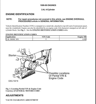
  • 1. 1998-99 ENGINES 2.4L 4-Cylinder ENGINE IDENTIFICATION Vehicle Identification Number (VIN) is stamped on a metal tab, attached to top left end of instrument panel, near the windshield. Engine can also be identified by an engine code (3rd character) stamped on left side of cylinder block. See Fig. 1 . See the ENGINE IDENTIFICATION CODES table. ENGINE IDENTIFICATION CODES Fig. 1: Locating Partial VIN & Engine Code Courtesy of GENERAL MOTORS CORP. ADJUSTMENTS VALVE CLEARANCE ADJUSTMENT NOTE: For repair procedures not covered in this article, see ENGINE OVERHAUL PROCEDURES article in GENERAL INFORMATION. Application VIN Code Engine ID 2.4L DOHC SFI T LD9 1999 Pontiac Grand Am GT 1998-99 ENGINES 2.4L 4-Cylinder 1999 Pontiac Grand Am GT 1998-99 ENGINES 2.4L 4-Cylinder me Wednesday, May 20, 2009 9:20:38 AM Page 1 © 2005 Mitchell Repair Information Company, LLC. me Wednesday, May 20, 2009 9:21:20 AM Page 1 © 2005 Mitchell Repair Information Company, LLC.
  • 2. Engine is equipped with non-adjustable hydraulic valve lifters. TROUBLE SHOOTING REMOVAL & INSTALLATION FUEL PRESSURE RELEASE Disconnect negative battery cable. Loosen fuel filler cap. Install Fuel Pressure Gauge (J-34730-1) on fuel pressure connector of fuel rail. Wrap shop towel around pressure connection when installing fuel pressure gauge to absorb fuel leakage. Install gauge bleed hose into container. Open bleed valve to bleed fuel pressure. COOLING SYSTEM BLEEDING 1. Fill radiator and surge tank to base of filler neck. Install pressure cap on surge tank. Block drive wheels and firmly apply parking brake. Shift automatic transaxle to Park or manual transaxle to Neutral. Start engine. Run until upper radiator hose is hot. Stop engine. 2. Observe coolant level in surge tank or radiator. If not above FULL mark, allow engine to cool and then remove surge tank cap. Add coolant. If low coolant light lights after servicing, remove surge tank cap and add coolant to bring level to COLD FULL mark when system is cold. ENGINE Removal (1998 Models) 1. Release fuel pressure. See FUEL PRESSURE RELEASE . Disconnect negative battery cable. Drain cooling system. Discharge air conditioning system (if equipped) using approved refrigerant NOTE: To trouble shoot mechanical engine components, see ENGINE MECHANICAL in GENERAL TROUBLE SHOOTING article in GENERAL INFORMATION. CAUTION: When battery is disconnected, vehicle computer and memory systems may lose memory data. Driveability problems may exist until computer systems have completed a relearn cycle. For 1998, see appropriate model under COMPUTER RELEARN PROCEDURES in COMPUTER RELEARN PROCEDURES article in GENERAL INFORMATION. For 1999, See appropriate model in COMPUTER RELEARN PROCEDURES article in GENERAL INFORMATION. NOTE: For reassembly reference, label all electrical connectors, vacuum hoses and fuel lines before removal. Also place mating marks on engine hood and other major assemblies before removal. NOTE: On 1998 models, remove engine and transaxle as an assembly through bottom of engine compartment. 1999 Pontiac Grand Am GT 1998-99 ENGINES 2.4L 4-Cylinder me Wednesday, May 20, 2009 9:20:38 AM Page 2 © 2005 Mitchell Repair Information Company, LLC.
  • 3. recovery/recycling equipment. 2. Remove left sound insulator and disconnect push rod from clutch pedal assembly (if equipped). Disconnect control cables, coolant hoses, electrical connectors, vacuum hoses, and fuel lines as necessary. Remove air cleaner assembly. Remove cooling fan. Disconnect air conditioning hose assembly from compressor (if equipped). Discard "O" rings. 3. Remove throttle cable and bracket. Remove power steering pump bolts and pump (leave hoses connected). Disconnect shift cables. Disconnect clutch actuator (slave cylinder) hydraulic line. Remove exhaust manifold and heat shield. See EXHAUST MANIFOLD . 4. Support engine from above with Engine Support Fixture (J-28467-A). Remove coolant recovery tank (leave hoses connected) and position aside. Remove engine mount from timing chain end of engine. Raise and support vehicle. Remove front wheels. Remove right splash shield. Remove engine mount strut and transaxle mount. Separate ball joints from steering knuckles. 5. Put a suitable supporting device under suspension support, crossmember and stabilizer shaft. Remove suspension support and stabilizer shaft. Remove heater outlet hose from radiator outlet pipe. Remove axle shaft from transaxle and intermediate shaft (manual transaxle only) and position aside. 6. Remove flywheel housing cover. Put a suitable supporting device under engine and transaxle assembly and lower vehicle onto support. Mark threads on engine upper support fixture hooks for installation reference. Remove engine upper support fixture hooks. Raise vehicle slowly from engine and transaxle assembly. Separate engine from transaxle (note bolt location for reassembly reference). Installation 1. Assemble engine to transaxle, ensuring bolts are in correct locations. On automatic transaxle models, clean torque converter bolts and bolt holes. Apply sealant to bolts. On all models, position engine and transaxle assembly under engine compartment. Lower vehicle until transaxle mount is aligned. Install transaxle mount bolt. 2. Install Engine Support Fixture (J-28467-A) above engine, adjusting it to previous setting. Install engine mount at timing chain end of engine. Install engine mount at transaxle. Raise vehicle. Remove supporting device from below engine and transaxle assembly. Install axle shafts. 3. Install suspension support, crossmember and stabilizer shaft assembly. Tighten suspension support rear bolts, center bolts and then front bolts to specification. See TORQUE SPECIFICATIONS table. Connect ball joints. Install engine mount strut. To complete installation, reverse removal procedure. Evacuate and charge air conditioning system. Fill cooling system and crankcase. Removal (1999 Models) 1. Release fuel pressure. See FUEL PRESSURE RELEASE . Disconnect negative battery cable. Drain cooling system and engine oil. Remove fuel rail assembly, air intake duct from air cleaner, ignition coil and module assembly. Disconnect control cables, coolant hoses, electrical connectors, vacuum hoses, and fuel lines as necessary. 2. Unbolt power steering pump and secure aside. Remove air intake duct bracket. Remove cruise control assembly and set aside. Install J 28467-360 engine support fixture. Remove fan belt and engine mount assembly. Raise engine using support fixture, then remove engine mount bracket. NOTE: On 1999 models, remove engine while leaving transmission in vehicle. 1999 Pontiac Grand Am GT 1998-99 ENGINES 2.4L 4-Cylinder me Wednesday, May 20, 2009 9:20:38 AM Page 3 © 2005 Mitchell Repair Information Company, LLC.
  • 4. 3. Raise and support vehicle. Remove front wheels and right splash shield. Remove crankshaft balancer. Remove torque converter bolts and oxygen sensor. Lower vehicle. Remove generator and starter. Remove exhaust brace bolt and exhaust manifold heat shield. Disconnect exhaust pipe from exhaust manifold. 4. Unbolt A/C compressor and secure aside. Remove oil pan-to-bellhousing bolts. Remove transmission mount. Remove transmission-to-engine bolts. Install engine hoist, then remove engine while supporting transaxle. Installation To install, reverse removal procedure. Tighten all fasteners to specifications. See TORQUE SPECIFICATIONS table. Fill engine fluids, and bleed cooling system. See COOLING SYSTEM BLEEDING . INTAKE MANIFOLD Removal 1. Disconnect negative battery cable. Disconnect electrical connectors and vacuum hoses from intake manifold components as necessary. Disconnect air intake tube. Remove throttle cable bracket. 2. Remove generator mount bolt. Remove EGR pipe from EGR adapter. Remove intake manifold nuts and bolts. Remove intake manifold and gasket. Installation Tighten all intake manifold nuts and bolts to specification in sequence. See Fig. 2 . See TORQUE SPECIFICATIONS table. To complete installation, reverse removal procedure. WARNING: Never remove intake manifold while engine is hot. Intake manifold is made of composite plastic and can be damaged if removed while engine is hot. NOTE: Intake manifold gasket is reusable unless damaged. Numbered side of intake manifold gasket must face intake manifold. 1999 Pontiac Grand Am GT 1998-99 ENGINES 2.4L 4-Cylinder me Wednesday, May 20, 2009 9:20:38 AM Page 4 © 2005 Mitchell Repair Information Company, LLC.
  • 5. Fig. 2: Intake Manifold Tightening Sequence Courtesy of GENERAL MOTORS CORP. EXHAUST MANIFOLD Removal 1. Disconnect negative battery cable. Disconnect oxygen sensor connector. Raise and support vehicle. Remove exhaust manifold brace bolt. Remove upper heat shield. Disconnect exhaust pipe flex decoupler from manifold. DO NOT allow flex decoupler to bend more than 3 degrees in any direction, as damage will result. 2. Pull down and back on exhaust pipe to disengage it from manifold. Lower vehicle. Remove exhaust manifold nuts. Remove exhaust manifold, seals and gaskets. Installation To install, reverse removal procedure using NEW gaskets. Tighten bolts to specification in sequence. See TORQUE SPECIFICATIONS table. See Fig. 3 . If oxygen sensor was removed, coat threads with Anti-Seize Compound (5612695) before installation. 1999 Pontiac Grand Am GT 1998-99 ENGINES 2.4L 4-Cylinder me Wednesday, May 20, 2009 9:20:39 AM Page 5 © 2005 Mitchell Repair Information Company, LLC.
  • 6. Fig. 3: Exhaust Manifold Tightening Sequence Courtesy of GENERAL MOTORS CORP. CYLINDER HEAD Removal 1. Disconnect negative battery cable. Drain cooling system. Remove throttle body-to-air cleaner duct. Disconnect heater hose and throttle body hose from water outlet. Remove power brake vacuum hose from throttle body. 2. Disconnect electrical connectors, vacuum hoses, and coolant hoses as necessary. Remove generator mount bolt. Remove intake manifold. See INTAKE MANIFOLD . Remove generator mount bolt. 3. Reinstall generator mount bolt. Install Engine Support Fixtures (J-28467-400 and J-28467-A). Remove exhaust manifold. See EXHAUST MANIFOLD . Remove ignition coil and module assembly connectors. Remove attaching bolts and remove coil assembly from camshaft housing by pulling it straight up. See Fig. 12 . 4. Disconnect camshaft position sensor connector. Remove power steering pump. Remove fuel line retaining clamp from bracket on top of intake camshaft housing. Remove fuel rail from cylinder head, and leaving fuel lines attached, position on top of master cylinder. Cover injector openings in head and injector nozzles. 5. Remove timing chain and sprocket. See TIMING CHAIN, SPROCKETS & TENSIONER . CAUTION: Turn camshaft housing upside down immediately after removing from vehicle, or valve lifters will fall out and may be damaged. 1999 Pontiac Grand Am GT 1998-99 ENGINES 2.4L 4-Cylinder me Wednesday, May 20, 2009 9:20:39 AM Page 6 © 2005 Mitchell Repair Information Company, LLC.
  • 7. Disconnect timing chain housing at intake camshaft housing but DO NOT remove from vehicle. Remove bolts attaching intake camshaft housing to cylinder head bolts in reverse of tightening sequence. See Fig. 13 . Remove camshaft housing. Repeat procedure with exhaust camshaft housing. 6. Disconnect radiator inlet hose from coolant outlet and disconnect coolant temperature sensor connectors. Remove cylinder head bolts in reverse order of tightening sequence. See Fig. 4 . Remove cylinder head and gasket. See CYLINDER HEAD under OVERHAUL. Installation Clean threads of cylinder head bolts and bolt holes. Lightly coat bolt threads with engine oil. Install NEW gasket, ensuring all holes are aligned with cylinder block. Install cylinder head and tighten cylinder head bolts to specification in sequence. See TORQUE SPECIFICATIONS table. To complete installation, reverse removal procedure. See Fig. 4 . Fig. 4: Cylinder Head Bolt Tightening Sequence Courtesy of GENERAL MOTORS CORP. FRONT COVER CAUTION: DO NOT use a thread tap to clean cylinder head bolt holes. Remove all fluids from bolt holes. 1999 Pontiac Grand Am GT 1998-99 ENGINES 2.4L 4-Cylinder me Wednesday, May 20, 2009 9:20:39 AM Page 7 © 2005 Mitchell Repair Information Company, LLC.
  • 8. Removal 1. Disconnect negative battery cable. Drain cooling system. Remove coolant recovery tank. Remove serpentine drive belt. Remove generator (leave wiring attached). Attach Engine Support Fixture (J-28467- 400 and J-28467-A) to engine and generator stud. Remove bolts from upper half of front cover. 2. Remove engine mount assembly from timing chain end of engine. Remove engine mounting bracket adapter. Raise and support vehicle. Remove right front wheel and splash shield. Remove crankshaft balancer bolt. Remove crankshaft balancer with a puller. Remove lower bolts from front cover. Lower vehicle. Remove front cover and gaskets. Installation To install, reverse removal procedure. Cover gasket is reusable if not damaged. Lubricate front seal with grease before installing crankshaft balancer. To complete installation, reverse removal procedure. Tighten nuts and bolts to specification. See TORQUE SPECIFICATIONS table. Fill cooling system. CRANKSHAFT FRONT SEAL Removal & Installation Disconnect negative battery cable. Remove front cover. See FRONT COVER . Support cover, and drive seal through rear of cover. Take care not to damage cover. Note direction of seal installation. To install seal, use Seal Installer (J-36010). TIMING CHAIN, SPROCKETS & TENSIONER Removal 1. Disconnect negative battery cable. Remove front cover. See FRONT COVER . See Fig. 5 . Rotate crankshaft in normal direction of rotation (clockwise, as viewed from front of engine) until cylinder No. 1 is at TDC of compression stroke. 2. The camshaft sprocket dowel pin hole should line up with holes on timing chain housing. The crankshaft sprocket keyway should point upwards. See Fig. 5 . Remove timing chain guides. Raise and support vehicle. Ensure slack in chain is above tensioner assembly, then remove chain tensioner. 3. Note that timing chain must be disengaged from any wear grooves in tensioner shoe before removing shoe. Slide a screwdriver blade between chain and tensioner shoe, while pulling shoe outward (this should disengage chain from wear grooves in shoe). If timing chain is not difficult to remove, go to step 5 . If it is difficult to remove timing chain shoe, go to next step. NOTE: This procedure has been revised due to GM service manual update (SMU) # 00- 06-01-002 dated Feb, 2000 CAUTION: To prevent severe engine damage, carefully follow procedure. 1999 Pontiac Grand Am GT 1998-99 ENGINES 2.4L 4-Cylinder me Wednesday, May 20, 2009 9:20:39 AM Page 8 © 2005 Mitchell Repair Information Company, LLC.
  • 9. Thank you very much for your reading. Please Click Here. Then Get COMPLETE MANUAL. NO WAITING NOTE: If there is no response to click on the link above, please download the PDF document first and then click on it.
  • 10. 4. Lower vehicle. Hold intake camshaft sprocket with Sprocket Wrench (J-39579) and remove sprocket bolt. Remove washer from bolt and rethread bolt into camshaft by hand. Remove camshaft sprocket using a 3- jaw puller. DO NOT attempt to pry sprocket off or damage will result. 5. Remove tensioner assembly bolts and tensioner. Mark outer surface of timing chain and crankshaft sprocket for reassembly reference. Remove timing chain. Fig. 5: Assembled View Of Timing Chain, Sprockets & Tensioner Courtesy of GENERAL MOTORS CORP. Installation CAUTION: To prevent damage to sprocket or timing chain housing, use a puller to remove sprocket from camshaft. DO NOT pry sprocket from camshaft. 1999 Pontiac Grand Am GT 1998-99 ENGINES 2.4L 4-Cylinder me Wednesday, May 20, 2009 9:20:39 AM Page 9 © 2005 Mitchell Repair Information Company, LLC.
  • 11. 1. Install the camshaft sprockets. The sprockets are identical and interchangeable. Clean the old sealer off of the bolts with a wire brush. Clean the threaded hole in the camshaft with a nylon bristle brush. Coat the camshaft bolts with Adhesive/Sealant Compound (GM 1234593) or equivalent. See Fig. 6 . 2. Install the camshaft sprocket bolts and washers while holding the sprockets with Tool (J- 39579). Tighten the bolts to 52 ft. lbs. (70 N.m). 3. Install Tool (J-36008-A) through the holes in the camshaft sprockets and into the holes in the timing chain housing. This will position the camshaft for correct timing. Use the following steps if the camshafts are out of position and must be rotated more than 1/8 turn in order to install the alignment dowel pins: A. The crankshaft must be rotated 90 degrees clockwise from TDC to give the valves adequate clearance to open. B. Once the camshafts are in position and the dowels are installed, rotate the crankshaft counter clockwise back to TDC. 4. Install the timing chain over the exhaust camshaft sprocket around the coolant pump sprocket and around the crankshaft sprocket. Remove the alignment dowel pin from the intake camshaft. Use Tool (J-39579) in order to rotate the intake camshaft sprocket counter clockwise enough to allow the timing chain to slide over the intake camshaft sprocket. Release Tool (J-39579). The length of the chain between the two camshaft sprockets will tighten. 5. If properly timed, the intake camshaft alignment dowel pin will slide in easily. If the dowel pin does not fully index, the camshafts are not timed correctly and the procedure must be repeated. Leave the alignment dowel pins installed. The keyway on the crankshaft and the mark on the cylinder block should be aligned when the slack is removed from the chain between the intake camshaft sprocket and the crankshaft sprocket. If the mark and the keyway are not aligned, move the chain one tooth forward or rearward. Remove the slack and recheck the marks. NOTE: Ensure camshaft sprocket alignment pins are in the cylinder block and the timing chain housing, prior to installing the timing chain housing. The camshaft sprocket alignment pins ensure proper chain housing and front cover location for correct front oil seal to crankshaft alignment. CAUTION: DO NOT rotate the crankshaft clockwise to TDC. Valve or piston damage could occur. The timing chain and crankshaft sprocket must be put in a specific direction for chain noise and wear considerations. The surfaces that were marked during removal should be showing when the chain and crankshaft sprocket are installed. NOTE: Use the following steps in order to reset the timing chain tensioner assembly to the zero position: A. Reset the timing chain tensioner assembly. B. Insert the tensioner plunger assembly into the tensioner housing. C. With the tensioner plunger fully extended, turn the complete 1999 Pontiac Grand Am GT 1998-99 ENGINES 2.4L 4-Cylinder me Wednesday, May 20, 2009 9:20:39 AM Page 10 © 2005 Mitchell Repair Information Company, LLC.
  • 12. 6. Check the plunger to ensure the plunger is out of the cylinder at the correct dimension. The correct dimension for the plunger to extend out of the cylinder is .070" (1.7 mm) maximum. See Fig. 8 . Loosely install the tensioner assembly and bolts to the timing chain housing. See Fig. 9 . Install the timing chain tensioner shoe on the stud. Apply hand pressure to the timing chain tensioner shoe until the locking tab seats in the groove in the stud. Tighten the timing chain tensioner bolts. DO NOT over tighten. Tighten the bolts to 89 INCH lbs. (10 N.m). 7. Release the timing chain tensioner plunger using the following procedure: A. Using a flat blade screwdriver, cotter pin remover, or a similar tool, press firmly against the face of the timing chain tensioner plunger. See Fig. 10 . B. Depress the timing chain tensioner plunger until the plunger is bottomed out in the bore of the timing chain tensioner. See Fig. 8 . C. Release the tensioner plunger. See Fig. 10 . The plunger should press firmly against the back of the timing chain tensioner shoe. Remove Tool (J- 36008-A) from the camshaft sprockets. 8. Rotate the crankshaft clockwise two full rotations. Align the crankshaft keyway with the mark on the cylinder block and reinstall the alignment dowel pins. The alignment dowel pins will slide in easily if the engine is timed correctly. Install the timing chain guides. assembly upside down on a bench or other flat surface. See Fig. 7 . D. With the plunger face against the workbench, press firmly on the bottom of the tensioner housing. E. Compress the plunger until the plunger is seated flush in the tensioner. See Fig. 8 . CAUTION: If the timing chain tensioner plunger is not released from the installation position, engine damage will occur when the engine is started. NOTE: If the timing chain tensioner plunger cannot be depressed, the plunger is not properly reset and the procedure for resetting the timing chain tensioner should be repeated. CAUTION: Beginning with the 1998 model year, the timing chain on the LD9 (VIN T) Twin Cam Engine is different from the chain found on earlier versions of this engine, and is not to be replaced with a timing chain from earlier model year engines. The timing sprockets were also changed beginning in 1998, and the shape of the chain links matches the sprockets. Engine damage may result if the wrong timing chain is used. The timing chain and the crankshaft sprocket must be marked so that they are reinstalled in the same side facing out at the time of assembly. 1999 Pontiac Grand Am GT 1998-99 ENGINES 2.4L 4-Cylinder me Wednesday, May 20, 2009 9:20:39 AM Page 11 © 2005 Mitchell Repair Information Company, LLC.
  • 13. Fig. 6: Installing Timing Chain Sprockets Courtesy of GENERAL MOTORS CORP. 1999 Pontiac Grand Am GT 1998-99 ENGINES 2.4L 4-Cylinder me Wednesday, May 20, 2009 9:20:39 AM Page 12 © 2005 Mitchell Repair Information Company, LLC.
  • 14. Fig. 7: Released View Of Timing Chain Tensioner Assembly Courtesy of GENERAL MOTORS CORP. 1999 Pontiac Grand Am GT 1998-99 ENGINES 2.4L 4-Cylinder me Wednesday, May 20, 2009 9:20:39 AM Page 13 © 2005 Mitchell Repair Information Company, LLC.