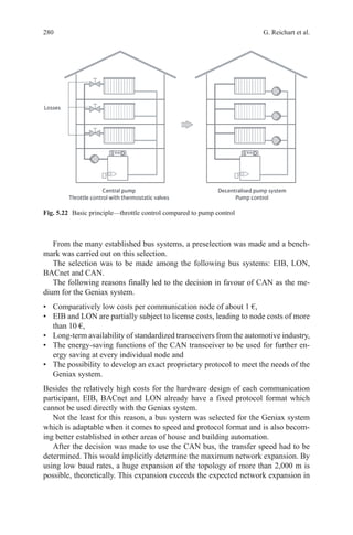
This document provides an overview and preface for the book "CAN System Engineering: From Theory to Practical Applications". It discusses the origins and growth of Controller Area Network (CAN) technology. CAN was originally developed by Bosch in the 1980s for use in automotive applications. It has since been widely adopted for applications in many industries. The book contains technical details on CAN contributed by various specialists. It covers topics such as physical layer, data link layer, higher level protocols, applications, and testing of CAN systems.


![xxv
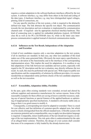
UART Universal Asynchronous Receiver Transmitter—Universal asyn-
chronous receiver [and] transmitter electronic circuit for the rea-
lization of digital, serial interfaces and byte-oriented protocols
UDC User-defined Channel—Acronym for logical communication
channel ARINC 825 for custom data
UDH/UDL High/Low Priority User-Defined Data
UDP/IP User Datagram Protocol—Protocol for data transfer on the
Internet
UDS Unified Diagnostic Services
UML Universal Modelling Language
USB Universal Serial Bus
USIC Universal Serial Interface Controller
UT Upper Tester—Part of the test system, which serves the IUT
interface to higher layers
UTP Unshielded Twisted Pair—Unshielded, twisted-pair cable, often
used for CAN
V
VDA Association of the Automotive Industry
VHDL-AMS Very High Speed Integrated Circuit Hardware Description
Language
VFB Virtual Function Bus
VIN Vehicle Identification Number
VLAN Virtual Local Area Network—Virtual local area network, The
method for displaying a plurality of logical networks on a single
physical network, such as Ethernet
VRC Vertical Redundancy Check
W
WK Wake—Local Wake-pin with which the transceiver can be awa-
kened, for example by means of switches from sleep mode
WUF Wake-up Frame—CAN message with specific useful data that
exist only to wake from partial network transceivers on the
busWWH-OBD Wold-wide harmonized OBD—globally harmo-
nized OBD
X
XLP eXtreme Low Power
XML Extensible Markup Language—free “extensible markup lan-
guage” for representing hierarchically structured data in the
form of text data
XOR eXclusive OR
Abbreviations](https://image.slidesharecdn.com/1447156129can-150305165128-conversion-gate01/85/1447156129-can-24-320.jpg)
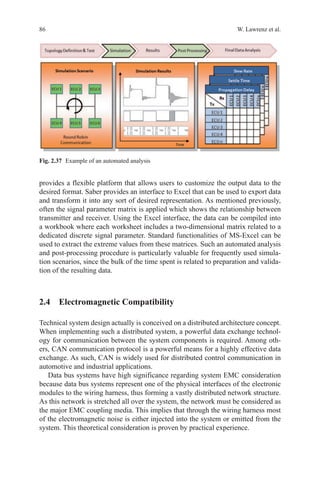
![18 W. Lawrenz
1.2.6 Bit-Timing and Synchronization
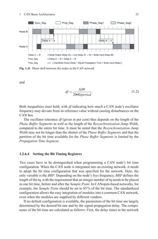
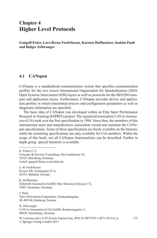
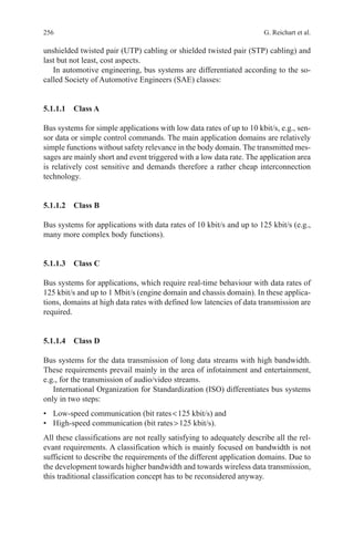
CAN supports data rates of less than 1 kbit/s and also up to 1,000 kbit/s. Each
CAN node in a CAN network is clocked by an individual clock generator (usually
a quartz oscillator). The parameters of the bit time (i.e. the inverse of the bit rate)
are individually adjusted in each CAN node, to achieve a uniform bit rate even from
different oscillator frequencies (fosc).
The parameters are written into the configuration registers of the bit timing logic
( BTL). The Baud Rate Prescaler ( BRP) determines the length of the time quantum
(tq), which is the basic unit of the bit time, while the timing segments determine the
number of time quanta in the bit time. The clock frequencies of these oscillators are
not absolutely stable, caused by temperature or voltage fluctuations and the aging of
components. As long as the deviations remain within a certain oscillator tolerance
range ( df), the CAN nodes are able to compensate for the differences by synchroniz-
ing to the edges in CAN frames.
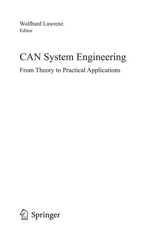
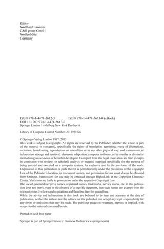
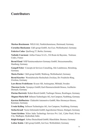
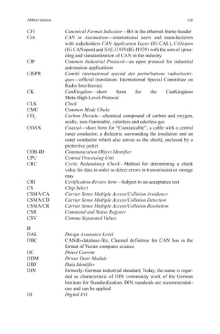
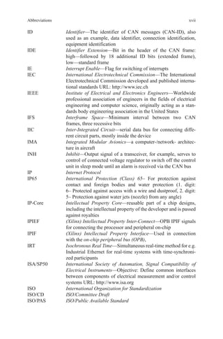
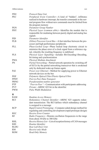
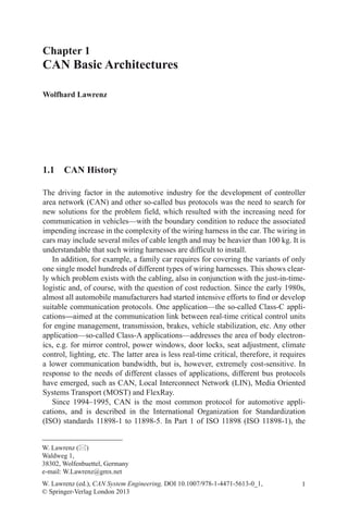
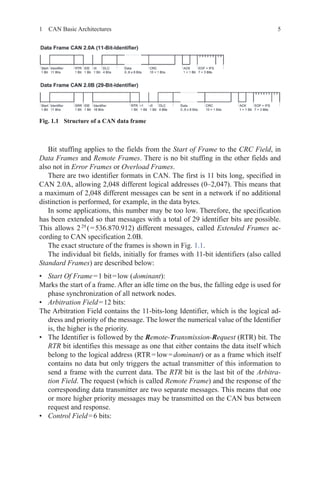
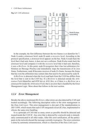
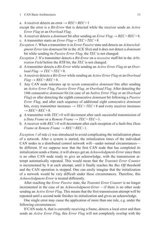
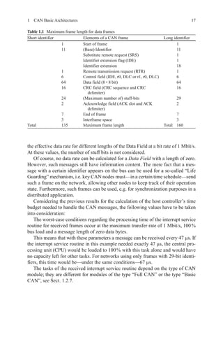
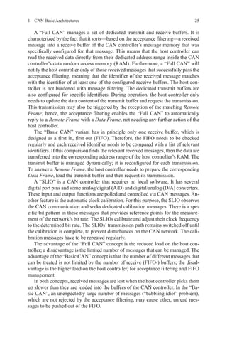
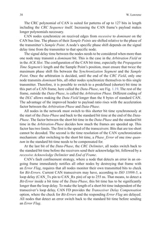
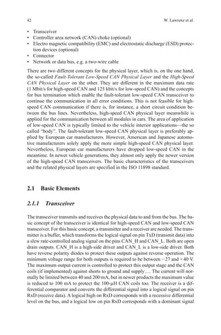
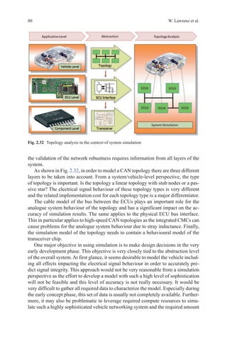
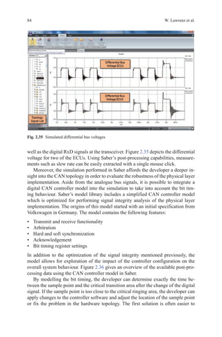
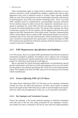
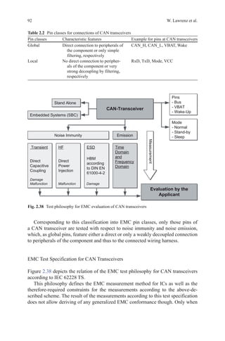
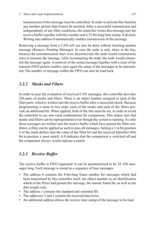
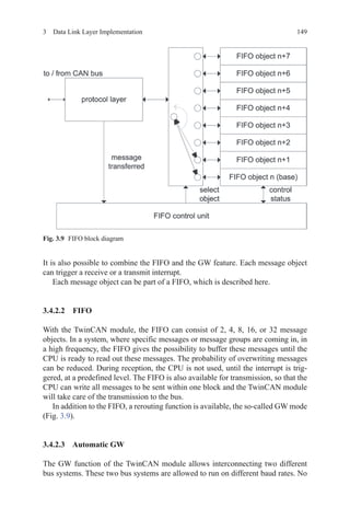
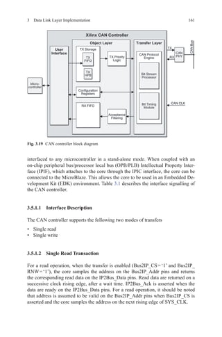
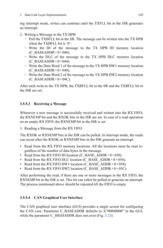
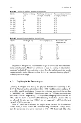
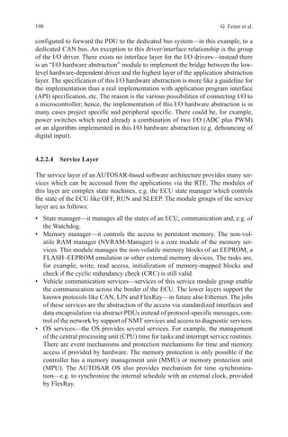
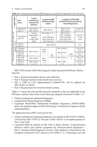
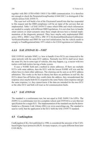
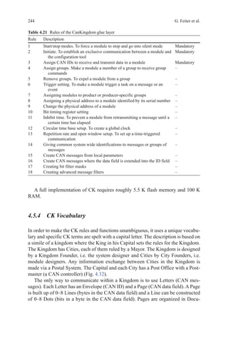
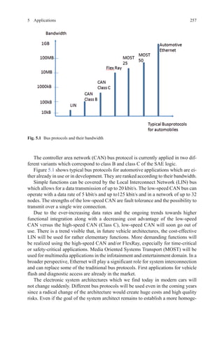
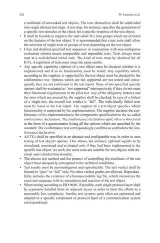
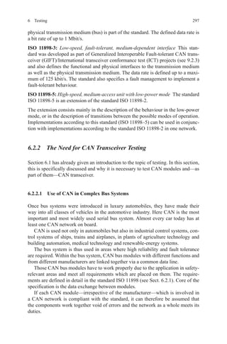
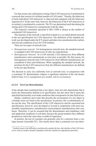
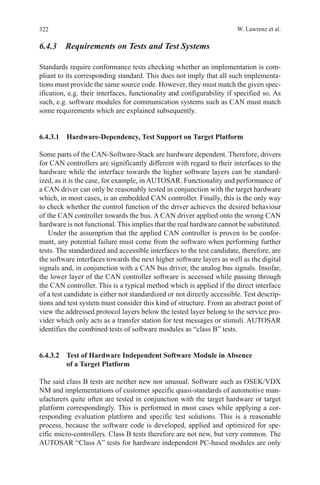
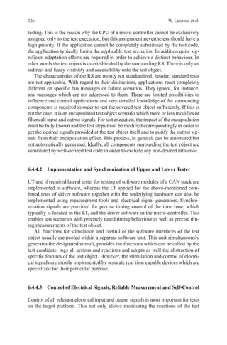
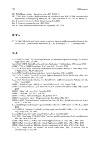
According to the CAN specification, a CAN bit time is divided into four seg-
ments (see Fig. 1.8): the Synchronization Segment, the Propagation Time Segment,
the Phase Buffer Segment 1 and the Phase Buffer Segment 2. Each segment consists
of a certain (programmable) number of time quanta. The duration of a time quantum
(tq
) is determined by the CAN controller’s system clock fsys
and the BRP: tq
= BRP/
fsys
. Common clocks are fsys
= fosc
or fsys
= fosc
/2.
The synchronization segment, Sync_Seg, is that part of the bit time where edg-
es of the CAN bus level are expected to occur. The Propagation Time Segment,
Prop_Seg, is intended to compensate for the physical delay times within the CAN
network. The Phase Buffer Segments, Phase_Seg1 and Phase_Seg2, surround the
Sample Point. The (re-) synchronization jump width ( SJW) defines how far a re-
synchronization may move the Sample Point inside the limits, defined by the Phase
Buffer Segments.
The individual parameters are configurable in the following ranges:
• Sync_Seg: 1
• Prop_Seg: [1…8]
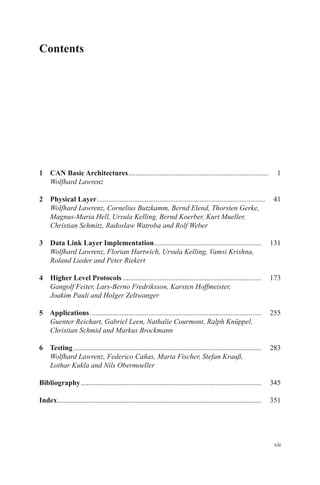
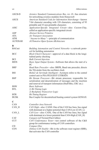
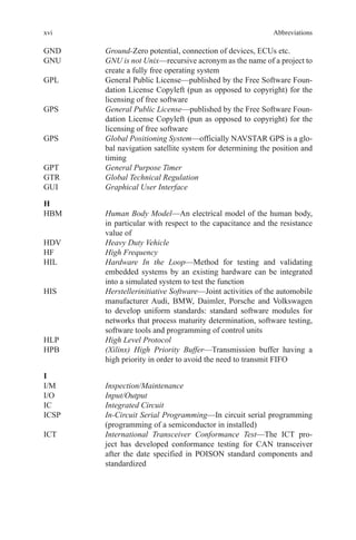
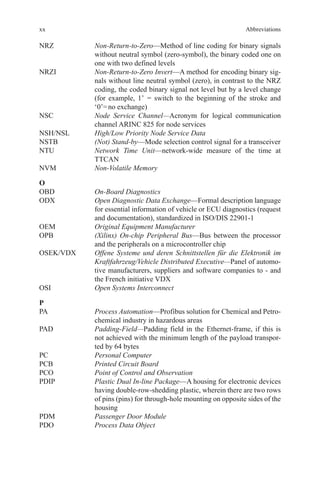
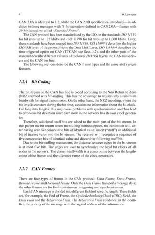
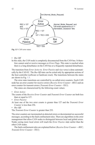
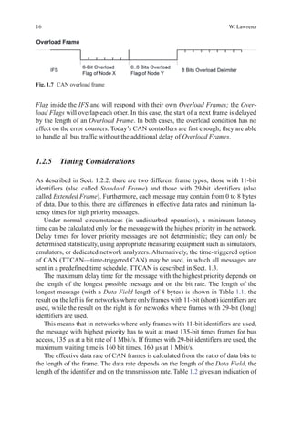
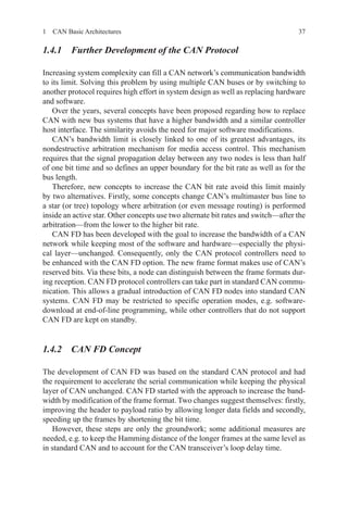
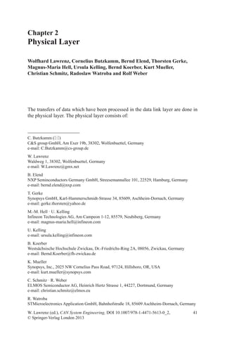
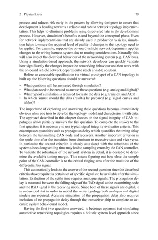
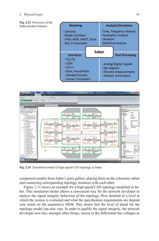
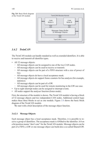
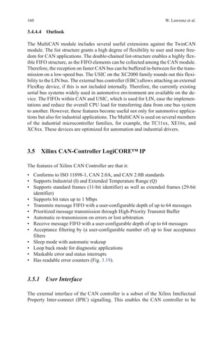
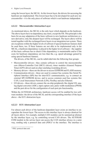
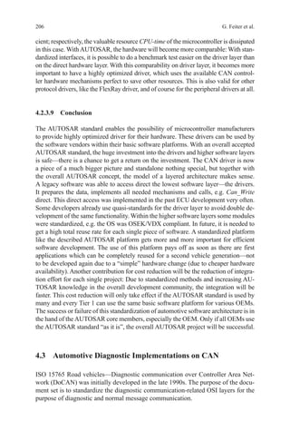
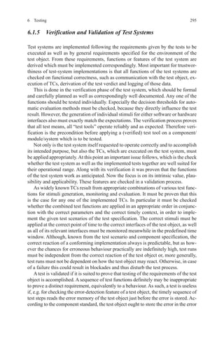
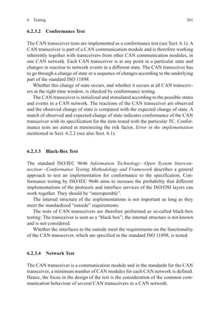
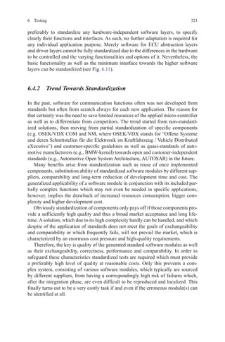
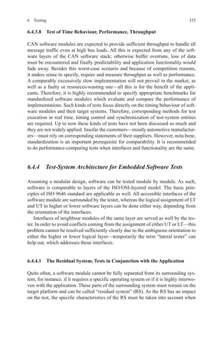
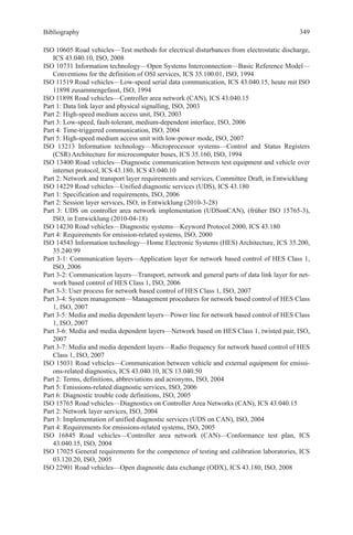
Data field
in bytes
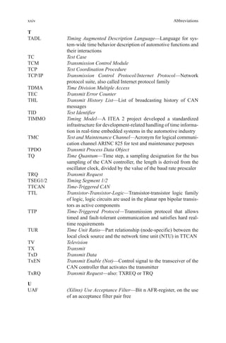
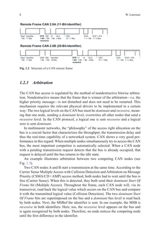
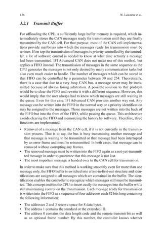
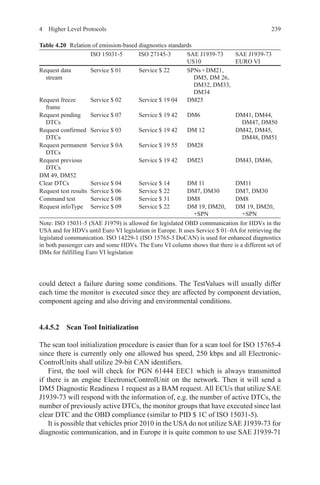
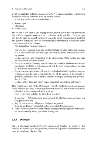
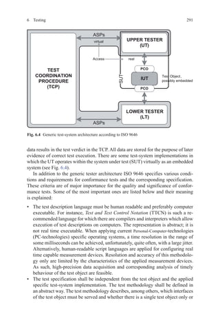
Effective data rate for frames with
11-bit identifier 29-bit identifier
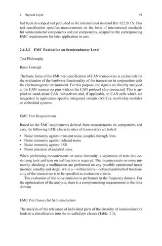
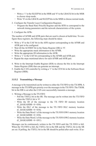
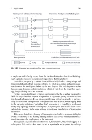
0 ― ―
1 72.1 kbit/s 61.1 kbit/s
2 144.1 kbit/s 122.1 kbit/s
3 216.2 kbit/s 183.2 kbit/s
4 288.3 kbit/s 244.3 kbit/s
5 360.4 kbit/s 305.3 kbit/s
6 432.4 kbit/s 366.4 kbit/s
7 504.5 kbit/s 427.5 kbit/s
8 576.6 kbit/s 488.5 kbit/s
Table 1.2 Effective data rate
at 1 Mbit/s](https://image.slidesharecdn.com/1447156129can-150305165128-conversion-gate01/85/1447156129-can-42-320.jpg)
![191 CAN Basic Architectures
• Phase_Seg1: [1…8]
• Phase_Seg2: [1…8]
• SJW: [1…4]
• BRP: [1…32]
In most CAN implementations, the sum of ( Prop_Seg + Phase_Seg1) is collected
(as TSEG1) together with Phase_Seg2 (as TSEG2) in a first configuration register,
while SJW and BRP are collected in a second register. It should be noted that the
values programmed into these bit timing registers are—for each of TSEG1, TSEG2,
SJW and BRP—the formal values reduced by one; hence, the values are written
[0…n – 1] instead of [1…n]. This allows, for example, to represent SJW (actual
range [1…4]) by only two bits. When Prop_Seg and Phase_Seg1 are configured as
a sum, Prop_Seg may be even larger than 8 while Phase_Seg1 will be correspond-
ingly shorter.
Therefore, the length of a bit time is (programmed values) [TSEG1 + TSEG2 + 3]
tq or (formal values) [Sync_Seg + Prop_Seg + Phase_Seg1 + Phase_Seg2] tq.
The sequential flow of the bit time and possible synchronizations are controlled
by the CAN protocol controller’s BTL, a state machine that is evaluated once per
time quantum. The BTL has the task to evaluate the CAN bus level and to determine
the position of the Sample Point. The remaining part of the CAN protocol control-
ler, the Bit Stream Processor (BSP) state machine, is evaluated only once per bit
time, at the Sample Point, with the CAN bus level evaluated at the Sample Point
taken as the sampled bit value.
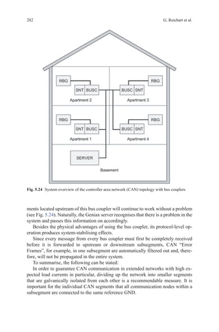
1.2.6.1 “Hard” and “Soft” Synchronization
At each time quantum, the CAN controller’s BTL compares the actual level of
the CAN bus with the stored value of the last Sample Point, to detect edges for
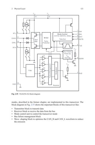
synchronization.
There are two types of synchronization:
• “Hard” synchronization
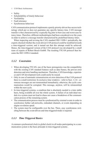
Fig. 1.8 Bit timing](https://image.slidesharecdn.com/1447156129can-150305165128-conversion-gate01/85/1447156129-can-43-320.jpg)
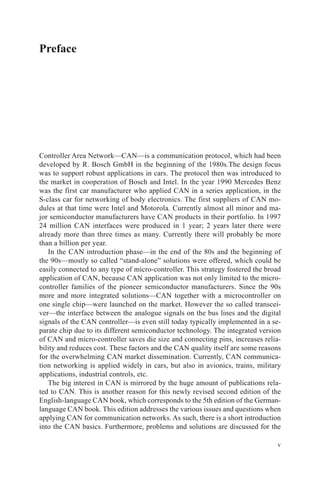
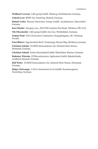
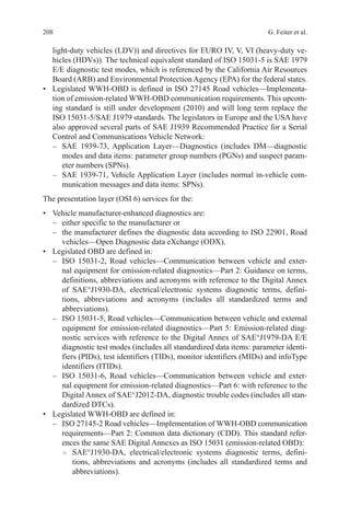
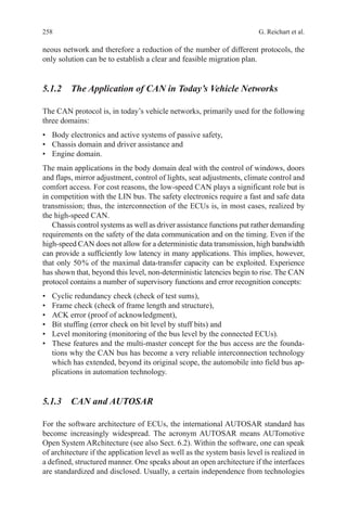
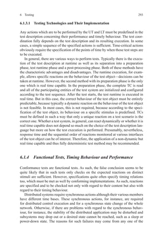
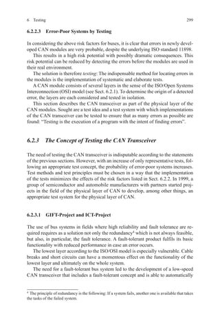
![22 W. Lawrenz
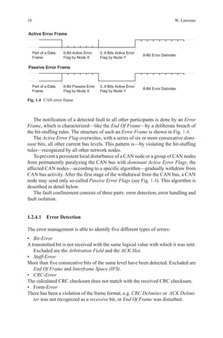
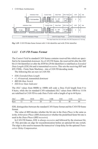
Delay A → B) after its Sync_Seg. Its Phase_Seg1 may not yet have started at that
time, since the beginning of Phase_Seg1 is the earliest position of A’s Sample Point
if that Sample Point is virtually shifted by clock tolerance. Prop_Seg must therefore
be programmed to a value of 2 • Delay A → B (rounded up to the nearest integer
multiple of tq), as shown in Fig. 1.11.
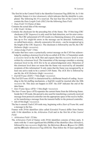
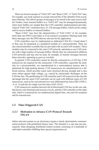
The Propagation Time Segment must be programmed to a length that ensures
edges to be seen before the onset of Phase_Seg1, even when the edges are affected
by the maximum signal propagation delay. The Phase Buffer Segments before and
after Sample Point have to be left for compensating oscillator tolerances. The im-
pact of the bit time parameters on the oscillator tolerance df is shown by the formu-
lae [1.1] and [1.2].
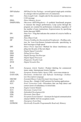
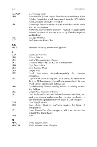
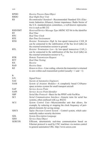
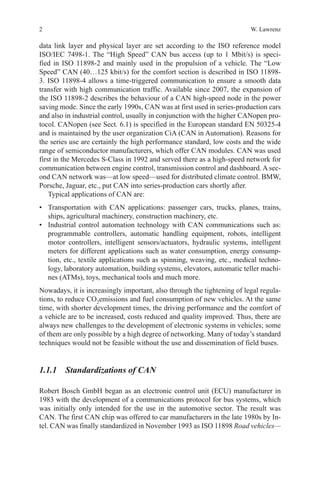
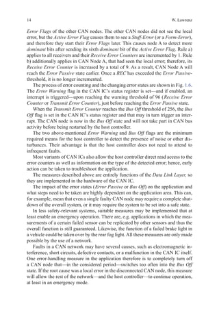
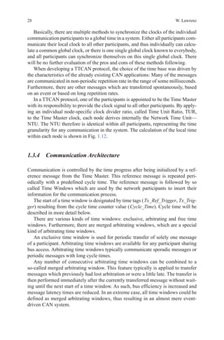
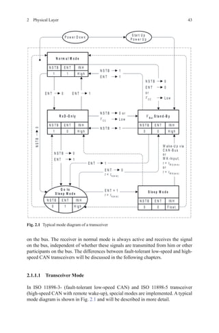
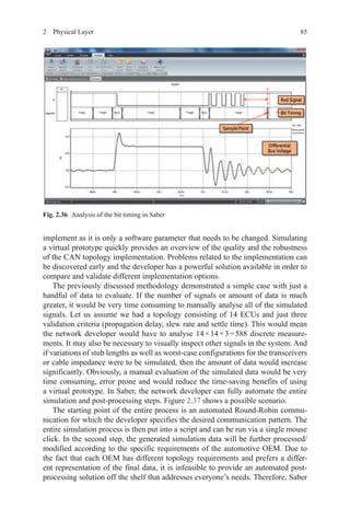
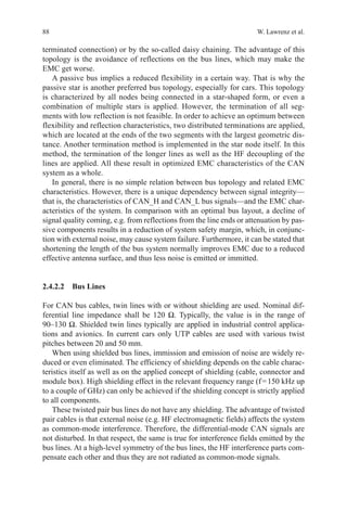
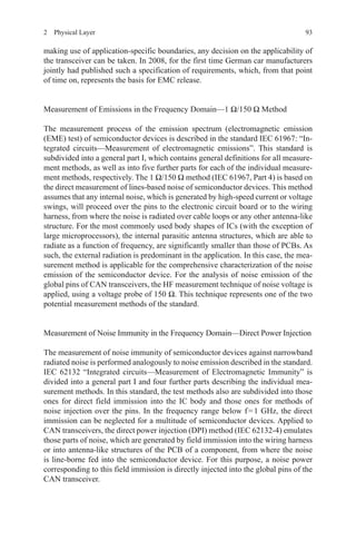
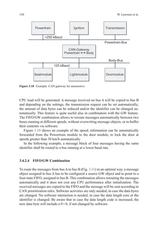
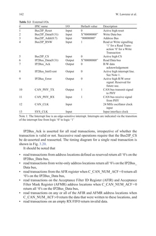
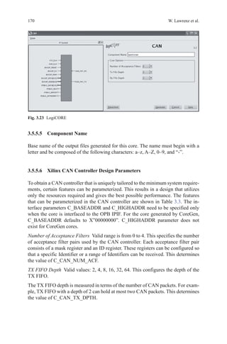
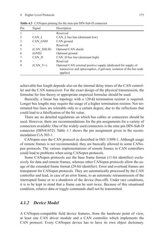
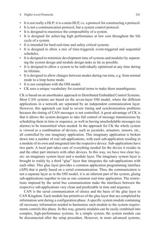
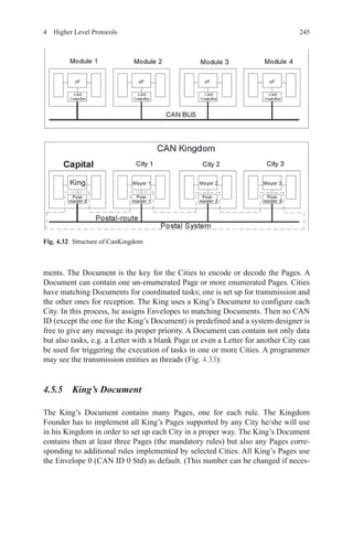
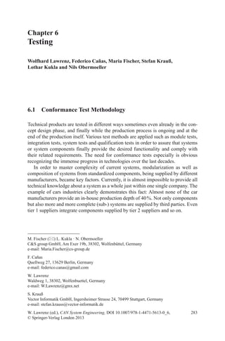
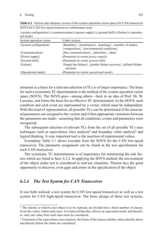
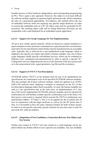
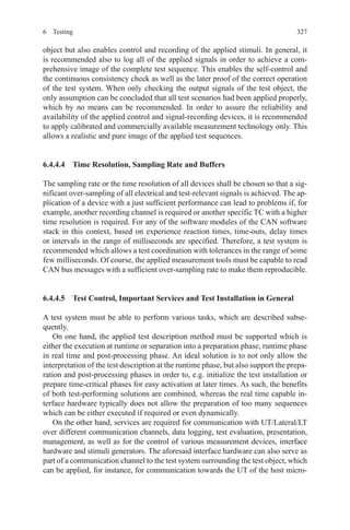
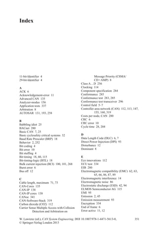
Some CAN implementations provide an optional so-called Three_Sample_Mode.
In this mode, a digital low-pass filter is set before the CAN bus input of the BTL.
Three Sample Points are not present in one bit time, but the bit value at the Sample
Point is generated from the last three values of the CAN bus input (strobed each tq),
evaluated by majority voting. The majority voting filters out spikes, but the CAN
bus input signal is delayed by at least one tq and the Propagation Time Segment
must be extended accordingly.
1.2.6.3 Oscillator Tolerance
The formulae [1.1] and [1.2] are used to calculate the oscillator tolerance:
df
Phase Seg Phase Seg
Bitperiod Phase Seg
=
−
min( _ , _ )
•( • _ )
1 2
2 13 2
(1.1)
Fig. 1.10 Filtering of short dominant spikes](https://image.slidesharecdn.com/1447156129can-150305165128-conversion-gate01/85/1447156129-can-46-320.jpg)
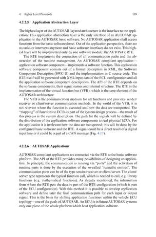
![24 W. Lawrenz
need to be determined. These consist of the delay on the CAN bus line (typically
5 ns/m), the transit times through the node’s transceivers and, for example, in in-
dustrial applications, through additional optocouplers for galvanic isolation. The
determined signal propagation delay gives an upper limit for the possible bit rate,
since the CAN bit time (reciprocal of the bit rate) must be significantly longer than
twice this value.
Then, based the desired bit rate and the available system clock frequency fsys,
BRP values are selected, that can produce the desired bit time from an integer num-
ber (in the range of [5…25]) of tq, with tq = BRP/fsys. The length of Prop_Seg
needs to be twice the signal propagation delay, rounded up to the next integer mul-
tiple of tq. Hence, the BRP value must allow Prop_Seg to be in the range of [1…8]
(if needbe, in the range of [1…15] when Prop_Seg and Phase_Seg1 are combined
in TSEG1).
The desired bit time must be at least 3 tq longer than the time required for Prop_
Seg. Sync_Seg is always 1 tq long; the rest is left for the two Phase Buffer Segments.
Phase_Seg1 and Phase_Seg2 should have the same length, but if the subtraction
(bit time – [Sync_Seg + Prop_Seg]) results in an odd number of tq, Phase_Seg2 is
set longer: Phase_Seg2 = Phase_Seg1 + 1. In order to optimize the oscillator toler-
ance, SJW needs to be set to the highest possible value, but not longer than one
Phase Buffer Segment. The oscillator tolerance is mainly determined by the relation
between the length of the Phase Buffer Segments and the length of the bit time.
The combination of Prop_Seg = 1 and Phase_Seg1 = Phase_Seg2 = SJW = 4
yields has an oscillator tolerance of 1.58 %, the largest value possible in the CAN
protocol. This combination, with a Propagation Time Segment of only 10 % of the
bit time, is not suitable for short bit times; at a 40-m bus length, it can be used for
bit rates up to 125 kbit/s (with a bit time of at least 8 µs).
The bit timing concept of the CAN protocol has sufficient reserves, so that small
deviations from the nominal values (temperature changes or aging of the compo-
nents may cause, e.g. drift of the oscillators or longer signal delays) do not directly
cause disturbances in the communication; but the deviations may make the network
less resilient with regard to external sources of error (e.g. EMI). If a bit is disturbed
at its Sample Point, the faulty bit is intercepted by higher protocol layers (CRC
code, bit-stuffing, etc.) and the message is invalidated.
1.2.7 Characteristics of CAN Controllers
In principle, there are three types of CAN controllers: “Full CAN”, “Basic CAN”
and serial linked input/output (SLIO). CAN controllers are internally partitioned in
CAN protocol controller and CAN message handler. While the function of the CAN
protocol controller is defined by the CAN specification, the function of the CAN
message handler is application specific. Different concepts have been developed for
the CAN message handling.](https://image.slidesharecdn.com/1447156129can-150305165128-conversion-gate01/85/1447156129-can-48-320.jpg)

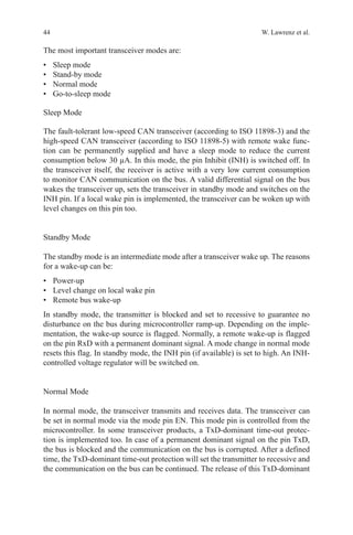
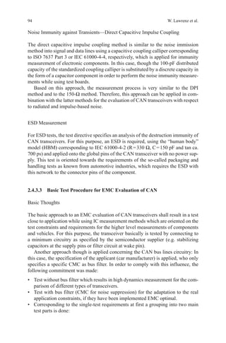
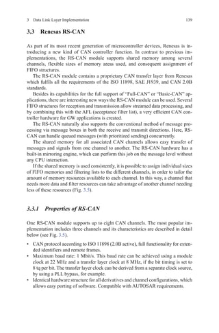
![56 W. Lawrenz et al.
focus on the signal integrity. Analytic considerations and optimization measures
shall give possibilities of a specific judgement and enhancement of the signal qual-
ity of the CAN network.
2.2.1 CAN Network Architecture
Although CAN bus is not one of the high-speed data networks, some phenomena
show that the laws of physics apply here. Especially at speeds above 250 kbit/s and
at cable lengths above 50 m, it must be analysed more closely and will require some
calculation rules. The actual physical properties of the CAN bus lines as well as the
circuitry of the connected control devices have to be considered. If the electrical
specifications of these components are available, the quality of the received signals
can be derived from the transmit signals. To reduce the complexity of calculations,
some assumptions can be made, which are explained below.
Simulations may be used to avoid the need for such calculations. However, fun-
damental knowledge of all influencing parameters is important to predict the impact
of changes or modifications on existing CAN networks.
2.2.1.1 Transmission Line Theory
Theoretical considerations of the electrical lines are based on the electromagnetic
waves forming the signals, which spread along the line with a characteristic speed.
Therefore, voltage and current pulses of CAN messages also move from transmitter
to receivers with a characteristic propagation speed. For very slow operations, i.e.
switching off light, this can be neglected. For the fast CAN signals, the propagation
speed limits the allowable cable length. Signals are classified as fast, if the rise time
is shorter than the propagation time of the corresponding line.
The specific propagation delay results from the material properties of the cable
in use. The dielectric constant of the insulating material and geometric parameters
plays an essential role. Hence, a wave impedance can be determined, which de-
scribes the relationship between current and voltage at any point on the line, and the
propagation speed of pulses on the line. On closer inspection, these parameters are
frequency dependent, which can have an impact on very fast signals (above about
5 Mbit/s). For CAN signals, this effect can usually be neglected. The impedance
thus can be assumed to be a resistance.
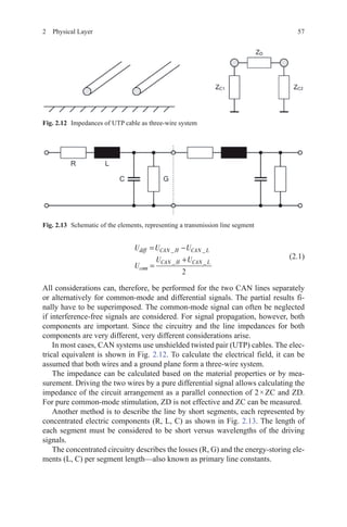
The transmission of CAN signals is usually performed in a differential method.
Two wires are used, where the data signal is derived from the voltage between the
conductors. To simplify the calculation of the transmission signals, the signals of
the two conductors can be decomposed in a differential signal and a common-mode
signal.
The differential signal—also called odd mode signal—and the common-mode
signal can be calculated if the voltage of each single CAN signal line is known, as
shown in [2.1]:](https://image.slidesharecdn.com/1447156129can-150305165128-conversion-gate01/85/1447156129-can-80-320.jpg)
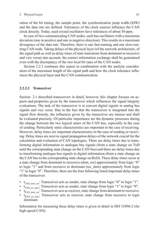
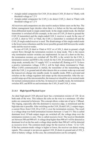
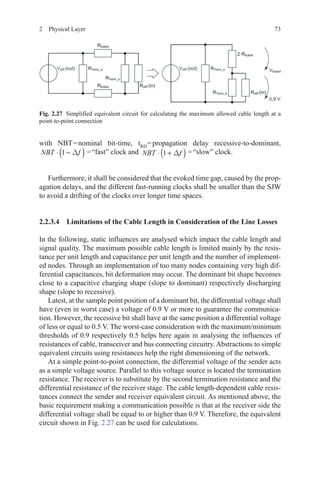
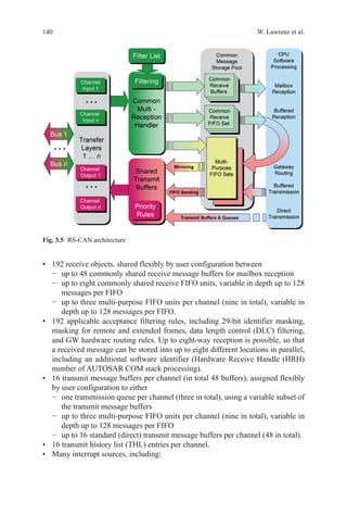
![672 Physical Layer
be as close as the injection location which is normally at the bus connector pins of
the node. Usually, ESD protection components are realized with varistors which
are implemented between the bus signals and GND. Relevant for signal integrity
inspections are the parasitic capacitances which are normally depicted in the data
sheet of the ESD protection component.
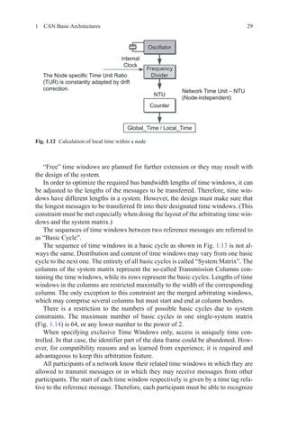
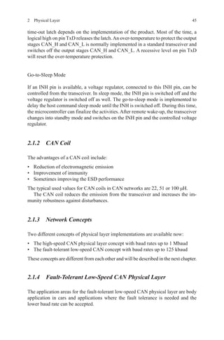
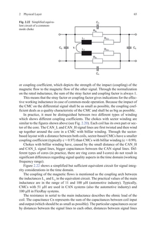
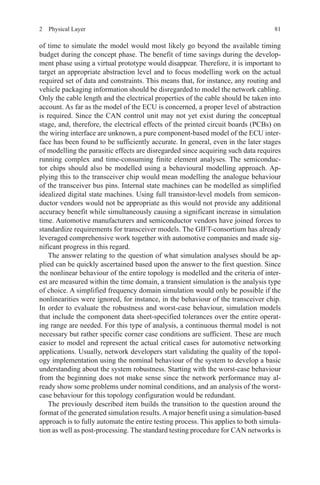
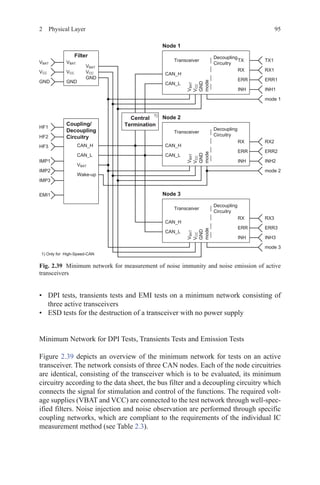
To sum up all components of a CAN node bus connection, Fig. 2.23 implies,
depicted for signal integrity valuations, important equivalent circuit.
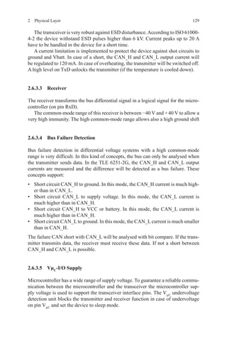
2.2.2.6 Isolation and GND Shift
In case of applications with huge topologies and high current consumptions, GND
shifts (or shifts on the supply line) may occur. In the following, an example case
explains which measures shall be taken into account to avoid influences of the ap-
plication’s current load on the CAN communication. Further praxis-relevant solu-
tion approaches, related to industrial used CAN networks, could be found in the
DeviceNet specifications [ODVA94].
In this example, the CAN nodes have a huge distance to each other and thus
the cable length is relatively long. To illustrate, for example, a CAN control of in-
dustrial motors on a conveyor belt is used. GND line and supply line are installed
together with the CAN lines. In case of a common use of supply and GND lines
for application and CAN communication, the voltage drop over the GND cable
will be dependent on the cable resistance per unit length, the length of the cable as
well as the current load of the application (which could be huge in comparison to
the CAN communication current load). This voltage drop over the GND cable af-
fects as a GND shift which may influence the CAN communication and the related
application.
Fig. 2.23 CAN bus connecting circuit of a CAN node](https://image.slidesharecdn.com/1447156129can-150305165128-conversion-gate01/85/1447156129-can-91-320.jpg)
![692 Physical Layer
2.2.3.1 Ringing at the Transition from Dominant to Recessive
For signal quality evaluations of CAN network topologies, it is crucial to know
where disturbances occur and which properties of the network architecture or prop-
erties of the CAN node architecture amplify these disturbances. In case of signal
integrity evaluation of CAN networks, the state change from dominant to recessive
is of particular importance. Abstracted, it could be said that during the state change
an energy source driving the differential signal is taken from the bus (which results
in the recessive state) and instead a high ohmic receiver circuit is added to the bus.
The existing energy inside the system degrades over the passive components of
the network. Implemented capacitive and inductive energy storages discharge and
influence each other. Recharging between inductive and capacitive stored energy
may occur which results in oscillations of the bus signals which is called ringing.
These overshoots and undershoots occur at different strengths dependent on the
characteristics of the different used components. These interactions can be clarified
by formula [2.2] of the fundamental field of the electro techniques:
u L
i
t
= ·
∆
∆
(2.2)
First, to assume a constant stray inductance, which is operative in the differential
mode, it is easy to see using formula [2.2] that the overshoots and undershoots will
be more intense in case of a transceiver which produces faster slow rates; thus,
the Δi/Δt is higher. Furthermore, different CMCs have different stray inductances.
CMCs with higher stray inductances (smaller coupling coefficients) invoke high-
er overshoots and undershoots. CMCs with sector-based winding have in general
smaller coupling coefficients and approximately higher stray inductances. CMCs
with bifilar winding have in general higher coupling coefficients.
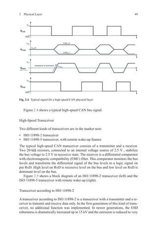
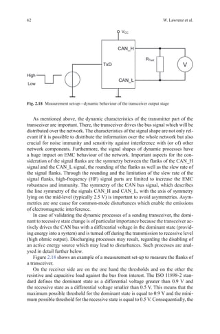
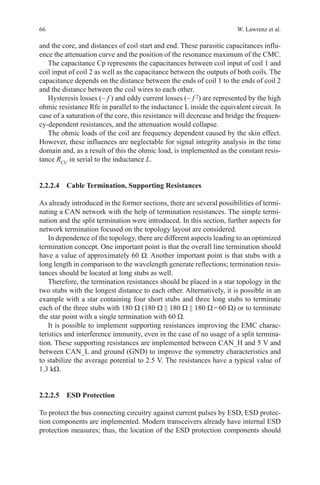
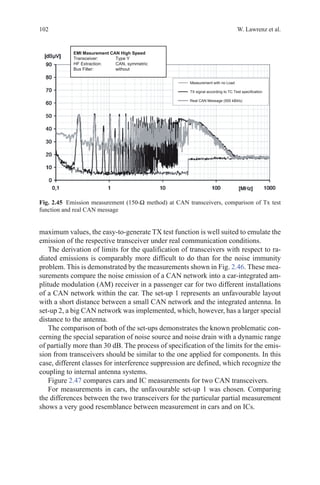
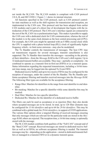
Figure 2.25 compares both extreme cases of these interactions of different com-
ponents. The solid curve refers to a CAN node with a transceiver with a fast slew
rate, corresponding to a high Δi/Δt, and with a CMC with sector winding, thus a
high stray inductance. The dotted line belongs to the same CAN node but in the
case with a transceiver with a slower slew rate while applying a CMC with a higher
coupling coefficient. It is easy to see that the ringing is less intense with the second
equipped case (dotted line). The measured CAN node is located inside a symmetric
CAN topology with two stars where all stubs have the same length to the star points.
This topology is typical for a lot of ringing at the state change from dominant to
recessive caused by the symmetric characteristics which leads to an adding of par-
ticular reflection parts.
As already mentioned, the energy distribution in the system is of importance.
Therefore, two relevant scenarios shall be taken into account: On the one hand, the
signal flow and behaviour at the sending node are important to consider because this
is the point of the energy input. On the other hand, the consideration of the ACK
bit is important. In that case, all receiving nodes start transmitting the dominant](https://image.slidesharecdn.com/1447156129can-150305165128-conversion-gate01/85/1447156129-can-93-320.jpg)

![72 W. Lawrenz et al.
the signal amplitude where the limitation is that at least the threshold for the domi-
nant state shall exceed overall the network independent of the sender’s position.
Data rate and bit timing are influenced by the cable length-dependent delay times.
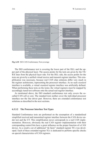
The section “CAN bit timing and oscillator tolerances” already described the
appearance of different fast-running nodes inside a CAN system. In this section,
differences of oscillator tolerances and how they influence the CAN physical layer
are discussed.
An example shall show how the CAN physical layer and bit timing configuration
interfere with and limit each other. For this, the communication flow is analysed
over the time space between two soft-synchronization events.
At the time of the first soft-synchronization (a slope from recessive to domi-
nant), the communication nodes synchronize its clock to the bus signal. From now
on until the next synchronization event, all timing-dependent influences shall be
considered. These influences are mainly delay times of the communication control-
ler and the transceiver at sender and receiver and eventually further components in
the signal flow as well as differences in the node clocks. In addition to this, there
are the propagation delays of the cable which depend on the propagation speed and
the cable length. These delay times occur at the first considered slope as well as the
second considered slope. The basic condition for a successful communication is that
each bit is sampled correctly at the position of the sample point.
The sample point can be shifted to a later position to enable long cable distances.
Thus, a longer time period from the beginning of the bit to the sample point is pro-
vided to allow enough time for all the delay times. However, the margin for com-
pensating clock differences is limited by shifting the sample point to a later position
because with it the SJW size is limited as well.
It is possible to construct worst-case scenarios where two nodes are considered
which have a huge distance to each other and are operating on opposite boundar-
ies of possible clock ranges. In this case, the sending node has a fast clock and the
receiving node has a slow clock. During a long period without synchronization,
the receiver sampling will fall behind the transmitter. The deviation increases
with the difference of the clock rates and with the duration since last resynchro-
nization. The margin for propagation delay times narrows in dependence of the
oscillator times.
Based on an error-free communication scenario, time spaces without resyn-
chronization are limited by the bit stuffing rule. A simple example can be derived
with five dominant bits followed by a recessive stuff bit followed by four recessive
bits—a time space of 10 bits without resynchronization. For error-free communica-
tion, it is required that the slower receiver (propagation delays of the network have
to be considered as well) has to sample the tenth bit as recessive. Therefore, the
following inequation can be derived [2.3]:
10 1 10 1 1⋅ ⋅ −( ) + ⋅ ⋅ +( )− ⋅ +( )NBT f t NBT f fRD
∆ ∆ ∆Phase_Seg2(2.3)](https://image.slidesharecdn.com/1447156129can-150305165128-conversion-gate01/85/1447156129-can-96-320.jpg)
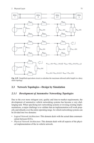
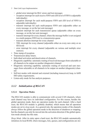
![74 W. Lawrenz et al.
It is possible using the voltage divider formula to calculate the maximum allowed
cable resistance (and with it the maximum allowed cable length) under the con-
sumption that the voltage drop over the receiver resistances is 0.9 V or higher [2.4]:
R
V
V out
R
V
V out
Kabel
Kabel
diff
Term b
Kabel
diff
max
_
=
( )
⋅
−
( )
1
⋅ 2
(2.4)
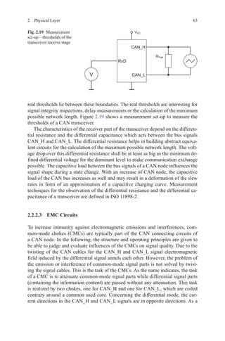
Considering a star topology, the resistance arrangement and with it the simplified
equivalent circuit change to that shown in Fig. 2.28.
At a daisy chain topology, thus a linear topology with stub length of 0 m, an
iterative calculation helps calculating the maximum allowed cable length as shown
in Fig. 2.29.
Fig. 2.28 Simplified equivalent to calculate the maximum allowed cable length of a star
topology](https://image.slidesharecdn.com/1447156129can-150305165128-conversion-gate01/85/1447156129-can-98-320.jpg)
![112 W. Lawrenz et al.
If the WUF-detection unit is not able to detect the CAN frames correctly, i.e. if
more than 32 frames were not correctly detected, the new error counter-sets the
transceiver into PN_Trx_Standby mode.
2.5.4 Transceivers for CAN Partial Networking (ELMOS)
The partial network operation presented here is an integral part of a large number
of possible solutions the automotive industry pursues in order to reach the overall
target for an average CO2
emission of 120 g/km in 2015 as defined by the European
Union (EU).
The most substantial contributions to CO2
reduction are expected from measures
focusing on engine and powertrain as well as from modifications in design and con-
struction. Examples for engine-related measures are, among others, the improve-
ment of conventional combustion engines, the needs-tailored control of ancillary
units and the increased use of hybrid and electric drives. With respect to powertrain,
the use of modern transmissions with six or seven gears is among the measures that
can help realize the reduction of emissions. Moreover, CO2
reduction is possible by
changes in construction and chassis through the use of lightweight structures and
aerodynamic improvements. All these approaches have a direct effect on CO2
emis-
sion as recorded in the New European Driving Cycle (NEUDC). In contrast, the
so-called complementary measures such as a gear-changing timing indicator, an ef-
ficient air conditioning, tyre pressure monitoring systems and smooth-running tyres
are not directly taken into account by test cycle. Although they are credited with up
to 10 g CO2
/km extra, they do not fully cover the reduction potential of efficient
technologies that are beyond the test cycle. Further measures with an effect on the
vehicle, the so-called eco-innovations, are therefore additionally added towards the
target fulfilment of the manufacturer, on the amount of their minimum contribution
yet with no more than 7 g CO2
/km.
In order to raise the potential of the above-mentioned measures, innovations in
automotive electronics are necessary to a large extent. A case in point, it has been
presented in [HUDI09] that operating currents can be reduced by up to 5.7 A with an
energy-optimized E/E-architecture, equivalent to the reduction of CO2
emission by
1.7 g/km in the real customer cycle. With an emission reduction potential of approxi-
mately 0.04 g CO2
/km per control unit and with more than ten control units per vehi-
cle suitable for partial networking, this network operation mode as introduced in the
previous chapter represents an eco-innovation with a high potential in this context.
2.5.4.1 Requirements for High-Speed CAN Partial Networking
In view of the intended levy of 95 € per gram of CO2
beyond the limit [EC09], it
is understandable that eco-innovations such as CAN partial networking are cur-
rently in the focus of vehicle manufacturers. Within the framework of a working](https://image.slidesharecdn.com/1447156129can-150305165128-conversion-gate01/85/1447156129-can-136-320.jpg)
![1132 Physical Layer
group initiated by the Verband der Automobilindustrie, VDA), an ideas competi-
tion was launched by the German automakers, calling on semiconductor vendors
to present their solutions for the support of this kind of partial network operation
by a transceiver. The results were pooled in a requirement specification docu-
ment [OEM11]. From the very start, however, this VDA working group had the
stated goal to establish an international standard rather than a proprietary solution.
For this reason, experts from automakers and semiconductor vendors worked to-
gether under the roof of the so-called selective wake-up interoperable transceiver
in CAN high-speed (SWITCH) group in order to prepare the standard proposal
ISO/NP 11898-6 “Road vehicles—Controller area network (CAN)—Part 6: High-
speed medium access unit with selective wake-up functionality”. This proposal
has been forwarded to the ISO for decision and is currently in the stage “new
project approved”.
The essential outcome of the standardization efforts of the VDA working group
and the SWITCH group so far is that partial network operation will be realized by
selective wake-up of ECUs in partial network mode with the help of individual
WUFs. The WUF is a valid CAN data frame in accordance with ISO 11898-1.
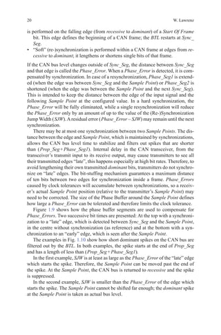
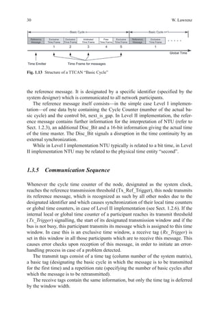
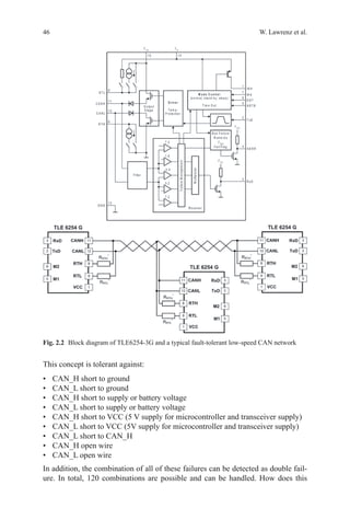
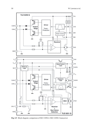
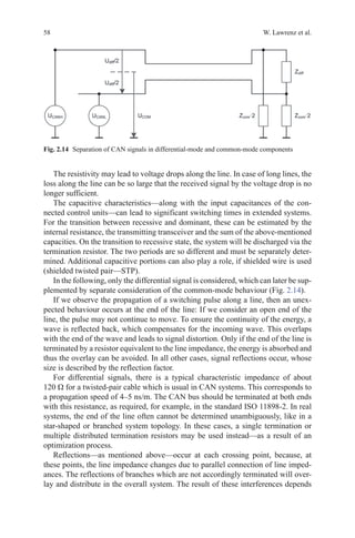
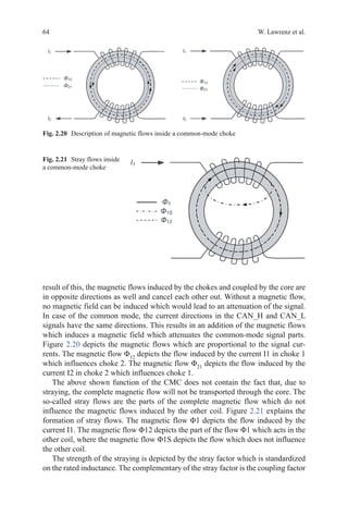
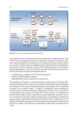
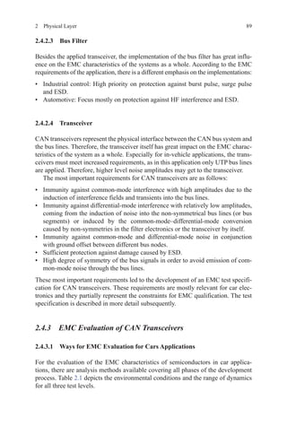
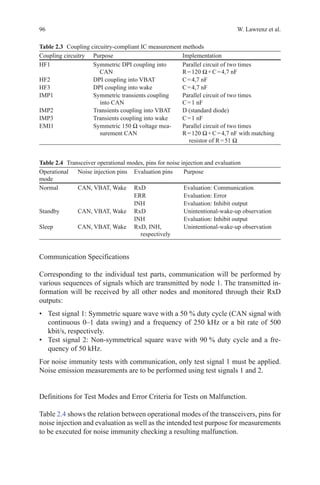
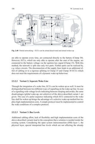
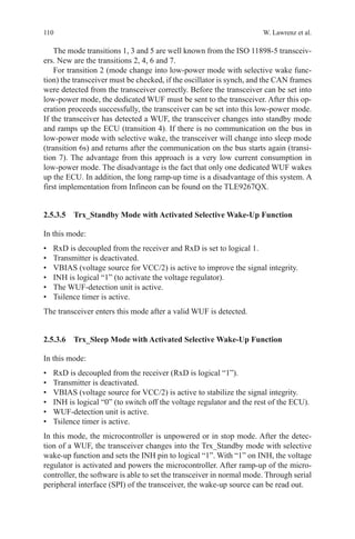
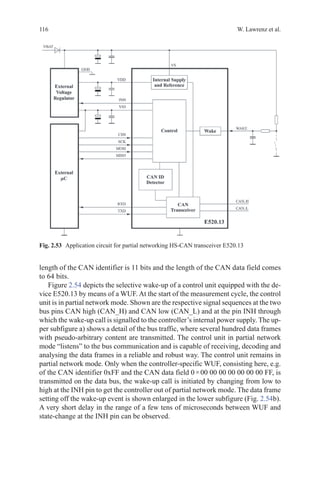
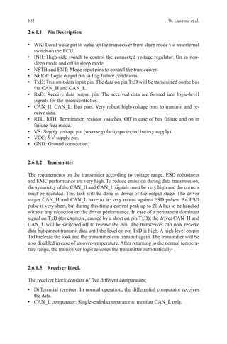
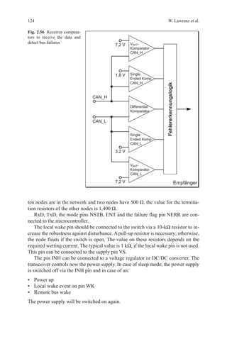
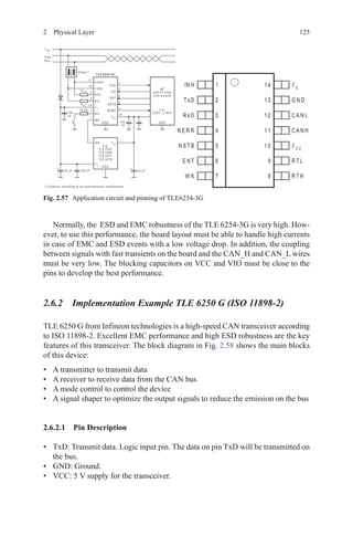
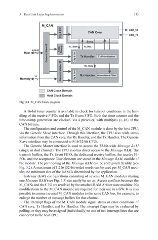
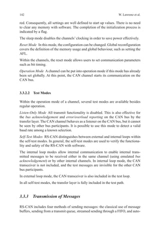
Figure 2.51 depicts a generic ECU in active mode.Atypical current consumption
of such a control unit can be several 100 mA.
The challenge is to minimize the current consumption of such a control unit
while providing for selective wake-up capability via the data bus at the same time.
One reasonable approach involves the implementation of the necessary additional
functions for partial network operation in the transceiver as this device is the link for
the connection between the control unit and the vehicle’s data bus. If the transceiver
is supplied directly by the battery in partial network mode, as is common practice
today in sleep mode, all other components of the control unit can be deactivated.
Therefore, this approach is distinguished by higher energy saving potential when
compared to the implementation of partial network operation, for example, in the
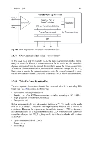
microcontroller. The control unit in partial network mode is depicted in Fig. 2.52,
indicating inactive functional blocks in grey.
The transceiver now “listens” to the data bus and analyses the bus traffic. Once
the WUF, the individual message for the respective control unit, is detected on the
Fig. 2.51 Generic electronic control unit in active mode](https://image.slidesharecdn.com/1447156129can-150305165128-conversion-gate01/85/1447156129-can-137-320.jpg)


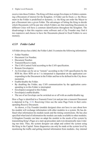
![2054 Higher Level Protocols
to the correct interface function. In this example, it is called the CanIf_Transmit
function.
CanIf_Transmit(CanTxPduId, pPduInfoPtr);
4.2.3.7 CAN Interface
The CAN interface is the last hardware-independent module in theAUTOSAR-layered
architecture; it has the job to connect the hardware-dependent CAN driver. The CAN
interface gets the PDUs from the above layers, adds the data the CAN driver needs
and implements buffering functions (if the hardware is occupied) and acknowledge-
ment functions for the send and receive signalling. Furthermore, the CAN interface
controls the operating modes of the CAN controller (sleep mode and error modes) and
signals changes of these modes to the higher layers (wake-up and bus-off).
The function CanIf_Transmit, which is called by the PDU router, takes the cor-
responding configuration for the given PduId and calls the CAN driver. The mini-
mal configuration-related information is, for example, on which CAN channel the
message shall be sent and which CAN ID shall be used. After assembling these
data the driver function is called. It is possible that the CAN interface is able to call
several drivers—e.g. if an external CAN module is used. In general, the on-chip
CAN modules will be supported by one single CAN driver; hence, the use case with
several CAN drivers is rare. The CAN driver function gets as parameter the unique
hardware transmit handle ( Hth) and a pointer to the data structure PduInfo, where
the CAN ID, DLC and a pointer to the payload data are stored.
Can_Write(CanIf_CTxPdus[txPduIndex].hth, canPduInfo);
4.2.3.8 CAN Driver
The CAN driver is the last piece of the communication path of an AUTOSAR com-
pliant software platform. The driver initializes the register of the CAN module with
correct values and sets the right bits for actions or data transfer. The access to these
control and data registers will be provided by standardized functions to the higher
software layers. Another important functionality is the implementation of all inter-
rupt service routines Receive (Rx), Transmit (Tx), error, etc.). The driver receives
the data to be transmitted by the CAN interface, copies it into a hardware-mailbox
of the CAN controller and triggers the sending process. In the opposite direction,
the CAN driver signals the reception of a new CAN message via callback mecha-
nism, e.g. triggered by the receive interrupt.
Today’s CAN controller provides complex, intelligent mechanisms implemented
in hardware, for example, FIFO buffering or filtering mechanisms. Universal drivers,
easy to port and maintainable on various hardware platforms, use these hardware func-
tions not very often. For example, FIFO buffering implemented in software is not effi-](https://image.slidesharecdn.com/1447156129can-150305165128-conversion-gate01/85/1447156129-can-228-320.jpg)
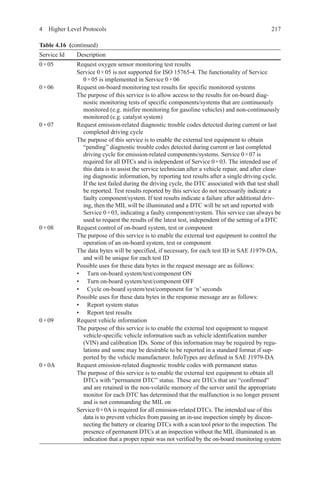
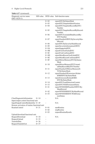
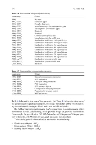
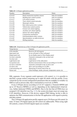
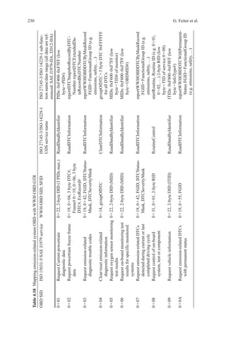
![224 G. Feiter et al.
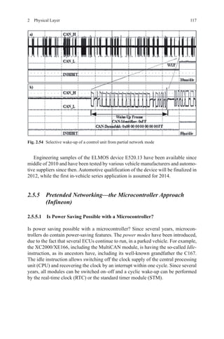
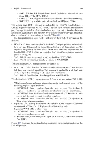
– Clear identification of the class of each malfunction, i.e.:
○○ Hierarchical safety-related malfunctions.
○○ Malfunctions that result in pollutant emissions exceeding a pre-set legisla-
tive threshold.
○○ Malfunctions that do not result in pollutant emissions exceeding a pre-set
legislative threshold, but which could result in pollutant emissions exceed-
ing a pre-set legislative threshold at some time soon.
○○ Malfunctions that do not need to be covered by legislation but are neces-
sary for an efficient diagnostic and maintenance function.
– Ability to communicate ‘readiness’ data to confirm if the vehicle is ready to
be inspected and has not had its fault memory cleared recently 1 (e.g. key
starts/warm-up cycles/distance travelled since memory cleared, how many
diagnostics have run and been completed, ability to see if a previously active
fault has been cleared by a scan tool but not fixed).
– Ability to transmit roadworthiness-related fault information (e.g. malfunction
indicator (MI) status and MI commanding ‘on’ fault codes, odometer read-
ings, distance travelled with MI on, emission “severity/priority” of fault).
– Ability to transmit vehicle identification information 1 (e.g. vehicle identifi-
cation number (VIN), software version, odometer reading, engine ID, trans-
mission ID, vehicle weight rating/class information).
– Ability to help combat tampering 1 (e.g. unauthorized clearing of diagnostic
information).
– Ability to help identify tampered or corrupted software at the time of
inspection.
– Ability to help identify (potentially) tampered hardware at the time of
inspection.
– Ability to identify and retrieve roadworthiness-related information from all
electronic control modules (ECM, TCM, etc.) through a single process and by
wireless connection.
– Compatibility with I/M equipment ([connector], hardware, software etc.).
– Additional specific inspection needs (e.g. mode $ 08-type commands for
smoke opacity test etc.).
– Compatibility with potential future telematics-based vehicle systems, e.g.
bluetooth, IEEE 802.11b (or later specification).
4. Needs for the technician (i.e. repairer, replacement part maker, tool maker, etc.)
are as follows:
– Data update rates (e.g. how fast can real-time sensor data be displayed for
technicians, communication speed, ability to obtain multiple PID’s with sin-
gle requests etc.).
– Access to established and extendable to non-established chassis control
related fault codes and real-time data in a standardized manner.
– Mode $ 06 test results (data available in a standardized, understandable for-
mat without need to refer to a service book).](https://image.slidesharecdn.com/1447156129can-150305165128-conversion-gate01/85/1447156129-can-247-320.jpg)

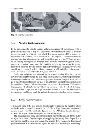
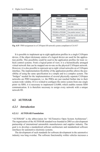
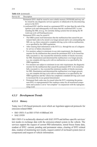
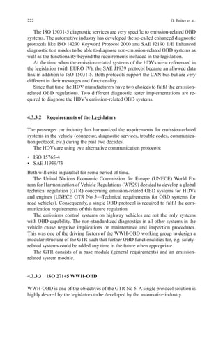
![2715 Applications
surpass the existing architecture while keeping development and purchasing costs
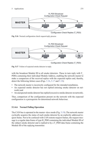
at a comparative level.
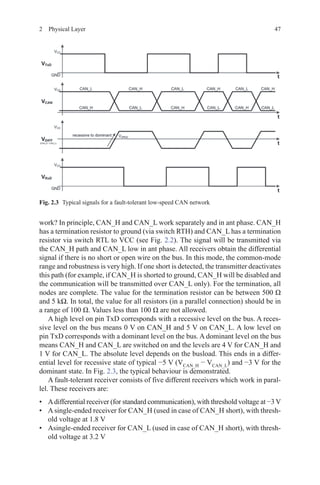
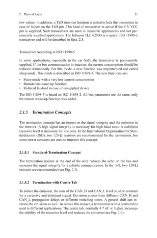
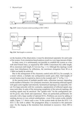
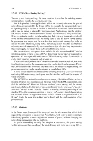
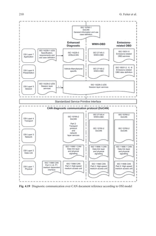
The latter was feasible by reusing the existing smoke detector core and fitting it
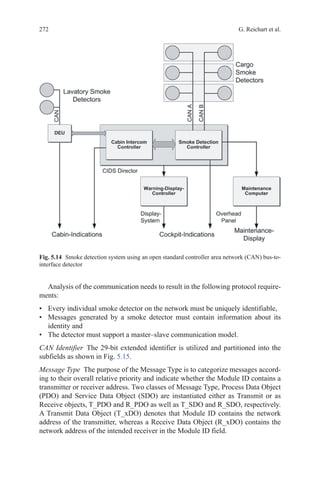
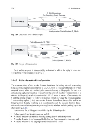
with an altered communication and power interface (see Figs. 5.13 and 5.14).
The communication medium had to meet a number of requirements for eligibil-
ity in a safety-critical application:
• Advanced data integrity and error detection features,
• Deterministic behaviour,
• Operability in challenging EMC environments and
• High degree of flexibility in choice of network size and topology.
Considering the 30-year design life of a modern passenger aircraft, the long-term
availability of electronic components was scrutinized in order to minimize the risk
of equipment redesign resulting from component obsolescence throughout the life
cycle of the aircraft.
The CAN bus was deemed the most suitable communication medium capable of
fulfilling the above requirements.
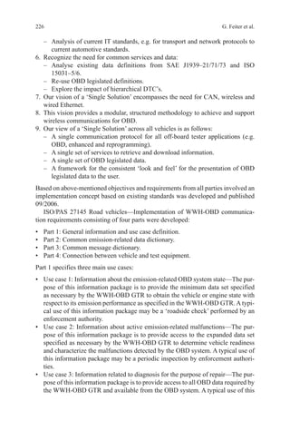
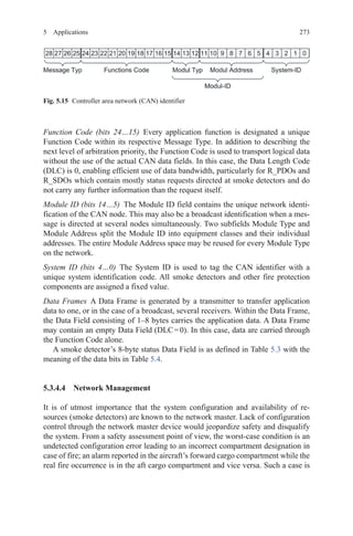
5.3.4.3 Protocol
The CAN protocol, as defined in ISO 11898 [ISO11898], covers layers 1 and 2 of
the OSI communication model. The remaining layers, up to layer 7, have to be man-
aged by additional services up to the application. Various standardised higher layer
protocols such as CANopen are available and widely used in industrial applications.
Instead of selecting a generic high layer protocol, a specific to-type application
layer protocol was developed and documented in a System Interface Document
[SCHMID] in order to ease compliance with RTCA/DO-178 [DO178B] guidelines.
Fig. 5.13 Smoke detection system using proprietary detector supply and communication loop](https://image.slidesharecdn.com/1447156129can-150305165128-conversion-gate01/85/1447156129-can-294-320.jpg)
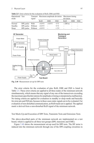
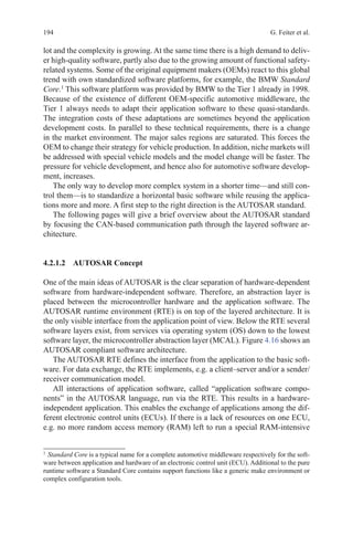
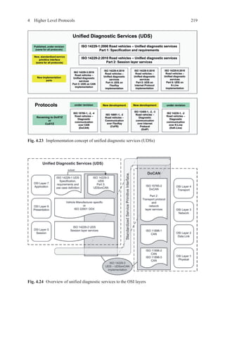
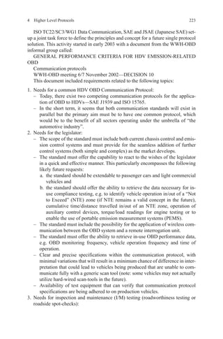
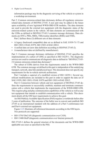
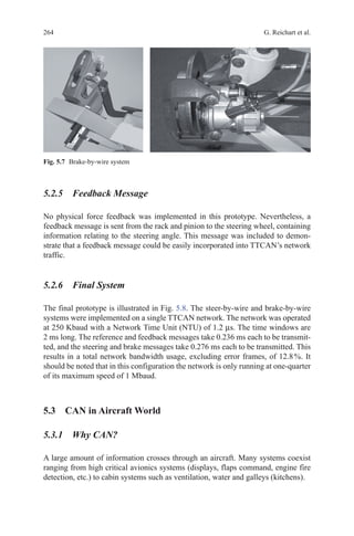
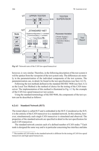
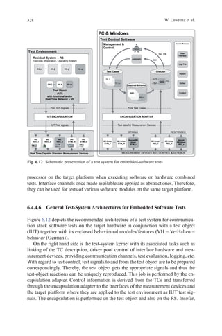
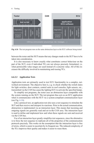
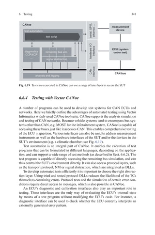
![2856 Testing
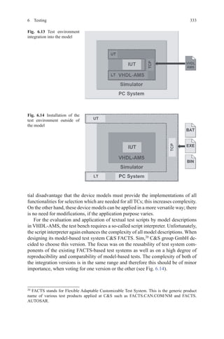
certain requirements may become an important issue, referring to the previously
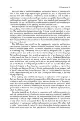
mentioned step (see Fig. 6.1).
The implementation of component specifications may include (unfavourable)
misinterpretations and “real” mistakes. If a mechanism was not understood in the
same way as originally intended, it may be difficult to call it a mistake. A specifica-
tion may lead to a logically correct conclusion, which, simply said, had not been
intended by the designer. Nevertheless, the major goal must be kept in mind that
products of different suppliers shall be sufficiently compliant and in accordance
with the standard.
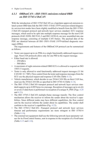
6.1.1 Important Terms
• Conformance
According to ISO 9000 (see [ISO9000], §§ 3.6.1, 3.8), conformance corresponds to
“fulfilment of a requirement”, while a mistake is “non-fulfilment of a requirement”.
Furthermore, this standard emphasizes testing as an appropriate means for objec-
tive proof of conformance. An implementation is proven to be conformant if it is
compliant to all specified requirements.
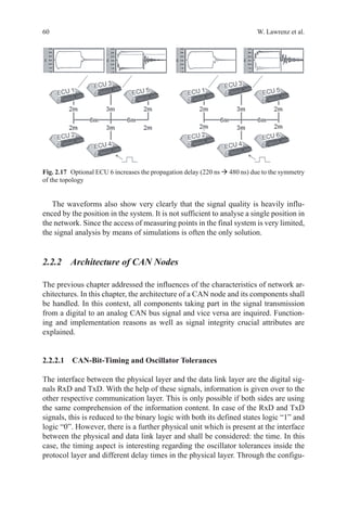
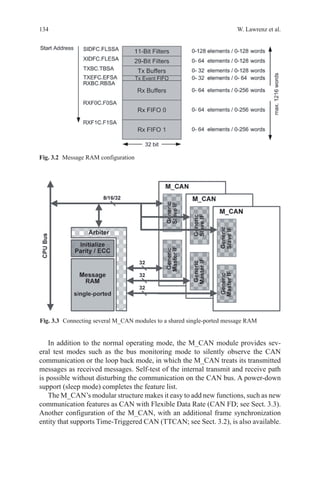
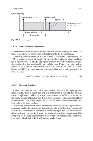
• Conformance Tests
Conformance tests check the behaviour of an implementation against the corre-
spondingly specified standard. These tests are functional tests, belonging to the
group of dynamic test methods (see Fig. 6.2).
Fig. 6.1 Deviation of specification and implementation of components](https://image.slidesharecdn.com/1447156129can-150305165128-conversion-gate01/85/1447156129-can-308-320.jpg)
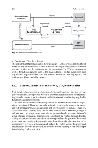
![2896 Testing
specifications. As such, a component specification could define a component which
is not interoperable with other components of its kind.
An undiscovered error in the component specification could result in compo-
nents conforming to the specification but, nevertheless, not working appropriately.
As such, the quality of implementations not only depends on the coverage and ex-
cellence of the conformance tests, but also depends significantly on the quality of
the component specification itself. This specification is responsible for the defini-
tion of a component with an appropriate functionality corresponding to the system
requirements. Failing this, the conforming implementations could not operate ap-
propriately as this was a contradiction to the specification.
As for the end customer, finally interoperability is the utmost goal; they mostly
require tests proving interoperability. However, this cannot be achieved by mere
testing. Nevertheless interoperability tests do exist, mostly connecting various im-
plementations under laboratory conditions resulting in the verdict “OK” or “NOT
OK”, when applying specific test scenarios. The value of this verdict, however, is
rather limited with respect to the applied test scenarios, as due to this concept, tech-
nically and practically it is not feasible to check any possible scenario. As such, any
effort claiming to guarantee interoperability by testing is dubious.
Assuming a specification is properly done, in general, the risk of non-interop-
erable specified components is low. Consequently, the chance for interoperability
is increasing with the degree of compliance between the implementation and its
specification. The compliance is proven by conformance tests.
As mentioned above, the quality of the specification is supported by develop-
ment of conformance tests while precisely analysing the component specification
and pushing for its non-ambiguous interpretation. As such, a high-quality compo-
nent specification and related conformance tests will result. The risk of non-interop-
erable components is estimated to be rather low, especially when findings from the
development of the conformance tests are fed back into the subsequent revision of
the component specification resulting in non-ambiguous statements. Unfortunately,
the constructive feedback very often does not quite easily have its effect, because
standards quite often rather quickly become “untouchable”.
In conclusion, conformance tests as well as any other tests cannot guarantee
absolute interoperability, but they increase the chance to it.
6.1.3 Test Methods, Test Standards and Test Rules
Various test objects require different implementations of test systems, especially
related to the coupling of the test object to the test system. Most of the test systems
are based on the principle of accumulating findings from experience in order to
come to better solutions. Many of the characteristics, excellence and advantages of
existing test systems can be transferred to other test systems.
The standard ISO 9646 (see [ISO 9646]) specifies conditions and the methodol-
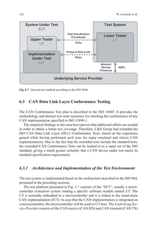
ogy for the design and execution of conformance tests according to well-defined](https://image.slidesharecdn.com/1447156129can-150305165128-conversion-gate01/85/1447156129-can-312-320.jpg)
![296 W. Lawrenz et al.
memory, but this cannot be accomplished anticipatorily. Obviously, first the error
must be stimulated and then subsequently the error memory can be read in order
to perform the error-detection check. Additionally the entry must not be persistent.
A simple trial-and-error process to check whether a TC with a test pattern can be
successfully applied is not suited for a validation process. If, as described above, a
test does not adhere to an appropriate sequence of test steps or initial states are not
checked, tests erroneously may lead to a “fail” or “pass” verdict. Referring to the
example, a standard conforming implementation erroneously would result a “fail”
only because the error memory would not yet have stored the expected error when
reading the error memory. Vice versa, there are cases in which wrong implementa-
tions may erroneously be judged as conforming implementations. Referring to the
above example, this would be the case, if the erroneous test object would perma-
nently indicate an error and the tester would not check the—wrong—initial state.
A validation must prove that such kinds of errors do not exist and that only a
conforming behaviour of a test object results in a “pass” verdict. In order to meet
the process requirements of ISO/IEC 17025 (see [ISO17025]), a technically appro-
priate and fully documented validation of a test system is a condition sine qua non,
which nevertheless corresponds to a rather high quality level.
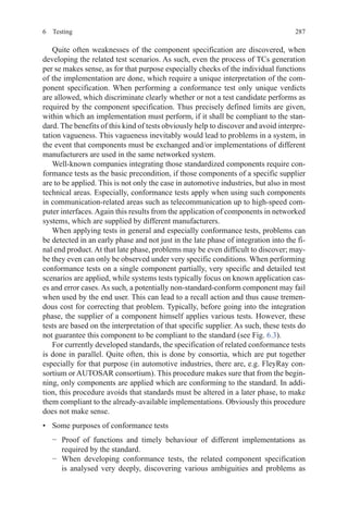
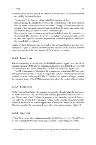
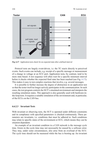
6.2 CAN Transceiver Conformance Tests
This section addresses the testing of controller area network (CAN) transceiver.
They are a part of the CAN physical layer. The general standardization of CAN has
already been described in earlier sections. In Sect. 6.2.1, first the standardization of
physical layer of CAN will be discussed. Section 6.2.2 gives an introduction to why
it is necessary to submit systematic tests to the CAN transceiver before their use
in real applications. Subsequently, the test idea underlying the tests is presented in
terms of test method and test principle in Sect. 6.2.3. The structure of the test system
is described in Sect. 6.2.4. At the end of this section, the TCs and their focal points
for different CAN transceiver implementations are described in Sect. 6.2.5.
6.2.1 Standardization of the Physical Layer of CAN
For a general history and standardization of CAN, see the sections before.
The parts 2, 3 and 5 of the ISO 11 898 are the relevant standards of the CAN
physical layer and are briefly introduced below.
ISO 11898-2: High-speed, medium-access unit The standard ISO 11898-2 is the
most implemented standard of CAN physical layer. It describes the functional1
and physical2
interface to the transmission medium. Also, the specification of the
1
Functional interface: Medium-Dependent Interface (MDI).
2
Physical (electrical, optical) and mechanical interface: Physical Medium Attachment (PMA).](https://image.slidesharecdn.com/1447156129can-150305165128-conversion-gate01/85/1447156129-can-319-320.jpg)
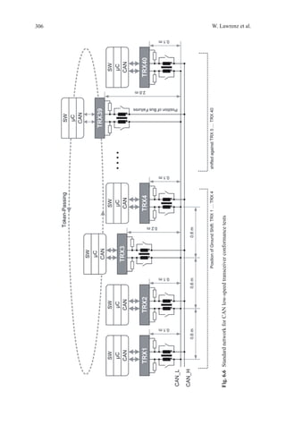
![298 W. Lawrenz et al.
The first step on the way to a desired interoperability of CAN modules from dif-
ferent manufacturers in a CAN bus system was so taken with the publication of the
standard ISO 11898.
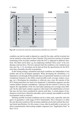
6.2.2.2 Risks of Complex Bus Systems
Due to the use of CAN in exceedingly complex and safety-related systems, a use
of CAN modules without prior checking is not feasible. Several risk factors can
restrict the proper communication between the CAN modules in such a significant
way that the entire bus system is no longer able to fulfil its function:
• Faults in the implementation: Standardized interfaces are only the “outside”, but
not the realization of the implementation. By implementing this freedom, can
faults be built into a device, at which the blur of interpretation3
has an important
part? Especially those errors which lie in the blur of interpretation may not be re-
cognized in the accompanying development tests. Errors in the implementation
are often only seen when the module is embedded in its real environment with
all its influences and interactions.
• Interdependence of a module with its environment: The interdependence of a
module with its environment is one of the most common sources of faults in a
bus system. The networks themselves and their tasks are characterized by a very
large and still growing complexity. Therefore runs the number of possible events,
event sequences and combinations of events that result from the interaction of
the various components and the effects of component and network environment,
gets very large indeed. Thus, the probability is very low that in the specification
of the module all requirements are defined, which result from later applications.
• Gaps or errors in the underlying implementation of a standard: Information ab-
out the first publications of the ISO 11898 standards can be found at [CIA10] the
citation “[….] the ISO standard 11898 for CAN was published in November of
1993. [….] Unfortunately, all published CAN specifications and standardizati-
ons contained errors or were incomplete”. These early times are long gone, yet
gaps can occur in a standardized specification or subsequently become relevant.
During the development of a specification, the boundary conditions of the sub-
sequent use of the object of specification are often not considered or considered
just insufficiently. The reason for this lies mainly in the fact that not all later
applications are known and can be known. The type and depth of the aforemen-
tioned interdependence of a module with its environment are often ignored when
creating the specification. The development of a test specification is therefore
always a kind of “test for completeness” of the relevant product specification.
3
According to Sect. 6.1, blur of interpretation means: in the interpretation of a specification for
the purpose of implementation, small deviations between the intended content of specification
(goal of the author) and implementation (interpretation of converter ligands) can occur.](https://image.slidesharecdn.com/1447156129can-150305165128-conversion-gate01/85/1447156129-can-321-320.jpg)
![330 W. Lawrenz et al.
borderline cases, which are difficult to implement in the physical world. Such a re-
alistic worst case scenario, for instance, is the network topology layout of networks,
whereas one control unit under the hood may operate at + 100°C while another
one in the trunk may be at −40°C. Different environmental temperatures influence
significantly the operation characteristics of the corresponding physical bus drivers.
Simulating such a scenario only under the assumption of typical or almost ideal
environmental conditions bares a high risk for corrupted signal integrity and finally
for the safe operation of the whole end product as well. On the other hand, simula-
tions can easily consider tolerances of the physical bus drivers as well. Topologies,
therefore, can be analysed in high-frequency range as well as charged with non-
typical loads in order to generate borderline cases. Among others, the number of
nodes applied in a topology has great influence, because not only the bus drivers but
even the chosen bus lines influence the signal quality.
In order to meet the requirements for high-quality tests correspondingly, ap-
propriate models supplied by the component manufacturers are required. Unfortu-
nately, thereof the first area of problems arises: As there is no standardized valida-
tion method, there is no way to check these models for compliance to the require-
ments of the standard. Furthermore there is no compatibility among the different
languages which are applied for model specification. On one hand, there is the
traditional language SPICE14
which unfortunately is not well suited for generat-
ing more complex models such as for bus drivers. SPICE quite obviously has its
weaknesses when functional or behavioural descriptions are required. On the other
hand, non-open specified description languages are applied; one of them is MAST,
a proprietary language. That is why, there is a certain interest to create standards for
generic and specific requirements on models, requirements on simulation environ-
ments and requirements on model test specifications. Only when following this
path independently, reproducible and comparable test results and a corresponding
quality evaluation on model basis can be achieved.
Subsequently, a model-based test method is presented. This test method not only
is well suited for checking transceiver implementations against their existing stan-
dards, but also can be applied to check the overall physical network with special
focus on the integrity of signals on the communication media. As such, two major
aspects with regard to analysis of the signal integrity are met: on one hand the vali-
dation of individual components and on the other hand the observation and evalua-
tion of a complex topology.
6.5.1 VHDL-AMS
VHDL-AMS (Very High Speed Integrated Circuit Hardware Description Language - Analog
and Mixed Signals) is an extension of VHDL (see [IEEE1076]) for simulation support
of digital, analog and mixed signals systems and technologies. VHDL AMS allows
14
Simulation Program with Integrated Circuits Emphasis—there are optimized and commercially
available versions such as PSPICE or HSPICE.](https://image.slidesharecdn.com/1447156129can-150305165128-conversion-gate01/85/1447156129-can-353-320.jpg)
![345W. Lawrenz (ed.), CAN System Engineering, DOI 10.1007/978-1-4471-5613-0,
© Springer-Verlag London 2013
Bibliography
[AUTO01]AUTOSAR GbR,AUTOSAR erreicht ersten Meilenstein—Erste Spezifikationen werden
veröffentlicht, Pressemitteilung, 2. Mai 2006, URL: www.autosar.org, Home Media Media
Releases
[CIA10] CAN in Automation (CiA): URL: http://www.can-cia.org, 2010 Home Device design
Technology CAN CAN history
[CSG10] CS group GmbH: URL: http://www.cs-group.de, 2010 Home ConformanceTests CAN
osi-1 CAN OSI1—Tested Products
[DO178B] Radio Technical Commission for Aeronautics (RTCA), DO-178B Software Conside-
rations in Airborne Systems and Equipment Certification, RTCA, Washington D. C., 1. Dez.
1992
[ETEM02] Berufsgenossenschaft Energie Textil Elektro, Grundsatz für die Prüfung und Zerti-
fizierung von „Bussystemen für die Übertragung sicherheitsrelevanter Nachrichten“, Fachaus-
schuss Elektrotechnik, Mai 2002 URL: http://www.bgetem.de/praev/praev_pruefgrundsaetze.
html
[HEUR06] Heurung T (2006, 20. März) In-vehicle network design methodology, 2nd IEE Auto-
motive Electronics Conference. The IEE, Savoy Place, London
[HUDI09] Hudi R (2009, 15.–16. Juli) Die E/E Entwicklung im Wandel auf dem Weg zur Elektro-
mobilität, Automobil Elektronik Fachkongress Elektronik, Ludwigsburg
[IEEE1076] IEEE 1076, VHDL Language Reference Manual, IEEE, 2009 ISBN: 978-0-7381-
5801-3
IEEE 1076.1, VHDL Analog and Mixed-Signal Extensions, IEEE, 2007 ISBN: 0-7381-5627-2
[ISO9000] DIN EN ISO/IEC 9000 (2005) Qualitätsmanagementsysteme—Grundlagen und
Begriffe, ICS 01.040.03, ICS 03.120.10, ISO
[ISO9646] ISO/IEC DIS 9646-1 … 7 (1994–1998) Information technology—Open Systems
Interconnection—Conformance testing methodology and framework, ICS 35.100.01, ISO
[ISO11898] ISO, Road vehicles—Interchange of digital information—Controller area network
(CAN) for high-speed communication, ISO, 1993 (zurückgezogen, revisioniert durch ISO
11898-1:2003 und ISO 11898-2:2003)
ISO 11898-1 (2003) Road vehicles—Controller area network (CAN)—Part 1: Data link layer and
physical signalling, ISO
ISO 11898-2 (2003) Road vehicles—Controller area network (CAN)—Part 2: High-speed me-
dium access unit, ISO
[ISO16845] ISO 16845 (2004) Road vehicles—Controller area network (CAN)—Conformance
test plan, ICS 43.040.15, ISO
[ISO17025] DIN EN ISO/IEC 17025 (2005) Allgemeine Anforderungen an die Kompetenz von
Prüf- und Kalibrierlaboratorien, ICS 03.120.20, ISO
[KRUE08] Krüger M (2008) Grundlagen der Kraftfahrzeugelektronik—Schaltungstechnik, 2nd
edn. Hanser Verlag, München](https://image.slidesharecdn.com/1447156129can-150305165128-conversion-gate01/85/1447156129-can-367-320.jpg)
![Bibliography
[LUEB04] Lübke A Car-to-Car Communication—Technologische Herausforderungen. In: VDE-
Kongress 2004, Innovationen für Menschen, Band 2: Fachtagungsberichte DGBMT, GMM,
GMA, VDE Verlag, Berlin
[MOST06] MOST—Media Oriented Systems Transport, Multimedia and Control Networking
Technology, MOST Specification. Revision 2.5, MOST Cooperation, Oktober 2006
[MYER89] Myers GJ Methodisches Testen von Programmen, 3nd edn. Oldenbourg Verlag, Mün-
chen, 1989 ISBN-10: 3-486-21317-2, ISBN-13: 978-3-486-21317-1
[ODVA01] ODVA, CIP Networks Library, Volume 1, Common Industrial Protocol, Edition 3.7,
© 2001 bis 2009, ODVA, Inc., November 2009
[ODVA05] ODVA, CIP Networks Library, Volume 5, CIP Safety, Edition 2.2, © 2005 bis 2009,
ODVA, Inc., May 2009
[ODVA94] ODVA, CIP Networks Library, Volume 3, DeviceNet Adaptation of CIP, Edition 1.8,
© 1994 bis 2009, ODVA, Inc., November 2009
[OEM10] Audi, BMW, Daimler, Porsche, Volkswagen: Hardware Requirements for Partial Net-
working, Version 1.1, 28.5.2010
[PFEI03] Pfeiffer O et al (2003) Embedded Networking with CAN and CANopen, 1st edn. RTC
Books, USA
[SCHI06] Schiffer V (2006) The Common Industrial Protocol (CIP™) and the Family of CIP Net-
works. Herausgeber: ODVA
[SCHMID] Schmid C ATA26 CAN Application Layer Protocol. SID 2616DD100, Issue 2 (nicht
öffentlich)
[SOCAN] URL: http://developer.berlios.de/projects/socketcan
[TIMM09] TIMMO Timing Model, ITEA 2–06005, Version 1.1, 2.9.2009 URL: www.timmo.org
[TIND94] Tindell K, Hansson H, Wellings AJ (1994) Analyzing Real-Time Communications:
Controller Area Network (CAN). Fachbereich Computersysteme, Universität Uppsala, Schwe-
den (Tindell, Hansson) Fachbereich Informatik, Universität York, England (Wellings)
[TIND98] Tindell K, Rajnák A, Casparsson L (1998) A CAN Communications Concept with Gua-
ranteed Message Latencies. SAE 98C050, Dearborn, MI, USA, Convergence
[VDA09] Verband der Automobilindustrie e. V. (ed) (2009) Handeln für den Klimaschutz—CO2
Reduktion in der Automobilindustrie, 2nd edn, Frankfurt a. M.
[ZELT01] Zeltwanger H (ed) (2001) CANopen. VDE Verlag, Berlin
References to national and international standards ARINC
ARINC 429P1 … P17 Mark 33 Digital Information Transfer System (DITS), Aeronautical Radio
Inc.—ARINC, 2004 … 2009
ARINC 600 Air Transport Avionics Equipment Interfaces, Aeronautical Radio Inc., Mai 2010
ARINC 664P1 … P8 Aircraft Data Network, gängige Bezeichnung: AFDX, Aeronautical Radio
Inc.—ARINC, 2005 … 2009
ARINC 812 Definition of Standard Data Interfaces For Galley Insert (GAIN) Equipment, CAN
Communication, Aeronautical Radio Inc.—ARINC, Dezember 2006
ARINC 825 General Standardization of CAN (ControllerArea Network) Bus Protocol forAirborne
Use, Aeronautical Radio Inc.—ARINC, Mai 2010
ARINC 826 Software Data Loader Using CAN Interface, Aeronautical Radio Inc.—ARINC,
Januar 2009
346](https://image.slidesharecdn.com/1447156129can-150305165128-conversion-gate01/85/1447156129-can-368-320.jpg)


![Getting Started with Apache Spark: Big Data Made Simple [Free Meetup]](https://cdn.slidesharecdn.com/ss_thumbnails/apachesparkgettingstarted-260203175547-8361bcc3-thumbnail.jpg?width=640&height=640&fit=bounds)


