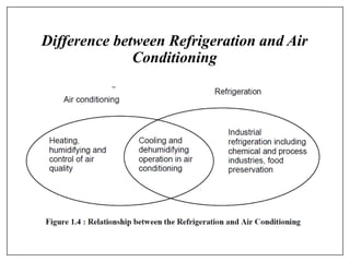
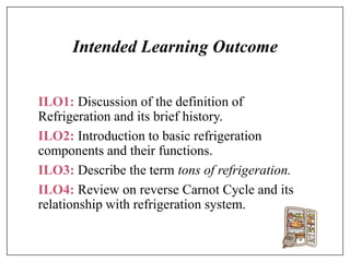
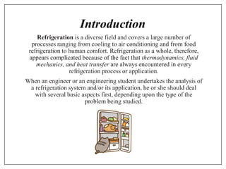
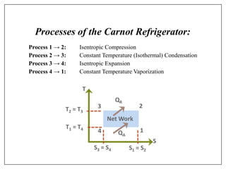
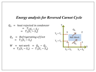
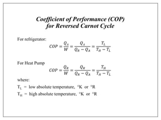
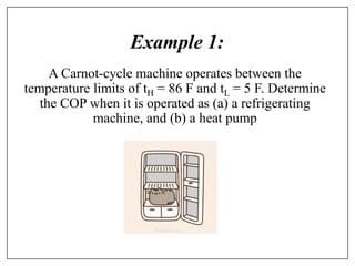
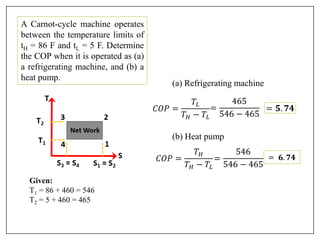
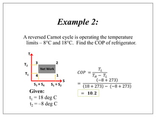
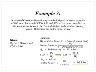
MODULE
1
Introduction to Refrigeration System
Difference between Refrigeration and Air
Conditioning
Intended Learning Outcome
ILO1: Discussion of the definition of
Refrigeration and its brief history.
ILO2: Introduction to basic refrigeration
components and their functions.
ILO3: Describe the term tons of refrigeration.
ILO4: Review on reverse Carnot Cycle and its
relationship with refrigeration system.
Introduction
Refrigeration is a diverse field and covers a large number of
processes ranging from cooling to air conditioning and from food
refrigeration to human comfort. Refrigeration as a whole, therefore,
appears complicated because of the fact that thermodynamics, fluid
mechanics, and heat transfer are always encountered in every
refrigeration process or application.
When an engineer or an engineering student undertakes the analysis of
a refrigeration system and/or its application, he or she should deal
with several basic aspects first, depending upon the type of the
problem being studied.
Definition
Refrigeration is the process of removing heat from an enclosed
space, or from a substance, and rejecting it elsewhere for the primary
purpose of lowering the temperature of the enclosed space or
substance and then maintaining that lower temperature.
As known, two common methods of refrigeration are natural and
mechanical.
In the natural refrigeration, ice has been used in refrigeration since ancient
times and it is still widely used.
In the mechanical refrigeration, the refrigerant is a substance capable of
transferring heat that it absorbs at low temperatures and pressures to a
condensing medium; in the region of transfer, the refrigerant is at higher
temperatures and pressures. By means of expansion, compression, and a
cooling medium, such as air or water, the refrigerant removes heat from a
substance and transfers it to the cooling medium.
Brief History
• In 1755, William Cullen, a Scottish physician, obtained sufficiently low
temperatures for ice making. He accomplished this by reducing the pressure
on water in a closed container with an air pump. At a very low pressure the
liquid evaporated or boiled at a low temperature. The heat required for a
portion of water to change phase from liquid to vapor was taken from the
rest of the water, and at least part of the water remaining turned to ice.
• In 1834, Jacob Perkins, an American residing in England, constructed and
patented a vapor-compression machine with a compressor, a condenser, an
evaporator, and a valve between the condenser and the evaporator (Critchell
and Raymond, 1912).
• In Europe, Dr Alexander C. Kirk commercially developed a closed-cycle
refrigerating machine in 1862, and Franz Windhausen invented a closed-
cycle machine and patented it in America in 1870. The open-cycle
refrigerating machines theoretically outlined by Kelvin and Rankine in the
early 1850s were invented by a Frenchman, Paul Giffard, in 1873 and by
Joseph J. Coleman and James Bell in Britain in 1877 (Roelker, 1906).
• In 1860, a French engineer, Ferdinand P. Edmond Carre, invented an
intermittent crude ammonia absorption apparatus based on the chemical
affinity of ammonia for water, which produced ice on a limited scale.
• One of the earliest of the vapor-compression machines was invented and
patented by an American professor, Alexander C. Twining, in 1853. He
established an ice production plant using this system in Cleveland, Ohio,
and could produce close to a ton per day.
• Carl von Linde, a German scientist, invented a portable compressor
refrigeration machine using methyl ether in 1873, and in 1876 switched
to ammonia. In 1894, Linde also developed new methods for liquefying
large amounts of air.
• Albert T. Marshall, an American inventor, patented the first mechanical
refrigerator in 1899.
• Renowned physicist Albert Einstein patented a refrigerator in 1930 with
the idea of creating an environmentally friendly refrigerator with no
moving parts and did not rely on electricity.
Main Refrigeration Systems
A thermodynamic system acting as a
refrigerator.
The absolute temperature of the source
is TL and the heat transferred from the
source is the refrigeration effect
(refrigeration load) QL. On the other
side, the heat rejection to the sink at the
temperature TH is QH. Both effects are
accomplished by the work input W. For
continuous operation, the first law of
thermodynamics is applied to the system.
Mechanical Refrigeration and
their basic components
A basic vapor-compression refrigeration
system
Refrigerated
Space
Compressor
Motor
Condenser
Expansion
Valve
Evaporator
Coils
Mechanical Refrigeration
Refrigeration System Components
Major components of a vapor-
compression refrigeration system
are as follows:
• compressor,
• condenser,
• evaporator, and
• throttling device.
Basic Components
1. Compressor
❖compresses refrigerant vapor and
causes it to flow in the system.
❖which increases the pressure of
the refrigerant vapor, pushing it
through the system, and increasing
the vapor's temperature above that
of the surrounding.
2. Condenser
❖the refrigerant condenses
while rejecting heat to the
cooling medium which is
either air or water.
❖usually behind the
refrigerator, where the
refrigerant vapor
condenses to a liquid.
3. Expansion Valve
❖ reduces the pressure of the
refrigerant so that low
temperature will be attained;
regulates the flow of the
refrigerant to the evaporator.
❖ which causes a sudden drop
in refrigerant pressure, causing
it to boil; also called a
"metering" valve, since it
passes only as much liquid as
can be completely vaporized in
the evaporator.
4. Evaporator
❖the liquid portion of the
refrigerant evaporates while
absorbing heat from the
surrounding.
❖where the latent heat of
refrigerant vaporization is
absorbed from the cold box.
Unit of Refrigeration and COP
The standard unit of refrigeration is ton of refrigeration or
simply ton denoted by TOR. It is equivalent to the rate of
heat transfer needed to produce 1 ton (2000 lbs) of ice at
32F from water at 32F in one day, i.e., 24 hours. The
enthalpy of solidification of water from and at 32F in
British thermal unit is 144 Btu/lb.
1 𝑇𝑂𝑅 =
2000𝑙𝑏 × 144𝐵𝑇𝑈/𝑙𝑏
24 ℎ𝑟
= 12000
𝐵𝑇𝑈
ℎ𝑟
=
200𝐵𝑇𝑈
𝑚𝑖𝑛
In general, 1 TOR means 200 Btu of heat removal
per minute. Thus, if a refrigeration system is
capable of cooling at the rate of 400 Btu/min, it is
a 2-ton machine. A machine of 20-ton rating is
capable of cooling at a rate of 20  200 = 4000
Btu/min. This unit of refrigeration is currently in
use in the USA, the UK and India.
In many countries, the standard MKS unit of
kcal/hr is used. Other conversions are:
1 ton of refrigeration = 50 kcal/min
= 3.516 kJ/sec
Refrigeration effect is an important term in refrigeration that defines
the amount of cooling produced by a system. This cooling is obtained
at the expense of some form of energy. Therefore, it is customary to
define a term called coefficient of performance (COP) as the ratio of
the refrigeration effect to energy input.
𝐶𝑂𝑃 =
𝑅𝑒𝑓𝑟𝑖𝑔𝑒𝑟𝑎𝑡𝑖𝑜𝑛 𝑒𝑓𝑓𝑒𝑐𝑡
𝐸𝑛𝑒𝑟𝑔𝑦 𝑖𝑛𝑝𝑢𝑡
While calculating COP, both refrigeration effect and energy input
should be in the same unit.
Energy Efficiency Ratio (EER)
Energy Efficiency Ratio (EER) is the ratio of the energy removed at
the evaporator (refrigerating effect) to the electrical energy consumed.
𝐸𝐸𝑅 =
𝑅𝑒𝑓𝑟𝑖𝑔𝑒𝑟𝑎𝑡𝑖𝑜𝑛 𝑒𝑓𝑓𝑒𝑐𝑡
𝐸𝑙𝑒𝑐𝑡𝑟𝑖𝑐𝑡𝑦 𝐶𝑜𝑛𝑠𝑢𝑚𝑝𝑡𝑖𝑜𝑛 (𝑘𝑊)
Reversed Carnot Cycle
Reversed Carnot Cycle is also called Carnot Refrigerator and it has the
highest coefficient of performance (COP) compared to other
refrigeration cycles for the same temperature limits.
Refrigerator
a device having a primary objective is to cool the lower temperature
space.
Heat Pump
a device in which the objective is to heat the higher-temperature
space.
Schematic Diagram of Reversed Carnot Cycle
1
2
3
4
QR
QA
WC
Comp
Expander Net Work
T2 = T3
T1 = T4
T
S
S1 = S2
S3 = S4
1
2
3
4
QR
QA
Processes of the Carnot Refrigerator:
Process 1 → 2: Isentropic Compression
Process 2 → 3: Constant Temperature (Isothermal) Condensation
Process 3 → 4: Isentropic Expansion
Process 4 → 1: Constant Temperature Vaporization
Net Work
T2 = T3
T1 = T4
T
S
S1 = S2
S3 = S4
1
2
3
4
QR
QA
Energy analysis for Reversed Carnot Cycle
𝑄𝑅 = ℎ𝑒𝑎𝑡 𝑟𝑒𝑗𝑒𝑐𝑡𝑒𝑑 𝑖𝑛 𝑐𝑜𝑛𝑑𝑒𝑛𝑠𝑒𝑟
= 𝑇2 𝑆2 − 𝑆3
= 𝑇2(𝑆1 − 𝑆4)
𝑄𝐴 = 𝑅𝑒𝑓𝑟𝑖𝑔𝑒𝑟𝑎𝑡𝑖𝑛𝑔 𝑒𝑓𝑓𝑒𝑐𝑡
= 𝑇1(𝑆1 − 𝑆4)
𝑊 = 𝑛𝑒𝑡 𝑤𝑜𝑟𝑘 = 𝑄𝑅 − 𝑄𝐴
= 𝑇2(𝑆1 − 𝑆4) − 𝑇1(𝑆1 − 𝑆4)
Net Work
T2 = T3
T1 = T4
T
S
S1 = S2
S3 = S4
1
2
3
4
QR
QA
Coefficient of Performance (COP)
for Reversed Carnot Cycle
For refrigerator:
𝐶𝑂𝑃 =
𝑄𝐴
𝑊
=
𝑄𝐴
𝑄𝑅 − 𝑄𝐴
=
𝑇𝐿
𝑇𝐻 − 𝑇𝐿
For Heat Pump
𝐶𝑂𝑃 =
𝑄𝑅
𝑊
=
𝑄𝑅
𝑄𝑅 − 𝑄𝐴
=
𝑇𝐻
𝑇𝐻 − 𝑇𝐿
where:
TL = low absolute temperature, K or R
TH = high absolute temperature, K or R
A Carnot-cycle machine operates between the
temperature limits of tH = 86 F and tL = 5 F. Determine
the COP when it is operated as (a) a refrigerating
machine, and (b) a heat pump
Example 1:
Given:
T1 = 86 + 460 = 546
T2 = 5 + 460 = 465
A Carnot-cycle machine operates
between the temperature limits of
tH = 86 F and tL = 5 F. Determine
the COP when it is operated as (a)
a refrigerating machine, and (b) a
heat pump.
(a) Refrigerating machine
𝐶𝑂𝑃 =
𝑇𝐿
𝑇𝐻 − 𝑇𝐿
=
465
546 − 465
= 𝟓. 𝟕𝟒
(b) Heat pump
𝐶𝑂𝑃 =
𝑇𝐻
𝑇𝐻 − 𝑇𝐿
=
546
546 − 465
= 𝟔. 𝟕𝟒
A reversed Carnot cycle is operating the temperature
limits – 8C and 18C. Find the COP of refrigerator.
Example 2:
Given:
t1 = 18 deg C
t2 = –8 deg C
𝐶𝑂𝑃 =
𝑇𝐿
𝑇𝐻 − 𝑇𝐿
=
−8 + 273
)
18 + 273 − (−8 + 273
= 𝟏𝟎. 𝟐
Example 3:
A reversed Carnot refrigeration system is designed to have a capacity
of 100 tons. Its actual COP is 5.86 and 35% of the power supplied to
the compressor is lost in the form of friction and cylinder cooling
losses. Determine the motor power in kw.
Given:
𝑄𝐴 = 100 𝑡𝑜𝑛𝑠 𝑟𝑒𝑓
𝐶𝑂𝑃 = 5.86
Solution:
𝑄𝐴 = 100 𝑡𝑜𝑛𝑠 𝑟𝑒𝑓 = 351.6 𝑘𝑤
𝐶𝑂𝑃 =
𝑄𝐴
𝑊
𝑐
5.86 =
351.6
𝑊
𝑐
𝑊𝑐 = 60 𝑘𝑤
𝑀𝑜𝑡𝑜𝑟 𝑃𝑜𝑤𝑒𝑟 =
60
1 − 0.35
𝑊𝐶 = 𝑀𝑜𝑡𝑜𝑟 𝑃𝑜𝑤𝑒𝑟 (1 − 𝑃𝑒𝑟𝑐𝑒𝑛𝑡 𝑝𝑜𝑤𝑒𝑟 𝑙𝑜𝑠𝑠)
𝑀𝑜𝑡𝑜𝑟 𝑃𝑜𝑤𝑒𝑟 =
𝑊𝐶
1 − 𝑃𝑒𝑟𝑐𝑒𝑛𝑡 𝑝𝑜𝑤𝑒𝑟 𝑙𝑜𝑠𝑠
= 92.3 𝑘𝑤
Exercise 1
Conduct research activities by visiting the e-library resources of our
university if necessary. Next meeting, we will discuss them carefully.
The instructor will call any of the students to discuss the following:
1. What is refrigerant?
2. How are refrigerants classified?
3. What are the desirable properties of a good refrigerant?
4. What is a Pressure-Enthalpy diagram for a refrigerant? Give an
example.

[1] Introduction to Refrigeration Systems_removed.pdf

  • 1.
  • 2.
  • 3.
    Intended Learning Outcome ILO1:Discussion of the definition of Refrigeration and its brief history. ILO2: Introduction to basic refrigeration components and their functions. ILO3: Describe the term tons of refrigeration. ILO4: Review on reverse Carnot Cycle and its relationship with refrigeration system.
  • 4.
    Introduction Refrigeration is adiverse field and covers a large number of processes ranging from cooling to air conditioning and from food refrigeration to human comfort. Refrigeration as a whole, therefore, appears complicated because of the fact that thermodynamics, fluid mechanics, and heat transfer are always encountered in every refrigeration process or application. When an engineer or an engineering student undertakes the analysis of a refrigeration system and/or its application, he or she should deal with several basic aspects first, depending upon the type of the problem being studied.
  • 5.
    Definition Refrigeration is theprocess of removing heat from an enclosed space, or from a substance, and rejecting it elsewhere for the primary purpose of lowering the temperature of the enclosed space or substance and then maintaining that lower temperature. As known, two common methods of refrigeration are natural and mechanical. In the natural refrigeration, ice has been used in refrigeration since ancient times and it is still widely used. In the mechanical refrigeration, the refrigerant is a substance capable of transferring heat that it absorbs at low temperatures and pressures to a condensing medium; in the region of transfer, the refrigerant is at higher temperatures and pressures. By means of expansion, compression, and a cooling medium, such as air or water, the refrigerant removes heat from a substance and transfers it to the cooling medium.
  • 6.
    Brief History • In1755, William Cullen, a Scottish physician, obtained sufficiently low temperatures for ice making. He accomplished this by reducing the pressure on water in a closed container with an air pump. At a very low pressure the liquid evaporated or boiled at a low temperature. The heat required for a portion of water to change phase from liquid to vapor was taken from the rest of the water, and at least part of the water remaining turned to ice. • In 1834, Jacob Perkins, an American residing in England, constructed and patented a vapor-compression machine with a compressor, a condenser, an evaporator, and a valve between the condenser and the evaporator (Critchell and Raymond, 1912). • In Europe, Dr Alexander C. Kirk commercially developed a closed-cycle refrigerating machine in 1862, and Franz Windhausen invented a closed- cycle machine and patented it in America in 1870. The open-cycle refrigerating machines theoretically outlined by Kelvin and Rankine in the early 1850s were invented by a Frenchman, Paul Giffard, in 1873 and by Joseph J. Coleman and James Bell in Britain in 1877 (Roelker, 1906).
  • 7.
    • In 1860,a French engineer, Ferdinand P. Edmond Carre, invented an intermittent crude ammonia absorption apparatus based on the chemical affinity of ammonia for water, which produced ice on a limited scale. • One of the earliest of the vapor-compression machines was invented and patented by an American professor, Alexander C. Twining, in 1853. He established an ice production plant using this system in Cleveland, Ohio, and could produce close to a ton per day. • Carl von Linde, a German scientist, invented a portable compressor refrigeration machine using methyl ether in 1873, and in 1876 switched to ammonia. In 1894, Linde also developed new methods for liquefying large amounts of air. • Albert T. Marshall, an American inventor, patented the first mechanical refrigerator in 1899. • Renowned physicist Albert Einstein patented a refrigerator in 1930 with the idea of creating an environmentally friendly refrigerator with no moving parts and did not rely on electricity.
  • 8.
    Main Refrigeration Systems Athermodynamic system acting as a refrigerator. The absolute temperature of the source is TL and the heat transferred from the source is the refrigeration effect (refrigeration load) QL. On the other side, the heat rejection to the sink at the temperature TH is QH. Both effects are accomplished by the work input W. For continuous operation, the first law of thermodynamics is applied to the system.
  • 9.
    Mechanical Refrigeration and theirbasic components A basic vapor-compression refrigeration system
  • 10.
  • 11.
    Refrigeration System Components Majorcomponents of a vapor- compression refrigeration system are as follows: • compressor, • condenser, • evaporator, and • throttling device.
  • 12.
    Basic Components 1. Compressor ❖compressesrefrigerant vapor and causes it to flow in the system. ❖which increases the pressure of the refrigerant vapor, pushing it through the system, and increasing the vapor's temperature above that of the surrounding.
  • 13.
    2. Condenser ❖the refrigerantcondenses while rejecting heat to the cooling medium which is either air or water. ❖usually behind the refrigerator, where the refrigerant vapor condenses to a liquid.
  • 14.
    3. Expansion Valve ❖reduces the pressure of the refrigerant so that low temperature will be attained; regulates the flow of the refrigerant to the evaporator. ❖ which causes a sudden drop in refrigerant pressure, causing it to boil; also called a "metering" valve, since it passes only as much liquid as can be completely vaporized in the evaporator.
  • 15.
    4. Evaporator ❖the liquidportion of the refrigerant evaporates while absorbing heat from the surrounding. ❖where the latent heat of refrigerant vaporization is absorbed from the cold box.
  • 16.
    Unit of Refrigerationand COP The standard unit of refrigeration is ton of refrigeration or simply ton denoted by TOR. It is equivalent to the rate of heat transfer needed to produce 1 ton (2000 lbs) of ice at 32F from water at 32F in one day, i.e., 24 hours. The enthalpy of solidification of water from and at 32F in British thermal unit is 144 Btu/lb. 1 𝑇𝑂𝑅 = 2000𝑙𝑏 × 144𝐵𝑇𝑈/𝑙𝑏 24 ℎ𝑟 = 12000 𝐵𝑇𝑈 ℎ𝑟 = 200𝐵𝑇𝑈 𝑚𝑖𝑛
  • 17.
    In general, 1TOR means 200 Btu of heat removal per minute. Thus, if a refrigeration system is capable of cooling at the rate of 400 Btu/min, it is a 2-ton machine. A machine of 20-ton rating is capable of cooling at a rate of 20  200 = 4000 Btu/min. This unit of refrigeration is currently in use in the USA, the UK and India. In many countries, the standard MKS unit of kcal/hr is used. Other conversions are: 1 ton of refrigeration = 50 kcal/min = 3.516 kJ/sec
  • 18.
    Refrigeration effect isan important term in refrigeration that defines the amount of cooling produced by a system. This cooling is obtained at the expense of some form of energy. Therefore, it is customary to define a term called coefficient of performance (COP) as the ratio of the refrigeration effect to energy input. 𝐶𝑂𝑃 = 𝑅𝑒𝑓𝑟𝑖𝑔𝑒𝑟𝑎𝑡𝑖𝑜𝑛 𝑒𝑓𝑓𝑒𝑐𝑡 𝐸𝑛𝑒𝑟𝑔𝑦 𝑖𝑛𝑝𝑢𝑡 While calculating COP, both refrigeration effect and energy input should be in the same unit.
  • 19.
    Energy Efficiency Ratio(EER) Energy Efficiency Ratio (EER) is the ratio of the energy removed at the evaporator (refrigerating effect) to the electrical energy consumed. 𝐸𝐸𝑅 = 𝑅𝑒𝑓𝑟𝑖𝑔𝑒𝑟𝑎𝑡𝑖𝑜𝑛 𝑒𝑓𝑓𝑒𝑐𝑡 𝐸𝑙𝑒𝑐𝑡𝑟𝑖𝑐𝑡𝑦 𝐶𝑜𝑛𝑠𝑢𝑚𝑝𝑡𝑖𝑜𝑛 (𝑘𝑊)
  • 20.
    Reversed Carnot Cycle ReversedCarnot Cycle is also called Carnot Refrigerator and it has the highest coefficient of performance (COP) compared to other refrigeration cycles for the same temperature limits. Refrigerator a device having a primary objective is to cool the lower temperature space. Heat Pump a device in which the objective is to heat the higher-temperature space.
  • 21.
    Schematic Diagram ofReversed Carnot Cycle 1 2 3 4 QR QA WC Comp Expander Net Work T2 = T3 T1 = T4 T S S1 = S2 S3 = S4 1 2 3 4 QR QA
  • 22.
    Processes of theCarnot Refrigerator: Process 1 → 2: Isentropic Compression Process 2 → 3: Constant Temperature (Isothermal) Condensation Process 3 → 4: Isentropic Expansion Process 4 → 1: Constant Temperature Vaporization Net Work T2 = T3 T1 = T4 T S S1 = S2 S3 = S4 1 2 3 4 QR QA
  • 23.
    Energy analysis forReversed Carnot Cycle 𝑄𝑅 = ℎ𝑒𝑎𝑡 𝑟𝑒𝑗𝑒𝑐𝑡𝑒𝑑 𝑖𝑛 𝑐𝑜𝑛𝑑𝑒𝑛𝑠𝑒𝑟 = 𝑇2 𝑆2 − 𝑆3 = 𝑇2(𝑆1 − 𝑆4) 𝑄𝐴 = 𝑅𝑒𝑓𝑟𝑖𝑔𝑒𝑟𝑎𝑡𝑖𝑛𝑔 𝑒𝑓𝑓𝑒𝑐𝑡 = 𝑇1(𝑆1 − 𝑆4) 𝑊 = 𝑛𝑒𝑡 𝑤𝑜𝑟𝑘 = 𝑄𝑅 − 𝑄𝐴 = 𝑇2(𝑆1 − 𝑆4) − 𝑇1(𝑆1 − 𝑆4) Net Work T2 = T3 T1 = T4 T S S1 = S2 S3 = S4 1 2 3 4 QR QA
  • 24.
    Coefficient of Performance(COP) for Reversed Carnot Cycle For refrigerator: 𝐶𝑂𝑃 = 𝑄𝐴 𝑊 = 𝑄𝐴 𝑄𝑅 − 𝑄𝐴 = 𝑇𝐿 𝑇𝐻 − 𝑇𝐿 For Heat Pump 𝐶𝑂𝑃 = 𝑄𝑅 𝑊 = 𝑄𝑅 𝑄𝑅 − 𝑄𝐴 = 𝑇𝐻 𝑇𝐻 − 𝑇𝐿 where: TL = low absolute temperature, K or R TH = high absolute temperature, K or R
  • 25.
    A Carnot-cycle machineoperates between the temperature limits of tH = 86 F and tL = 5 F. Determine the COP when it is operated as (a) a refrigerating machine, and (b) a heat pump Example 1:
  • 26.
    Given: T1 = 86+ 460 = 546 T2 = 5 + 460 = 465 A Carnot-cycle machine operates between the temperature limits of tH = 86 F and tL = 5 F. Determine the COP when it is operated as (a) a refrigerating machine, and (b) a heat pump. (a) Refrigerating machine 𝐶𝑂𝑃 = 𝑇𝐿 𝑇𝐻 − 𝑇𝐿 = 465 546 − 465 = 𝟓. 𝟕𝟒 (b) Heat pump 𝐶𝑂𝑃 = 𝑇𝐻 𝑇𝐻 − 𝑇𝐿 = 546 546 − 465 = 𝟔. 𝟕𝟒
  • 27.
    A reversed Carnotcycle is operating the temperature limits – 8C and 18C. Find the COP of refrigerator. Example 2: Given: t1 = 18 deg C t2 = –8 deg C 𝐶𝑂𝑃 = 𝑇𝐿 𝑇𝐻 − 𝑇𝐿 = −8 + 273 ) 18 + 273 − (−8 + 273 = 𝟏𝟎. 𝟐
  • 28.
    Example 3: A reversedCarnot refrigeration system is designed to have a capacity of 100 tons. Its actual COP is 5.86 and 35% of the power supplied to the compressor is lost in the form of friction and cylinder cooling losses. Determine the motor power in kw. Given: 𝑄𝐴 = 100 𝑡𝑜𝑛𝑠 𝑟𝑒𝑓 𝐶𝑂𝑃 = 5.86 Solution: 𝑄𝐴 = 100 𝑡𝑜𝑛𝑠 𝑟𝑒𝑓 = 351.6 𝑘𝑤 𝐶𝑂𝑃 = 𝑄𝐴 𝑊 𝑐 5.86 = 351.6 𝑊 𝑐 𝑊𝑐 = 60 𝑘𝑤 𝑀𝑜𝑡𝑜𝑟 𝑃𝑜𝑤𝑒𝑟 = 60 1 − 0.35 𝑊𝐶 = 𝑀𝑜𝑡𝑜𝑟 𝑃𝑜𝑤𝑒𝑟 (1 − 𝑃𝑒𝑟𝑐𝑒𝑛𝑡 𝑝𝑜𝑤𝑒𝑟 𝑙𝑜𝑠𝑠) 𝑀𝑜𝑡𝑜𝑟 𝑃𝑜𝑤𝑒𝑟 = 𝑊𝐶 1 − 𝑃𝑒𝑟𝑐𝑒𝑛𝑡 𝑝𝑜𝑤𝑒𝑟 𝑙𝑜𝑠𝑠 = 92.3 𝑘𝑤
  • 29.
    Exercise 1 Conduct researchactivities by visiting the e-library resources of our university if necessary. Next meeting, we will discuss them carefully. The instructor will call any of the students to discuss the following: 1. What is refrigerant? 2. How are refrigerants classified? 3. What are the desirable properties of a good refrigerant? 4. What is a Pressure-Enthalpy diagram for a refrigerant? Give an example.