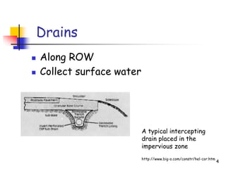
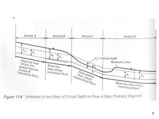
1
Design of Open Channels and
Culverts
2
Transverse Slopes
 Removes water from pavement
surfaces in shortest amount of time
possible
3
Longitudinal Slopes
 Gradient
longitudinal
direction of
highway to
facilitate
movement of
water along
roadway
4
Drains
 Along ROW
 Collect surface water
A typical intercepting
drain placed in the
impervious zone
http://www.big-o.com/constr/hel-cor.htm
5
Drainage Channels (Ditches)
 Design
 Adequate capacity
 Minimum hazard to traffic
 Hydraulic efficiency
 Ease of maintenance
 Desirable design (for safety): flat
slopes, broad bottom, and liberal
rounding
6
Ditch Shape
 Trapezoidal – generally preferred
considering hydraulics, maintenance,
and safety
 V-shaped – less desirable from
safety point of view and
maintenance
7
8
Flow Velocity
• Depends on lining type
• Typically 1 to 5% slopes used
• Should be high enough to prevent deposit
of transported material (sedimentation)
• For most linings, problem if S < 1%
• Should be low enough to prevent erosion
(scour)
• For most types of linings, problem if S > 5%
9
Use spillway or chute if Δelev is large
10
Rip Rap for drainage over high slope
11
Side Ditch/Open Channel Design-Basics
• Find expected Q at point of interest
(see previous lecture)
• Select a cross section for the slope,
and any erosion control needed
• Manning’s formula used for design
• Assume steady flow in a uniform
channel
12
Manning’s Formula
V = R2/3*S1/2 (metric) V = 1.486 R2/3*S1/2
n n
where:
V = mean velocity (m/sec or ft/sec)
R = hydraulic radius (m, ft) = area of the cross section
of flow (m2, ft2) divided by wetted perimeter (m,f)
S = slope of channel
n = Manning’s roughness coefficient
13
Side Ditch/Open Channel
Design-Basics
Q = VA
Q = discharge (ft3/sec, m3/sec)
A = area of flow cross section
(ft2, m2)
FHWA Hydraulic Design Charts
FHWA has developed charts to solve
Manning’s equation for different cross
sections
14
15
Open Channel Example
 Runoff = 340 ft3/sec (Q)
 Slope = 1%
 Manning’s # = 0.015
 Determine necessary cross-section to
handle estimated runoff
 Use rectangular channel 6-feet wide
16
Open Channel Example
Q = 1.486 R2/3*S1/2
n
 Hydraulic radius, R = a/P
 a = area, P = wetted perimeter
P
17
Open Channel Example
 Flow depth = d
 Area = 6 feet x d
 Wetted perimeter = 6 + 2d
6 feet
Flow depth (d)
18
Example (continued)
Q = 1.486 a R2/3*S1/2
n
340 ft3/sec = 1.486 (6d) (6d)2/3 (0.01)1/2
(6 + 2d)
0.015
d  4 feet
Channel area needs to be at least 4’ x 6’
19
Example (continued)
Find flow velocities.
V = 1.486 R2/3*S1/2
n
with R = a/P = 6 ft x 4 ft = 1.714
2(4ft) + 6ft
so, V = 1.486(1.714)2/3 (0.01)1/2 = 14.2 ft/sec
0.015
If you already know Q, simpler just to do
V=Q/A = 340/24 = 14.2)
20
21
Example (continued)
Find critical velocities.
From chart along critical curve, vc  13 ft/sec
Critical slope = 0.007
Find critical depth: yc = (q2/g)1/3
g = 32.2 ft/sec2
q = flow per foot of width
= 340 ft3/sec /6 feet = 56.67ft2/sec
yc = (56.672/32.2)1/3 = 4.64 feet > depth of 4’
22
Check lining for max depth of flow …
23
24
Rounded
25
A cut slope with ditch
26
A fill slope
27
Inlet or drain marker
28
Ditch treatment near a bridge
US 30 – should pier be protected?
29
A fill slope
30
31
32
Median drain
33
Culvert Design - Basics
 Top of culvert not used as pavement
surface (unlike bridge), usually less than 20
foot span
 > 20 feet use a bridge
 Three locations
 Bottom of Depression (no watercourse)
 Natural stream intersection with roadway
(Majority)
 Locations where side ditch surface drainage
must cross roadway
34
Hydrologic and Economic Considerations
 Alignment and grade of culvert (with
respect to roadway) are important
 Similar to open channel
 Design flow rate based on storm with
acceptable return period (frequency)
35
Culvert Design Steps
 Obtain site data and roadway cross
section at culvert crossing location
(with approximation of stream
elevation) – best is natural stream
location, alignment, and slope (may
be expensive though)
 Establish inlet/outlet elevations,
length, and slope of culvert
36
Culvert Design Steps
 Determine allowable headwater depth
(and probable tailwater depth) during
design flood – control on design size –
f(topography and nearby land use)
 Select type and size of culvert
 Examine need for energy dissipaters
37
Headwater Depth
 Constriction due to culvert creates
increase in depth of water just upstream
 Allowable level of headwater upstream
usually controls culvert size and inlet
geometry
 Allowable headwater depth depends on
topography and land use in immediate
vicinity
38
Types of culvert flow
 Type of flow depends on total energy
available between inlet and outlet
 Inlet control
 Flow is controlled by headwater depth and inlet
geometry
 Usually occurs when slope of culvert is steep
and outlet is not submerged
 Supercritical, high v, low d
 Most typical
 Following methods ignore velocity head
39
40
Ans.
Example:
Design ElevHW = 230.5
Stream bed at inlet = 224.0
Drop = 6.5’
Flow = 250cfs
5x5 box
HW/D = 1.41
HW = 1.41x5 = 7.1’
Need 7.1’, have 6.5’
Drop box 0.6’ below stream - OK
41
Types of culvert flow
 Outlet control
 When flow is governed by combination of
headwater depth, entrance geometry, tailwater
elevation, and slope, roughness, and length of
culvert
 Subcritical flow
 Frequently occur on flat slopes
 Concept is to find the required HW depth to
sustain Q flow
 Tail water depth often not known (need a
model), so may not be able to estimate for
outlet control conditions
42
43
Example:
Design ElevHW = 230.5
Flow = 250cfs
5x5 box
Stream elev at inlet = 240
200’ culvert
Outlet invert = 240-0.02x200
= 220.0’
Given tail water depth = 6.5’
Check critical depth = 4.3’
from fig. 17.23 (next page)
Depth to hydraulic grade line =
(dc+D)/2 = 4.7 < 6.5, use 6.5’
Head drop = 3.3’ (from chart)
220.0+6.5+3.3 = 229.8’<230.5
OK
44

07 Open Channels.ppt

  • 1.
    1 Design of OpenChannels and Culverts
  • 2.
    2 Transverse Slopes  Removeswater from pavement surfaces in shortest amount of time possible
  • 3.
    3 Longitudinal Slopes  Gradient longitudinal directionof highway to facilitate movement of water along roadway
  • 4.
    4 Drains  Along ROW Collect surface water A typical intercepting drain placed in the impervious zone http://www.big-o.com/constr/hel-cor.htm
  • 5.
    5 Drainage Channels (Ditches) Design  Adequate capacity  Minimum hazard to traffic  Hydraulic efficiency  Ease of maintenance  Desirable design (for safety): flat slopes, broad bottom, and liberal rounding
  • 6.
    6 Ditch Shape  Trapezoidal– generally preferred considering hydraulics, maintenance, and safety  V-shaped – less desirable from safety point of view and maintenance
  • 7.
  • 8.
    8 Flow Velocity • Dependson lining type • Typically 1 to 5% slopes used • Should be high enough to prevent deposit of transported material (sedimentation) • For most linings, problem if S < 1% • Should be low enough to prevent erosion (scour) • For most types of linings, problem if S > 5%
  • 9.
    9 Use spillway orchute if Δelev is large
  • 10.
    10 Rip Rap fordrainage over high slope
  • 11.
    11 Side Ditch/Open ChannelDesign-Basics • Find expected Q at point of interest (see previous lecture) • Select a cross section for the slope, and any erosion control needed • Manning’s formula used for design • Assume steady flow in a uniform channel
  • 12.
    12 Manning’s Formula V =R2/3*S1/2 (metric) V = 1.486 R2/3*S1/2 n n where: V = mean velocity (m/sec or ft/sec) R = hydraulic radius (m, ft) = area of the cross section of flow (m2, ft2) divided by wetted perimeter (m,f) S = slope of channel n = Manning’s roughness coefficient
  • 13.
    13 Side Ditch/Open Channel Design-Basics Q= VA Q = discharge (ft3/sec, m3/sec) A = area of flow cross section (ft2, m2) FHWA Hydraulic Design Charts FHWA has developed charts to solve Manning’s equation for different cross sections
  • 14.
  • 15.
    15 Open Channel Example Runoff = 340 ft3/sec (Q)  Slope = 1%  Manning’s # = 0.015  Determine necessary cross-section to handle estimated runoff  Use rectangular channel 6-feet wide
  • 16.
    16 Open Channel Example Q= 1.486 R2/3*S1/2 n  Hydraulic radius, R = a/P  a = area, P = wetted perimeter P
  • 17.
    17 Open Channel Example Flow depth = d  Area = 6 feet x d  Wetted perimeter = 6 + 2d 6 feet Flow depth (d)
  • 18.
    18 Example (continued) Q =1.486 a R2/3*S1/2 n 340 ft3/sec = 1.486 (6d) (6d)2/3 (0.01)1/2 (6 + 2d) 0.015 d  4 feet Channel area needs to be at least 4’ x 6’
  • 19.
    19 Example (continued) Find flowvelocities. V = 1.486 R2/3*S1/2 n with R = a/P = 6 ft x 4 ft = 1.714 2(4ft) + 6ft so, V = 1.486(1.714)2/3 (0.01)1/2 = 14.2 ft/sec 0.015 If you already know Q, simpler just to do V=Q/A = 340/24 = 14.2)
  • 20.
  • 21.
    21 Example (continued) Find criticalvelocities. From chart along critical curve, vc  13 ft/sec Critical slope = 0.007 Find critical depth: yc = (q2/g)1/3 g = 32.2 ft/sec2 q = flow per foot of width = 340 ft3/sec /6 feet = 56.67ft2/sec yc = (56.672/32.2)1/3 = 4.64 feet > depth of 4’
  • 22.
    22 Check lining formax depth of flow …
  • 23.
  • 24.
  • 25.
    25 A cut slopewith ditch
  • 26.
  • 27.
  • 28.
    28 Ditch treatment neara bridge US 30 – should pier be protected?
  • 29.
  • 30.
  • 31.
  • 32.
  • 33.
    33 Culvert Design -Basics  Top of culvert not used as pavement surface (unlike bridge), usually less than 20 foot span  > 20 feet use a bridge  Three locations  Bottom of Depression (no watercourse)  Natural stream intersection with roadway (Majority)  Locations where side ditch surface drainage must cross roadway
  • 34.
    34 Hydrologic and EconomicConsiderations  Alignment and grade of culvert (with respect to roadway) are important  Similar to open channel  Design flow rate based on storm with acceptable return period (frequency)
  • 35.
    35 Culvert Design Steps Obtain site data and roadway cross section at culvert crossing location (with approximation of stream elevation) – best is natural stream location, alignment, and slope (may be expensive though)  Establish inlet/outlet elevations, length, and slope of culvert
  • 36.
    36 Culvert Design Steps Determine allowable headwater depth (and probable tailwater depth) during design flood – control on design size – f(topography and nearby land use)  Select type and size of culvert  Examine need for energy dissipaters
  • 37.
    37 Headwater Depth  Constrictiondue to culvert creates increase in depth of water just upstream  Allowable level of headwater upstream usually controls culvert size and inlet geometry  Allowable headwater depth depends on topography and land use in immediate vicinity
  • 38.
    38 Types of culvertflow  Type of flow depends on total energy available between inlet and outlet  Inlet control  Flow is controlled by headwater depth and inlet geometry  Usually occurs when slope of culvert is steep and outlet is not submerged  Supercritical, high v, low d  Most typical  Following methods ignore velocity head
  • 39.
  • 40.
    40 Ans. Example: Design ElevHW =230.5 Stream bed at inlet = 224.0 Drop = 6.5’ Flow = 250cfs 5x5 box HW/D = 1.41 HW = 1.41x5 = 7.1’ Need 7.1’, have 6.5’ Drop box 0.6’ below stream - OK
  • 41.
    41 Types of culvertflow  Outlet control  When flow is governed by combination of headwater depth, entrance geometry, tailwater elevation, and slope, roughness, and length of culvert  Subcritical flow  Frequently occur on flat slopes  Concept is to find the required HW depth to sustain Q flow  Tail water depth often not known (need a model), so may not be able to estimate for outlet control conditions
  • 42.
  • 43.
    43 Example: Design ElevHW =230.5 Flow = 250cfs 5x5 box Stream elev at inlet = 240 200’ culvert Outlet invert = 240-0.02x200 = 220.0’ Given tail water depth = 6.5’ Check critical depth = 4.3’ from fig. 17.23 (next page) Depth to hydraulic grade line = (dc+D)/2 = 4.7 < 6.5, use 6.5’ Head drop = 3.3’ (from chart) 220.0+6.5+3.3 = 229.8’<230.5 OK
  • 44.