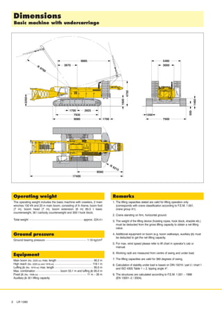
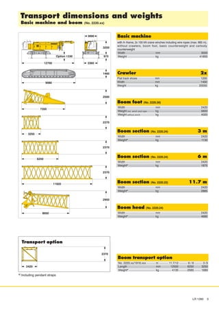
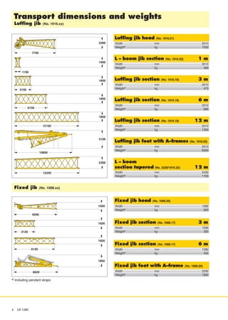
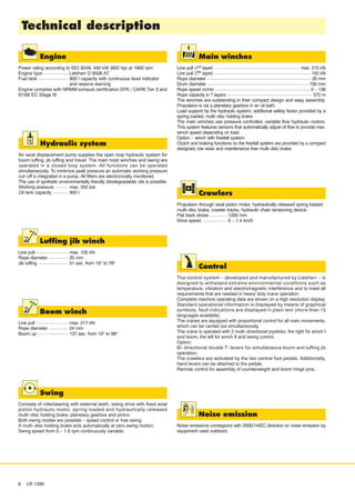
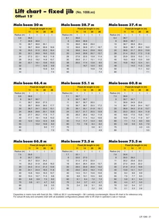
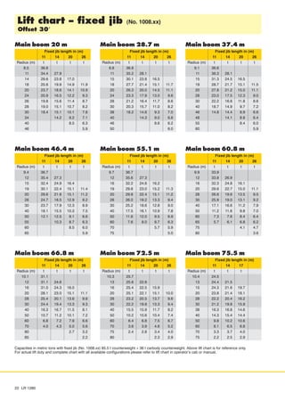
This document provides instructions for assembling a Formula SAE race car frame. It begins with an overview of required skills, safety warnings, and tools. Sections then guide the reader through frame preparation, assembly, and finishing steps. Key steps include using jigs and risers to accurately weld frame members into front, rear, and bottom sections. Upon completion, the frame is heat treated and cleaned before final assembly.
PPT on Theory of Design of Conveyor System for Material HandlingSagar Dhotare
It covers the following points:-
Basics of Belt Conveyor
Types with advantages and disadvantages with application
Requirement of good conveyor
Belt construction
pulley design
Tensioning device
Belt cleaners
PLATAFORMA Y FAMILIA DE PRODUCTOS, GAMA DE PRODUCTOS, SEGMENTACION DEL MERCADO, MODULARIDAD DEL MERCADO, DIAGRAMA DE FUNCION GLOBAL Y DE LAS SUBFUNCIONES, FUNCION COMÚN, RELACION ENTRE MODULARIDAD Y FAMILIA DE PRODUCTOS, SIMILITUD.
The document provides safety training information for crane and hoist operators. It discusses qualifications required, daily inspection requirements, safety rules to follow during operation, and references various industry standards. The key points are:
- Operators must be qualified through training and pass a practical exam on the specific equipment.
- Daily inspections of hooks, wire ropes, brakes and other components are required to check for any defects or damage.
- Safety rules address proper load handling, not exceeding capacity, following signals, and shutting off power when not in use.
- References provided include ASME and OSHA standards on cranes, hoists, slings and other lifting equipment. Proper inspection and following industry
Shanghai Bogvik Wear Material Co., Ltd is one of the most professional crusher parts manufacturer and distributor. We major supply crusher wear parts from 5kgs to 10000kgs in a broad variety of Managnese steel crusher wear parts and alloys steel and chromium iron, Ceramic Insert hammers or blow bars ,Titanium Carbide Insert Liners and crusher spare parts of famous crusher brand .
Wear and spare parts are at the heart of BOGVIK business and we are continually driven to find new and improved ways to optimize component life and equipment performance.
Depending on the application & our clients requirements we offer a range of manganese steel wear parts including Manganese13%, Manganese18% and Manganese22% all with or without chrome & / or molybdenum additions. All manganese liners supplied by BOGVIK are made to our own internal material specifications which are for more stringent than “standard” foundry material specifications.
BOGVIK has in excess of 10000 wear part patterns to fit the world’s most popular crushers. Our patterns cover jaw crushers, cone crushers, gyratory crushers, roll crushers, hammer crushers, horizontal shaft impactors and vertical shaft impactors. No matter what your requirements are, BOGVIK probably already has existing patterns for the wear parts.
We believe in collaboration and work hand-in-hand with our customers to develop solutions that leverages our practical experience, in-house engineering & metallurgical capabilities and manufacturing capacity to provide a complete solution that meets our customer needs.
Contact us today to see how we can help extend service life, improve throughput, optimize supply chain and reduce the total cost of ownership.
sales@bogvik.com
上海勃格维克耐磨材料有限公司是国内最专业的破碎机配件制造商和经销商之一。我们主要供应从 5 公斤到 10000 公斤的各种锰钢破碎机磨损件和合金钢和铬铁、陶瓷插入锤或板锤、碳化钛插入衬板和著名破碎机品牌的破碎机备件。
磨损和备件是勃格维克 业务的核心,我们不断寻求新的和改进的方法来优化部件寿命和设备性能。
根据应用和我们客户的要求,我们提供一系列锰钢耐磨部件,包括锰13%、锰18% 和锰22%,均添加或不添加铬和/或钼。勃格维克 提供的所有锰衬板均按照我们自己的内部材料规格制造,这些规格比“标准”铸造材料规格更严格。
勃格维克 拥有超过 10000 种磨损零件的模具,以适合世界上最受欢迎的破碎机。我们的模具涵盖颚式破碎机、圆锥破碎机、旋回破碎机、辊式破碎机、锤式破碎机、卧式冲击破碎机和立轴式冲击破碎机。无论您需求什么类型的易损件,勃格维克可能已经有此零件的模具。
我们相信与客户携手合作,开发解决方案,利用我们的实践经验、内部工程和冶金能力以及制造能力,提供满足客户需求的完整解决方案。
立即联系我们,了解我们如何帮助延长使用寿命、提高吞吐量、优化供应链并降低总拥有成本。
The document provides guidance on safe lifting practices for engineering students. It discusses duties and responsibilities of riggers which include observing safety precautions, checking the load and work area, inspecting equipment, communicating with crane operators, and reporting issues. The document also covers safety awareness, with sections on general safety, safety systems, personal protective equipment, lifting hazards, electrocution hazards, and overload/maintenance hazards. It describes the importance of using standardized hand signals or radios to properly communicate with crane operators during lifting operations.
This document discusses rigging fundamentals presented by Hennepin Technical College in partnership with OSHA. It covers topics like crane capacity charts, sling inspection requirements, how sling angles affect lifting capacity, the importance of capturing the center of gravity during lifts, and performing test lifts to check load stability. Rigging safety is emphasized to help ensure everyone goes home safely from work each day.
Here are the steps to solve this problem:
1) Use the given linear velocity at A to find the angular velocity of the pulley: ω = v/r = 375 mm/s / 150 mm = 2.5 rad/s
2) Use the given linear acceleration at A to find the angular acceleration of the pulley: α = a/r = 225 mm/s2 / 150 mm = 1.5 rad/s2
3) Use the angular velocity to find the normal acceleration at B: an = rω2 = 150 mm × (2.5 rad/s)2 = 1125 mm/s2
4) The tangential acceleration at B is the same as the given linear acceleration at
This document provides guidance on overhead crane safety. It discusses regulations, crane service classifications based on load and frequency, typical crane components like the hoist, trolley, bridge and their braking systems. It also covers inspections, load detection, and checking mechanical components for wear. Regular inspections are important to identify issues and protect the crane investment and worker safety.
This lifting plan details the procedures and equipment for removing three inlet ducts (DT#01, DT#02, DT#03) from a power plant using two cranes. A 150-ton crawler crane will lift each duct while being repositioned and swung by the crane operator. A trailing 70-ton crane will assist in lowering the ducts onto a trailer. Rigging diagrams and specifications are provided for the cranes and accessories like spreader beams, wire slings, and chain blocks. Each duct will be lifted to a certain height, moved sideways and backed out of place before being lowered onto the trailer.
This handbook provides guidance on worker safety for riggers and signalmen. It outlines proper attire and safety equipment, roles and responsibilities, good and bad rigging practices, inspection of lifting equipment, crane hand signals, and communication best practices. The handbook was produced by the National Crane Safety Taskforce and Workplace Safety and Health Council to educate riggers and signalmen on safe lifting operations.
Manual cutting and bending of rebar poses high safety risks to workers from injuries. Improper cutting and bending of rebar can also compromise the safety of the overall construction and workers. To address these risks, some countries have banned manual rebar work. New automated cutting and bending technologies like Tiscon Readybuild can customize rebar sizes and shapes needed for construction safely and accurately according to project blueprints.
1) The document discusses shear and moment diagrams which graphically show the internal shear and moment forces acting on structural members.
2) It also discusses types of beams including simply supported, continuous, and cantilever beams.
3) Examples are provided for constructing shear and moment diagrams by taking the sum of moments and forces equal to zero and drawing the resulting diagrams based on the boundary conditions.
The document asserts copyright over material written by R.C. Hibbeler and published by Pearson Prentice Hall and Pearson Education. No portion of the copyrighted material may be reproduced without permission in writing from the publisher.
The document discusses lifting operations and safety. It covers common accidents from lifting, legislative requirements, important factors like people, machinery, loads, methods and environment. It then goes into more detail on cranes, lifting gears, and proper inspection and use of wire rope slings, chain slings, shackles and other lifting equipment. Maintaining safe working loads and regularly inspecting all equipment is emphasized to prevent accidents during lifting operations.
This document discusses various types of hoisting equipment and their components. It describes hoisting machines, cranes, and elevators as the main groups of hoisting equipment. It also outlines flexible hoisting appliances like ropes, chains, and wire ropes used to lift loads. Additionally, it explains load handling attachments such as hooks, electric magnets, and grabs. Components like sheaves, sprockets, and drums that work with these flexible appliances are defined. Finally, the document briefly introduces arresting gear used to hold lifted loads.
This document provides a technical description of rail mounted gantry cranes (RMG). It outlines the typical specifications of RMG models including span length, lifting height, travel width, and safe working load. It describes the advantages of RMG for container yards, including increased capacity and efficiency. The document discusses the cranes' motors, speed control system, anti-sway technology, and optional automation features. It also summarizes the diagnostic and management system, which monitors the crane's status, drives, faults, loads, and maintenance needs.
The document outlines the process for designing vertical vessel foundations, including determining the vessel type, design considerations, calculation criteria, and steps. The key steps are: (1) sketching the vessel and foundation, (2) determining equipment and load data, (3) calculating gravity, wind, and seismic loads, (4) checking soil bearing capacity, sliding, and overturning, (5) structurally designing the pedestal with vertical bars, horizontal ties, and top face bars, and (6) calculating anchor forces. The purpose is to ensure the foundation can safely support the vertical vessel according to Saudi Aramco standards.
The document provides an overview of key considerations for rigging jobs, including the load's weight, center of gravity, attachment points, required rigging hardware, lift equipment, and personnel. It discusses determining a load's center of gravity and how rigging to the center of gravity helps control the load. Various factors that affect sling capacities are covered, such as end attachments, splicing efficiency, hitch types, D/d ratios, number of legs used, and load angles. Methods for calculating load sharing and tensions in multi-leg rigging configurations are also presented.
This document provides an overview of the structural design process for steel bins and silos used to store bulk solids. It discusses the following key points in 3 sentences:
1) Bulk solids storage plays an important role in many industries and is generally provided by large steel or concrete bins and silos. 2) The document outlines the full design process, from assessing material properties and flow characteristics to determining design loads and carrying out the structural design. 3) The scope of the text is to provide guidelines for designing typical small to fairly large steel bins, bunkers, hoppers and silos based on conventional shapes and materials with known properties.
The document discusses dynamic force analysis of mechanisms. It begins by introducing the concept of dynamic forces that arise due to accelerating masses in machines. It then describes D'Alembert's principle, which states that inertia forces and external forces together produce static equilibrium. The document provides examples of applying dynamic analysis to mechanisms like four-bar linkages and slider-crank mechanisms. It also discusses determining equivalent inertia forces and torques on different components like the piston, connecting rod, and crankshaft. Graphical methods for analyzing inertia forces in reciprocating engines are also presented.
This document provides an overview of important factors related to safe lifting operations, including common accidents, legislative requirements, roles of personnel, machinery considerations, and types of lifting gears. It discusses cranes like mobile cranes and tower cranes and safe operation points. It also covers various lifting gears such as wire rope slings, chain slings, hooks, and their inspection and proper use. The document emphasizes the importance of following safety procedures and using qualified personnel and properly inspected equipment to reduce lifting accidents.
الأسكندريه
لمحة المتبادلة الشركة محمداحمد عمليات كرين فقط فى مجموعة ليس متخصصه، ولكن أولا وقبل كل شيء في مناولة البضائع الثقيلة. . ليس فقط في تأجير واستعمال الرافعات، ولكن أيضا في حل المشاكل المرتبطة بالعمل رافعة
مفاتيح نجاحنا: الجودة، السلامة، الهندسة و الصيانة. جودة تقديم الجوده والخدمة عامل أخر من هو نجاحنا. نحن نحرص على كل شيء: نتحدث إلى الزبائن، في محاولة لفهم المشكلة وتحليلها. نجد أفضل الحلول المصممة خصيصا لهم بحيث يتم إنجاز العمل بطريقة اقتصادية وآمنة. سلامة لتكون قادرة علي العمل بأمان جدا، وكنت بحاجة ليس فقط أفضل المعدات ولكن أيضا الأشخاص الذين تم تدريبهم لتشغيل هذا الجهاز. هذا هو السبب يضع الكثير من الجهد في تدريب هؤلاء الناس. وبهذه الطريقة فقط، يمكننا أن نضمن السلامة. ت \ 01146324168 01222648010 01140886589 فكس \ 034384069
الأسكندريه
لمحة المتبادلة الشركة محمداحمد عمليات كرين فقط فى مجموعة متخصصه، ولكن أولا وقبل كل شيء في مناولة البضائع الثقيلة. . ليس فقط في تأجير واستعمال الرافعات، ولكن أيضا فى حل المشاكل المرتبطة بالعمل رافعة مفاتيح نجاحنا: الجودة، السلامة، الهندسة و الصيانة. جودة تقديم الجوده والخدمة عامل أخر من هو نجاحنا. نحن نحرص على كل شيء: نتحدث إلى الزبائن، في محاولة لفهم المشكلة وتحليلها. نجد أفضل الحلول المصممة خصيصا لهم بحيث يتم إنجاز العمل بطريقة اقتصادية وآمنة. سلامة لتكون قادرة علي العمل بأمان جدا، وكنت بحاجة ليس فقط أفضل المعدات ولكن أيضا الأشخاص الذين تم تدريبهم لتشغيل هذا الجهاز. هذا هو السبب يضع الكثير من الجهد في تدريب هؤلاء الناس. وبهذه الطريقة فقط، يمكننا أن نضمن السلامة.
ت \ 01146324168
01222648010
01140886589 فكس
\ 034384069 -
في شركة محمدأحمد لتأجير المعدات الاوناش
The document discusses the benefits of exercise for mental health. Regular physical activity can help reduce anxiety and depression and improve mood and cognitive function. Exercise causes chemical changes in the brain that may help protect against mental illness and improve symptoms.
The document discusses industrial accident prevention and control. It outlines steps for recognizing, evaluating, and controlling hazards including chemical, physical, biological, and risk engineering hazards. Methods of control include elimination, substitution, isolation, engineering and administrative controls, and personal protective equipment. The document provides contact information for an expert in this area.
الكٌتيب يتحدث عن السقالات وأنواعها ومكوناتها ومراحل تركيبها وكيفية تثبيت وربط السقالات والعوامل المؤثرة فى تثبيت السقالات واخيرا كيفية فحص السقالات
الكتاب اعداد وتصميم مهندس محمد عبد الحليم امام خليفة
The document discusses major causes of crane accidents such as contact with power lines, overturns, falls, and mechanical failures which are often due to instability of loads, lack of communication, lack of training, and inadequate maintenance or inspection. It notes that crane operators and others on site are at risk and outlines important definitions, parts, types of cranes, hazards, safety planning considerations, load capacities, and the importance of inspections and training to reduce accidents.
This document provides specifications for a hydraulic crawler crane model CKE900-1F, including:
- A maximum lifting capacity of 90 metric tons at 3.4 meters for the crane boom and 10.9 metric tons at 18 meters for the fixed jib.
- The crane boom has a maximum length of 61 meters and the maximum fixed jib combination is 51.8 meters plus 18.3 meters.
- Additional details provided include engine specifications, hydraulic system components, dimensions, working ranges, and lifting capacity charts.
Piletec Brochure - Piling Hammer BrochureLewis Ryan
Piletec Brochure with our full range of EMV, FSV, Croppers, Culvert Puller, Vibration Monitors and Augers.
Specifications of all equipment on offer to hire today.
View the UK's largest fleet of piling attachments.
Coiled Tubing Introduction and Basics.pdfsalem123gmaal
Coiled tubing was originally developed during World War 2 for underwater pipelines. It involves running and retrieving a continuous steel tubing string without connections. This allows operations on live wells while continuously pumping fluids. The document discusses the manufacturing and components of coiled tubing systems. It also summarizes various applications of coiled tubing including wellbore cleanout, circulation, tool conveyance, and completions. The key advantages are its mobility, ability to work on live wells without connections, and role in transporting tools in deviated/horizontal wells. Limitations include small diameters and limited reach in long horizontals.
Alat beratku.blogspot.com 8000-1-product-guide-imperialVonita Allena
This document provides specifications and details for the Manitowoc 8000-1 crane. Key information includes:
- The crane has an 80 US ton capacity, 200 ft heavy-lift boom, and can reach a maximum of 180 ft with a 60 ft jib attachment for a total of 240 ft.
- It is powered by a 285 HP engine and has a maximum line speed of 525 fpm and rated line pull of 17,000 lbs.
- Additional specifications cover dimensions, components like the boom, counterweights, engine, and performance data for the winches and load charts.
- Charts and diagrams show the crane's range of motion, dimensions, component weights and specifications
This document summarizes the specifications of a TL-200M truck crane with a Nissan Diesel KC-KW460MN or Mitsubishi KC-KV207M carrier. It includes details about the crane such as its boom length and extension, jib length, lifting capacities at different boom angles and radii, maximum lifting height, and safety devices. It also provides specifications for the carrier such as its engine, transmission, dimensions, weight, and performance.
Grindex produces submersible heavy-duty pumps for demanding industries like construction, mining, and tunnels. Their pump line includes drainage pumps from 1.3 to 140 HP and sludge pumps. The document discusses features like built-in motor protection, wear resistance, and easy serviceability that reduce operational costs. It provides specifications for individual pump models ranging from the Minex to the Mega.
Self erecting tower cranes are particularly well suited for small building sites because they are quick, nimble, and simple to use is provided by compass equipment
Self erecting tower cranes are particularly well suited for small building sites because they are quick, nimble, and simple to use is provided by compass equipment.
Hyster a265 (n30 zdrs) forklift service repair manualfksefkskemm
This document provides specifications for lubrication, oil capacities, lift capacities, and torque for various models of service trucks. It includes:
1) Recommended lubrication types for hydraulic systems, grease, gear oil, and antiseize for standard, cold storage, and arctic applications.
2) Oil capacity specifications for hydraulic systems, battery compartments, and master drive units for different truck models.
3) Lift capacity, lift and lower speeds, and hydraulic system details like pump displacement and pressure for each truck model.
4) Tire size specifications for different truck models.
Hyster a265 (n40 zrs) forklift service repair manualfjjskefkskem
This document provides specifications for lubrication, oil capacities, lift capacities, and torque for various models of service trucks. It includes:
1) Recommended lubrication types for hydraulic systems, grease, gear oil, and antiseize for standard, cold storage, and arctic applications.
2) Oil capacity specifications for hydraulic systems, battery compartments, and master drive units for different truck models.
3) Lift capacity, lift and lower speeds, and hydraulic system details like pump displacement and pressure for each truck model.
4) Tire size specifications for different truck models.
Hyster a265 (n35 zrs) forklift service repair manualfjjsekfksem
This document provides specifications for lubrication, oil capacities, lift capacities, and torque for various models of service trucks. It includes:
1) Recommended lubrication types for hydraulic systems, grease, gear oil, and antiseize for standard, cold storage, and arctic applications.
2) Oil capacity specifications for hydraulic systems, battery compartments, and master drive units for different truck models.
3) Lift capacity, lift and lower speeds, and hydraulic system details like pump displacement and pressure for each truck model.
4) Tire size specifications for different truck models.
CLAAS DOMINATOR 86 (Type 087) Combine Service Repair Manual.pdffjskemdmdm
This document provides specifications for the CLAAS Dominator 106 combine harvester, including technical data, dimensions, weights, settings, capacities, and descriptions of components. Key details include the cutterbar widths ranging from 3.90 to 7.50 meters, overall machine width of 5565 to 9225 mm depending on cutterbar size, 6500 liter grain tank capacity, 151 kW six-cylinder engine, hydrostatic three-gear transmission for forward and reverse travel, and hydraulic brakes and steering. Dimensional drawings show the harvester in operating and transport positions.
CLAAS DOMINATOR 78 (Type 091) Combine Service Repair Manual.pdfjfksmdmmd
This document provides specifications for the CLAAS Dominator 106 combine harvester, including technical data, dimensions, weights, settings, capacities, and descriptions of components. Key details include the cutterbar widths ranging from 3.90 to 7.50 meters, overall machine width of 5565 to 9225 mm depending on cutterbar size, 6500 liter grain tank capacity, 151 kW six-cylinder engine, hydrostatic three-gear transmission for forward and reverse travel, and hydraulic brakes and steering. Dimensional drawings show the harvester in operating and transport positions.
CLAAS DOMINATOR 76 (Type 084) Combine Service Repair Manual.pdff8usejdjkdidj3e
This document provides specifications for the CLAAS Dominator 106 combine harvester including technical data, dimensions, weights, settings, and capacities. It includes information on the cutterbar, threshing equipment, straw walkers, cleaning system, engines, transmission, hydraulics, electrical system, and auxiliary equipment. Dimensions and specifications are provided for operating and transport positions. Settings such as hydraulic oil pressures, reel speeds, and concave clearances are also listed. The document contains detailed technical specifications for the CLAAS Dominator 106 combine harvester model.
CLAAS DOMINATOR 78 (Type 091) Combine Service Repair Manual.pdffjskemdmdm
This document provides specifications for the CLAAS Dominator 106 combine harvester, including technical data, dimensions, weights, settings, capacities, and descriptions of components. Key details include the cutterbar widths ranging from 3.90 to 7.50 meters, overall machine width of 5565 to 9225 mm depending on cutterbar size, 6500 liter grain tank capacity, 151 kW six-cylinder engine, hydrostatic three-gear transmission for forward and reverse travel, and hydraulic brakes and steering. Dimensional drawings show the harvester in operating and transport positions.
CLAAS DOMINATOR 78 (Type 091) Combine Service Repair Manual.pdffyhsejdkkdmmd3e
This document provides specifications for the CLAAS Dominator 106 combine harvester, including technical data, dimensions, weights, settings, capacities, and descriptions of components. Key details include a 638 cubic inch engine producing 205 horsepower, a cutting width ranging from 13 to 25 feet, a grain tank capacity of 184.6 US bushels, a transport width of 171-363 inches depending on configuration, and hydraulic oil, transmission oil, and engine oil capacities.
CLAAS DOMINATOR 86 (Type 087) Combine Service Repair Manual.pdff8useujdkdkm
This document provides specifications for the CLAAS Dominator 106 combine harvester, including technical data, dimensions, weights, settings, capacities, and descriptions of components. Key details include a 638 cubic inch engine producing 205 horsepower, a cutting width ranging from 13 to 25 feet, a grain tank capacity of 184.6 US bushels, a transport width of 171-363 inches depending on configuration, and hydraulic oil, transmission oil, and engine oil capacities.
CLAAS DOMINATOR 78 (Type 091) Combine Service Repair Manual.pdff8useujdkdkm
This document provides specifications for the CLAAS Dominator 106 combine harvester, including technical data, dimensions, weights, settings, capacities, and descriptions of components. Key details include the cutterbar widths ranging from 3.90 to 7.50 meters, overall machine width of 5565 to 9225 mm depending on cutterbar size, 6500 liter grain tank capacity, 151 kW six-cylinder engine, hydrostatic three-gear transmission for forward and reverse travel, and hydraulic brakes and steering. Dimensional drawings show the harvester in operating and transport positions.
CLAAS DOMINATOR 88 (Type 092) Combine Service Repair Manual.pdff8usejdjkdidj3e
This document provides specifications for the CLAAS Dominator 106 combine harvester including technical data, dimensions, weights, settings, and capacities. It includes information on the cutterbar, threshing equipment, straw walkers, cleaning system, engines, transmission, hydraulics, electrical system, and auxiliary equipment. Dimensions and specifications are provided for operating and transport positions. Settings such as hydraulic oil pressures, tire pressures, and wheel bolt torques are also listed. The document contains detailed technical specifications for the CLAAS Dominator 106 combine harvester model.
CLAAS DOMINATOR 78H (Type 079) Combine Service Repair Manual.pdff8useujdkdkm
This document provides specifications for the CLAAS Dominator 106 combine harvester including technical data, dimensions, weights, settings, and capacities. It includes information on the cutterbar, threshing equipment, straw walkers, cleaning system, engines, transmission, hydraulics, electrical system, and auxiliary equipment. Dimensions and specifications are provided for operating and transport positions. Settings such as hydraulic oil pressures, reel speeds, and concave clearances are also listed. The document contains detailed technical information about the components and configurations of the CLAAS Dominator 106 combine.
Similar to جداول أحمال أوناش 01146324168 لشركة محمدأحمد لإيجار أوناش الرافعا من 50طن 600طن (20)
Discover How Long Do Aluminum Gutters Last?SteveRiddle8
Many people wonder how long aluminum gutters last. In this ppt, we will cover the lifetime of aluminum gutters, appropriate maintenance procedures, and the advantages of using this material for gutter installation.
Top 10 Challenges That Every Web Designer Face on A Daily Basis.pptxe-Definers Technology
In today’s fast-moving digital world, building websites is super important for how well a business does online. But, because things keep changing with technology and what people expect, teams who make websites often run into big problems. These problems can slow down their work and stop them from making really good websites. Let us see what the best website designers in Delhi have to say –
https://www.edtech.in/services/website-designing-development-company-delhi.htm
The Significance of Flowers in Our LivesBISOU Flowers
Flowers are highlighted for their ability to improve emotional well-being and mental health. Their presence in living and workspaces can reduce stress, boost mood, and create a calming atmosphere, contributing to overall mental health.
METS Lab SASO Certificate Services in Dubai.pdfsandeepmetsuae
Achieving compliance with the Saudi Standards, Metrology and Quality Organization (SASO) regulations is crucial for businesses aiming to enter the Saudi market. METS Laboratories offers comprehensive SASO certification services designed to help companies meet these stringent standards efficiently. Our expert team provides end-to-end support, from initial product assessments to final certification, ensuring that all regulatory requirements are meticulously met. By leveraging our extensive experience and state-of-the-art testing facilities, businesses can streamline their certification process, avoid costly delays, and gain a competitive edge in the market. Trust METS Laboratories to guide you through every step of achieving SASO compliance seamlessly.
Job Vacancies in Norway 🇳🇴
Warehouse Workers for Clothing
2year WORKPERMIT 👍
Salary: €3900-4300 per month (Paid twice a month).
Requirements:
* Duties include quality control of products, order picking, packing goods, and applying stickers and labels.
* Work schedule: 8-10 hours per day, 5 days a week.
Documents 📄
*Adhar
Pan
Photo
Education documents
Basic English**o
Education documents
Basic English**
Photo
Education documents
Basic English**
Best Web Development Frameworks in 2024growthgrids
Best Web Development Frameworks: In 2024, the landscape of web development frameworks is diverse, with different frameworks excelling in various aspects such as 1. React, 2. Jquery, 3. MySQL, and 4. ASP.NET. With a strategic blend of manual testing and cutting-edge automated tools, we guarantee a flawless user experience. Partner with Growth Grids and elevate your software quality to new heights.
Contact Us :-
Email: [business@growthgrids.com]
Phone: [+91-9773356002]
Website : https://growthgrids.com
The Fraud Examiner’s Report –
What the Certified Fraud Examiner Should Know
Being a Virtual Training Paper presented at the Association of Certified Fraud Examiners (ACFE) Port Harcourt Chapter Anti-Fraud Training on July 29, 2023.
Stay updated on Siddhivinayak Temple events and timings in Houston, TX. Join our spiritual and community gatherings. Visit us now! gaurisiddhivinayak.org
3 Examples of new capital gains taxes in CanadaLakshay Gandhi
Stay informed about capital gains taxes in Canada with our detailed guide featuring three illustrative examples. Learn what capital gains taxes are and how they work, including how much you pay based on federal and provincial rates. Understand the combined tax rates to see your overall tax liability. Examine specific scenarios with capital gains of $500k and $1M, both before and after recent tax changes. These examples highlight the impact of new regulations and help you navigate your tax obligations effectively. Optimize your financial planning with these essential insights!
💼 Dive into the intricacies of capital gains taxes in Canada with this insightful video! Learn through three detailed examples how these taxes work and how recent changes might impact you.
❓ What are capital gains taxes? Understand the basics of capital gains taxes and why they matter for your investments.
💸 How much taxes do I pay? Discover how the amount of tax you owe is calculated based on your capital gains.
📊 Federal tax rates: Explore the federal tax rates applicable to capital gains in Canada.
🏢 Provincial tax rates: Learn about the varying provincial tax rates and how they affect your overall tax bill.
⚖️ Combined tax rates: See how federal and provincial tax rates combine to determine your total tax obligation.
💵 Example 1 – Capital gains $500k: Examine a scenario where $500,000 in capital gains is taxed.
💰 Example 2 – Capital gains of $1M before the changes: Understand how a $1 million capital gain was taxed before recent changes.
🆕 Example 3 – Capital gains of $1M after the changes: Analyze the tax implications for a $1 million capital gain after the latest tax reforms.
🎉 Conclusion: Summarize the key points and takeaways to help you navigate capital gains taxes effectively.
#CapitalGainsTax #Taxation #CanadianTax #InvestmentTax #TaxRates #FinancialPlanning #TaxReform #CapitalGains #TaxExamples 💼💸📊🏢⚖️💵💰🆕
Bridging the Language Gap The Power of Simultaneous Interpretation in RwandaKasuku Translation Ltd
Rwanda is a nation on the rise, fostering international partnerships and economic growth. With this progress comes a growing need for seamless communication across languages. Simultaneous interpretation emerges as a vital tool in this ever-evolving landscape. When seeking the best simultaneous interpretation in Rwanda, Kasuku Translation stands out as a premier choice.
Emmanuel Katto Uganda - A PhilanthropistMarina Costa
Emmanuel Katto is a well-known businessman from Uganda who is improving his town via his charitable work and commercial endeavors. The Emka Foundation is a non-profit organization that focuses on empowering adolescents through education, business, and skill development. He is the founder and CEO of this organization. His philanthropic journey is deeply personal, driven by a calling to make a positive difference in his home country. Check out the slides to more about his social work.
Merchants from high-risk industries face significant challenges due to their industry reputation, chargeback, and refund rates. These industries include sectors like gambling, adult entertainment, and CBD products, which often struggle to secure merchant accounts due to increased risks of chargebacks and fraud.
To overcome these difficulties, it is necessary to improve credit scores, reduce chargeback rates, and provide detailed business information to high-risk merchant account providers to enhance credibility.
Regarding security, implementing robust security measures such as secure payment gateways, two-factor authentication, and fraud detection software that utilizes machine learning systems is crucial.
If you want a spell that is solely about getting your lover back in your arms, this spell has significant energy just to do that for your love life. This spell has the ability to influence your lover to come home no matter what forces are keeping them away. Using my magical native lost love spells, I can bring back your ex-husband or ex-wife to you, if you still love them and want them back.
Even if they have remarried my lost love spells will bring them back and they will love you once again. By requesting this spell; the lost love of your life could be back on their way to you now. This spell does not force love between partners. It works when there is genuine love between the two but for some unforeseen circumstance, you are now apart.
I cast these advanced spells to bring back lost love where I use the supernatural power and forces to reconnect you with one specific person you want back in your existence. Bring back your ex-lover & make them commit to a relationship with you again using bring back lost love spells that will help ex lost lovers forgive each other.
Losing your loved one sometimes can be inevitable but the process of getting your ex love back to you can be extremely very hard. However, that doesn’t mean that you cannot win your ex back any faster. Getting people to understand each other and create the unbreakable bond is the true work of love spells.
Love spells are magically cast with the divine power to make the faded love to re-germinate with the intensive love power to overcome all the challenges.
My effective bring back lost love spells are powerful within 24 hours. Dropping someone you adore is like breaking your heart in two pieces, especially when you are deeply in love with that character. Love is a vital emotion and has power to do the entirety glad and quality, however there comes a time whilst humans are deserted via their loved ones and are deceived, lied, wronged and blamed. Bring back your ex-girlfriend & make them commit to a relationship with you again using bring back lost love spells to make fall back in love with you.
Make your ex-husband to get back with you using bring back lost love spells to make your ex-husband to fall back in love with you & commit to marriage & with you again.
Bring back lost love spells to help ex-lover resolve past difference & forgive each other for past mistakes. Capture his heart & make him yours using love spells.
His powerful lost lover spell works in an effective and fastest way. By using a lover spell by Prof. Balaj, the individuals can bring back lost love. Its essential fascinating powers can bring back lost love, attract new love, or improve an existing relationship. With the right spell and a little faith, individuals can create the lasting and fulfilling relationship everyone has always desired.
Visit https://www.profbalaj.com/love-spells-loves-spells-that-work/ for more info or
Call/WhatsApp +27836633417 NOW FOR GUARANTEED RESULTS
Pruning enhances your garden's visual appeal by keeping plants neat and well-formed. Whether you prefer a formal, structured look or a more natural, free-flowing design, regular pruning helps you achieve and maintain your desired garden style. A well-pruned garden looks cared for and can significantly improve the overall beauty of your outdoor space.
Understanding Love Compatibility or Synastry: Why It MattersAstroForYou
Love compatibility, often referred to as synastry in astrological terms, is the study of how two individuals’ astrological charts interact with each other.
Electrical Testing Lab Services in Dubai.pdfsandeepmetsuae
An electrical testing lab in Dubai plays a crucial role in ensuring the safety and efficiency of electrical systems across various industries. Equipped with state-of-the-art technology and staffed by experienced professionals, these labs conduct comprehensive tests on electrical components, systems, and installations.
eBrand Promotion Full Service Digital Agency Company ProfileChimaOrjiOkpi
eBrandpromotion.com is Nigeria’s leading Web Design/development and Digital marketing agency. We’ve helped 600+ clients in 24 countries achieve growth revenue of over $160+ Million USD in 12 Years. Whether you’re a Startup or the Unicorn in your industry, we can help your business/organization grow online. Thinking of taking your business online with a professionally designed world-class website or mobile application? At eBrand, we don’t just design beautiful mobile responsive websites/apps, we can guarantee that you will get tangible results or we refund your money…
Gujar Industries India Pvt. Ltd is a leading manufacturer of X-ray baggage scanners in India. With a strong focus on innovation and quality, the company has established itself as a trusted provider of security solutions for various industries. Their X-ray baggage scanners are designed to meet the highest standards of safety and efficiency, making them ideal for use in airports, government buildings, and other high-security environments. Gujar Industries India Pvt. Ltd is committed to providing cutting-edge technology and reliable products to ensure the safety and security of their customers.
Best Immigration Consultants in Amritsar- SAGA StudiesSAGA Studies
Want to fulfill your study abroad dream? Searching for the best Immigration Consultants?
SAGA Studies is the best immigration consultants in Amritsar, provides student admissions, study visa, spouse and dependent visas, tourist visas, PTE exam assistance,and many more.
Forex Copy trading is the mode of trading offering great opportunities to the traders lacking time or in-depth market knowledge, yet willing to use currency trading as a form of investment and to increase their initial funds.
2. Dimensions
2 LR 1280
Operating weight
The operating weight includes the basic machine with crawlers, 2 main
winches 150 kN and 20 m main boom, consisting of A–frame, boom foot
(7 m), boom head (7 m), boom extension (6 m) 85.5 t basic
counterweight, 36 t carbody counterweight and 300 t hook block.
Total weight approx. 224.4 t
Ground pressure
Ground bearing pressure 1.18 kg/cm2
Basic machine with undercarriage
Equipment
Main boom (No. 2220.xx) max. length 90.2 m
High reach (No. 2220.xx and 1916.xx) 119.1 m
Luffing jib (No. 1916.xx) max. length 95.0 m
Max. combination boom 55.1 m and luffing jib 95.0 m
Fixed jib (No. 1008.xx) 11 m – 26 m
Auxiliary jib 30 t lifting capacity
Remarks
1. The lifting capacities stated are valid for lifting operation only
(corresponds with crane classification according to F.E.M. 1.001,
crane group A1).
2. Crane standing on firm, horizontal ground.
3. The weight of the lifting device (hoisting ropes, hook block, shackle etc.)
must be deducted from the gross lifting capacity to obtain a net lifting
value.
4. Additional equipment on boom (e.g. boom walkways, auxiliary jib) must
be deducted to get the net lifting capacity.
5. For max. wind speed please refer to lift chart in operator’s cab or
manual.
6. Working radii are measured from centre of swing and under load.
7. The lifting capacities are valid for 360 degrees of swing.
8. Calculation of stability under load is based on DIN 15019 / part 2 / chart 1
and ISO 4305 Table 1 + 2, tipping angle 4º.
9. The structures are calculated according to F.E.M. 1.001 – 1998
(EN 13001–2 / 2004).
ÑÑ
ÑÑ
Ñ
ÑÑ
ÑÑ
Ñ
ÑÑ
ÑÑ
Ñ
Ñ
Ñ ÑÑ
Ñ
ÑÑÑÑÑ ÑÑÑÑÑ ÑÑÑÑÑÑÑÑÑÑ
ÑÑÑÑÑÑÑÑÑÑÑÑÑÑÑÑÑÑÑÑÑÑÑÑÑ
ÑÑÑÑÑÑ
3. LR 1280 3
*) Including pendant straps
with A–frame, 2x 150 kN crane winches including wire ropes (max. 665 m),
without crawlers, boom foot, basic counterweight and carbody
counterweight
Basic machine
Weight kg 41600
Width mm 3000
Flat track shoes mm 1200
Crawler 2x
Weight kg 20550
Width mm 1400
Boom section (No. 2220.24) 3 m
Weight* kg 1130
Width mm 2420
Boom section (No. 2220.24) 6 m
Weight* kg 1875
Width mm 2420
Boom section (No. 2220.22) 11.7 m
Weight* kg 2885
Width mm 2420
Boom head (No. 2220.24)
Weight* kg 4690
Width mm 2420
Transport dimensions and weights
Basic machine and boom (No. 2220.xx)
Boom transport option
Length mm 12500 6250 3250
Weight* kg 4135 2565 1680
Transport option
Ñ
Ñ Ñ No. 2220.xx/1916.xxx m 11.7/12 6 / 6 3 /3
Ñ
ÑÑÑ
Ñ
Ñ
Ñ
Ñ Ñ
Ñ
ÑÑÑÑÑ ÑÑÑÑÑÑ
ÑÑ
Ñ
ÑÑÑÑÑÑÑÑÑÑÑÑÑÑÑÑÑÑÑÑÑÑÑ
ÑÑÑÑÑÑÑÑ ÑÑÑÑ
Ñ
Ñ
Ñ
Ñ
Boom foot (No. 2220.30)
Weight incl. winch and rope kg 5600
Width mm 2420
Weight without winch kg 4000
4. *) Including pendant straps
Transport dimensions and weights
Luffing jib (No. 1916.xx)
Fixed jib head (No. 1008.20)
Weight* kg 920
Width mm 1090
Fixed jib section (No. 1008.17) 3 m
Weight* kg 300
Width mm 1090
Fixed jib section (No. 1008.17) 6 m
Weight* kg 455
Width mm 1090
Fixed jib foot with A-frame (No. 1008.20)
Weight* kg 1950
Width mm 2200
ÑÑ
ÑÑÑÑÑ
Ñ
ÑÑÑ
Fixed jib (No. 1008.xx)
Luffing jib head (No. 1916.21)
Weight* kg 1550
Width mm 2010
Luffing jib section (No. 1916.18) 6 m
Weight* kg 690
Width mm 2010
Luffing jib section (No. 1916.18) 12 m
Weight* kg 1250
Width mm 2010
Luffing jib foot with A-frames (No. 1916.22)
Weight* kg 6300
Width mm 2010
Luffing jib section (No. 1916.18) 3 m
Weight* kg 475
Width mm 2010
L - boom
section tapered (No. 2220/1916.22) 12 m
Weight* kg 1700
Width mm 2430
L - boom jib section (No. 1916.22) 1 m
Weight* kg 460
Width mm 2010
4 LR 1280
5. Transport dimensions and weights
Counterweights
Counterweight 1x
Weight kg 13300
Width mm 1660
Counterweight 2x
Weight kg 10600
Width mm 1660
Carbody counterweight 4x
Weight kg 9000
Width mm 1140
300 t hook block - 11 sheaves
Weight kg 3200 5500
Width mm 880 1230
150 t hook block - 5 sheaves
Weight kg 1600 2800 4000
Width mm 500 660 820
100 t hook block - 3 sheaves
Weight kg 1100 2050 3000
Width mm 340 480 620
16 t single hook
Weight kg 900
Width mm 500
Ñ
Ñ
Ñ
50 t hook block - 1 sheave
Weight kg 800 1600 2400
Width mm 280 410 540
Hooks
Counterweight 10x
Weight kg 5100
Width mm 1360
Mid fall section (No. 1916.32) 0.5 m
Weight kg 715
Width mm 750
Mid fall (option)
Ñ
Ñ
LR 1280 5
6. Engine
Power rating according to ISO 9249, 450 kW (603 hp) at 1900 rpm
Engine type Liebherr D 9508 A7
Fuel tank 900 l capacity with continuous level indicator
and reserve warning
Engine complies with NRMM exhaust certification EPA / CARB Tier 3 and
97/68 EC Stage III
Main winches
Line pull (1st layer) max. 215 kN
Line pull (7th layer) 150 kN
Rope diameter 28 mm
Drum diameter 730 mm
Rope speed m/min 0 – 138
Rope capacity in 7 layers 570 m
The winches are outstanding in their compact design and easy assembly.
Propulsion is via a planetary gearbox in an oil bath.
Load support by the hydraulic system; additional safety factor provided by a
spring loaded, multi–disc holding brake.
The main winches use pressure controlled, variable flow hydraulic motors.
This system features sensors that automatically adjust oil flow to provide max.
winch speed depending on load.
Option – winch with freefall system:
Clutch and braking functions on the freefall system are provided by a compact
designed, low wear and maintenance free multi–disc brake.
Luffing jib winch
Line pull max. 105 kN
Rope diameter 20 mm
Jib luffing 51 sec. from 15º to 78º
Boom winch
Line pull max. 217 kN
Rope diameter 24 mm
Boom up 137 sec. from 15º to 86º
Crawlers
Propulsion through axial piston motor, hydraulically released spring loaded
multi–disc brake, crawler tracks, hydraulic chain tensioning device.
Flat track shoes 1200 mm
Drive speed 0 – 1.4 km/h
Control
The control system – developed and manufactured by Liebherr – is
designed to withstand extreme environmental conditions such as
temperature, vibration and electromagnetic interference and to meet all
requirements that are needed in heavy duty crane operation.
Complete machine operating data are shown on a high resolution display.
Standard operational information is displayed by means of graphical
symbols, fault indications are displayed in plain text (more than 15
languages available).
The cranes are equipped with proportional control for all main movements,
which can be carried out simultaneously.
The crane is operated with 2 multi–directional joysticks, the right for winch I
and boom, the left for winch II and swing control.
Option:
Bi–directional double T–levers for simultaneous boom and luffing jib
operation.
The crawlers are activated by the two central foot pedals. Additionally,
hand levers can be attached to the pedals.
Remote control for assembly of counterweight and boom hinge pins.
Noise emission
Noise emissions correspond with 2000/14/EC directive on noise emission by
equipment used outdoors.
Technical description
6 LR 1280
Hydraulic system
An axial displacement pump supplies the open loop hydraulic system for
boom luffing, jib luffing and travel. The main hoist winches and swing are
operated in a closed loop system. All functions can be operated
simultaneously. To minimize peak pressure an automatic working pressure
cut–off is integrated in a pump. All filters are electronically monitored.
The use of synthetic environmentally friendly (biodegradable) oils is possible.
Working pressure max. 350 bar
Oil tank capacity 900 l
Swing
Consists of rollerbearing with external teeth, swing drive with fixed axial
piston hydraulic motor, spring loaded and hydraulically released
multi–disc holding brake, planetary gearbox and pinion.
Both swing modes are possible – speed control or free swing.
A multi–disc holding brake acts automatically at zero swing motion.
Swing speed from 0 – 1.8 rpm continuously variable.
7. Boom combinations
LR 1280 7
7 m (23 ft)
No. 2220.30
7 m (23 ft)
No. 2220.24
11.7 m (38 ft)
No. 2220.22
11.7 m (38 ft)
No. 2220.22
11.7 m (38 ft)
No. 2220.22
6 m (10 ft)
No. 2220.22
7 m (23 ft)
No. 2220.30
11.7 m (38 ft)
No. 2220.22
6 m (20 ft)
No. 2220.24
3 m (10 ft)
No. 2220.24
12 m (40 ft)
No. 1916.18
7 m (23 ft)
No. 1916.21
Tapered 12 m (40 ft)
No. 2220/1916.22
7 m (23 ft)
No. 2220.30
7 m (23 ft)
No. 2220.24
11.7 m (38 ft)
No. 2220.22
5.5 m (18 ft)
No. 1008.20
6 m (20 ft)
No. 1008.17
3 m (10 ft)
No. 1008.17
5.5 m (18 ft)
No. 1008.20
7 m (23 ft)
No. 2220.30
6 m (20 ft)
No. 2220.24
7 m (23 ft)
No. 1916.22
7 m (23 ft)
No. 2220.24
6 m (20 ft)
No. 1916.18
12 m (40 ft)
No. 1916.18
7 m (23 ft)
No. 1916.21
3 m (10 ft)
No. 1916.18
11.7 m (38 ft)
No. 2220.22
0.5 m (1.64 ft) Mid fall
No. 1916.32
11.7 m (38 ft)
No. 2220.22
11.7 m (38 ft)
No. 2220.22
11.7 m (38 ft)
No. 2220.22
Main boom No. 2220.xx 90.2 m Max. combination 98.5 m Max. combination 150.1 mMax. combination 119.1 m
Main boom No. 2220.xx 55.1 m
Luffing jib No. 1916.xx 95.0 m
Main boom No. 2220.xx 58.1 m
Luffing jib No. 1916.xx 74.0 m
Main boom No. 2220.xx 72.5 m
Fixed jib No. 1008.xx 26.0 m
Main boom No. 2220.xx 51.1 m
Tapered No. 2220/1916.xx 12.0 m
Luffing jib No. 1916.xx 56.0 m
11.7 m (38 ft)
No. 2220.22
11.7 m (38 ft)
No. 2220.22
12 m (40 ft)
No. 1916.18
12 m (40 ft)
No. 1916.18
12 m (40 ft)
No. 1916.18
1 m (3.29 inch)
No. 1916.22
11.7 m (38 ft)
No. 2220.22
11.7 m (38 ft)
No. 2220.22
11.7 m (38 ft)
No. 2220.22
11.7 m (38 ft)
No. 2220.22
6 m (20 ft)
No. 1008.17
11.7 m (38 ft)
No. 2220.22
11.7 m (38 ft)
No. 2220.22
12 m (40 ft)
No. 1916.18
12 m (40 ft)
No. 1916.18
12 m (40 ft)
No. 1916.18
12 m (40 ft)
No. 1916.18
12 m (40 ft)
No. 1916.18
ÑÑ
ÑÑ
Ñ ÑÑ
Ñ
ÑÑÑ
Ñ
Ñ
Ñ
Ñ
ÑÑÑ
ÑÑ
Ñ
ÑÑÑ
Ñ
Ñ
Ñ
Ñ
ÑÑ
Ñ
ÑÑÑ ÑÑÑ ÑÑÑÑÑ ÑÑÑÑÑÑ ÑÑÑ ÑÑÑ ÑÑÑÑÑ ÑÑÑÑÑÑ ÑÑÑ ÑÑÑÑÑÑÑÑ ÑÑÑÑÑÑ ÑÑÑ ÑÑÑ ÑÑÑÑÑ ÑÑÑÑÑÑ
8. 8 LR 1280
Self assembly system
Unloading of basic machine
Unloading and assembly of crawlers
Unloading and assembly of boom foot
Unloading and assembly of counterweight
Unloading and assembly of carbody counterweight
Ñ
ÑÑ
ÑÑ ÑÑ
ÑÑ ÑÑ ÑÑ ÑÑ
ÑÑ ÑÑ
ÑÑ ÑÑ ÑÑ
ÑÑ ÑÑ ÑÑ
Ñ
ÑÑ ÑÑ ÑÑ
ÑÑÑ
ÑÑ
ÑÑÑÑÑÑÑ ÑÑÑ
ÑÑ
ÑÑÑÑÑÑÑÑÑ
ÑÑÑÑÑÑÑÑÑÑÑÑÑÑÑÑÑÑÑÑÑÑÑÑÑÑ
ÑÑÑÑÑÑÑ
ÑÑÑ ÑÑ ÑÑÑÑÑÑ ÑÑÑÑÑ ÑÑÑÑÑÑÑÑÑÑÑÑÑÑÑÑÑÑÑÑÑÑÑÑÑÑÑÑÑÑÑÑÑÑÑÑÑÑÑÑÑÑ ÑÑÑ ÑÑ ÑÑÑÑÑÑ ÑÑÑÑÑ ÑÑÑÑÑÑÑÑÑÑÑÑÑÑÑÑÑÑÑÑÑÑÑÑÑÑÑÑÑÑÑÑÑÑÑÑÑÑÑÑÑ ÑÑÑ ÑÑ ÑÑÑÑÑÑ ÑÑÑÑÑ ÑÑÑÑÑÑÑÑÑÑÑÑÑÑÑÑÑÑÑÑÑÑÑÑÑÑÑÑÑÑÑÑÑÑÑÑÑÑÑÑÑÑ
Ñ
Ñ
Ñ ÑÑ
Ñ
ÑÑÑÑÑ ÑÑÑÑÑ ÑÑÑÑÑÑÑÑÑÑÑÑ
ÑÑÑÑÑÑÑÑÑÑÑÑÑÑÑÑÑÑÑÑÑÑÑÑÑÑÑÑÑÑÑ Ñ
Ñ
Ñ ÑÑ
Ñ
ÑÑÑÑÑ ÑÑÑÑÑ ÑÑÑÑÑÑÑÑÑÑÑÑ
ÑÑÑÑÑÑÑÑÑÑÑÑÑÑÑÑÑÑÑÑÑÑÑÑÑÑÑÑÑÑÑ Ñ
Ñ
Ñ ÑÑ
Ñ
ÑÑÑÑÑ ÑÑÑÑÑ ÑÑÑÑÑÑÑÑÑÑÑÑ
ÑÑÑÑÑÑÑÑÑÑÑÑÑÑÑÑÑÑÑÑÑÑÑÑÑÑÑÑÑÑÑ
Unloading and assembly of boom
9. Erecting of main boom to working position
LR 1280 9
Erecting of main boom and luffing jib Working position
Assembly of boom
Reeving of hoist and luffing jib ropes
Ñ
Ñ
Ñ
ÑÑ
ÑÑÑÑ
ÑÑ
Ñ
Ñ
ÑÑ
ÑÑ
ÑÑ
ÑÑ
ÑÑÑ
ÑÑ
Ñ
ÑÑÑÑÑ ÑÑÑÑ
Ñ
ÑÑÑÑÑÑÑÑÑ
ÑÑÑÑÑÑÑÑÑÑÑÑÑÑÑÑÑÑÑÑÑÑÑÑÑÑ
ÑÑÑÑÑÑÑ
ÑÑÑÑ ÑÑ ÑÑÑÑÑÑÑ ÑÑÑÑÑ ÑÑÑÑÑÑÑÑÑÑÑÑ
ÑÑÑÑÑÑÑÑÑÑÑÑÑÑÑÑÑÑÑÑÑ
ÑÑÑÑÑÑÑÑÑ
Ñ
Ñ
Ñ ÑÑ
Ñ
ÑÑÑÑÑ ÑÑÑÑÑ ÑÑÑÑÑÑÑÑÑÑÑÑ
ÑÑÑÑÑÑÑÑÑÑÑÑÑÑÑÑÑÑÑÑÑÑ
ÑÑÑÑÑÑÑÑ Ñ
Ñ
Ñ ÑÑ
Ñ
ÑÑÑÑÑ ÑÑÑÑÑ ÑÑÑÑÑÑÑÑÑÑÑÑ
ÑÑÑÑÑÑÑÑÑÑÑÑÑÑÑÑÑÑÑÑÑÑ
ÑÑÑÑÑÑÑÑ
10. ÑÑ
10 LR 1280
Working range - main boom (No. 2220.xx) 86° - 15°
85.5 t counterweight and 36 t carbody counterweight
Ñ
ÑÑ
Ñ
Ñ
Auxiliary jib 30 t
The maximum capacity of
the auxiliary jib is 30 t.
The corresponding load
chart is programmed in the
LMI system.
ÑÑÑ
ÑÑ
Ñ ÑÑÑÑÑ ÑÑÑÑ
ÑÑ
Main boom configuration (Table 1 – No. 2220.xx)
Configuration for boom lengths (20 m – 90.2 m)
Length Amount of boom extensions
Boom foot 7.0 m 1 1 1 1 1 1 1 1 1 1 1 1 1 1 1 1 1 1 1 1 1 1 1 1 1
Boom insert 3.0 m 1 1 1 1 1 1 1 1 1 1 1 1
Boom insert 6.0 m 1 1 1 1 1 1 1 1 1 1 1 1 1
Boom insert 11.7 m 1 1 1 1 2 2 2 2 3 3 3 3 4 4 4 4 5 5 5 5 6 6 6
Boom head 7.0 m 1 1 1 1 1 1 1 1 1 1 1 1 1 1 1 1 1 1 1 1 1 1 1 1 1
Boom length in (m) 20 23 25.7 28.7 31.7 34.7 37.4 40.4 43.4 46.4 49.1 52.1 55.1 58.1 60.8 63.8 66.8 69.8 72.5 75.5 78.5 81.5 84.2 87.2 90.2
15. Capacities in metric tons with luffing jib (No. 1916.xx) 85.5 t counterweight + 36 t carbody counterweight. Above lift chart is for reference only.
For actual lift duty and complete chart with all available configurations please refer to lift chart in operator’s cab or manual.
LR 1280 15
Lift chart - luffing jib (No. 1916.xx)
Main boom angle 88°
Main boom 25.7 m
Jib length in (m)
20 29 41 53 62 71 83 95
Radius (m) t t t t t t t t
8.2 82.4
11 75.6 58.1
13 67.4 52.7 36.5
16 56.1 46.2 32.7 23.4
17 53.9 42.8 31.5 22.8 17.9
19 46.1 40.1 28.8 21.6 17.3 12.2
22 35.0 35.9 26.1 20.0 16.2 11.5 8.0
24 32.6 24.8 19.2 15.5 11.0 7.7 5.1
26 28.1 23.6 18.5 15.1 10.6 7.4 5.0
28 26.9 22.7 17.9 13.9 10.3 7.2 4.9
30 24.1 21.9 17.4 13.5 10.1 7.0 4.7
32 15.1 20.5 16.9 13.3 9.8 6.8 4.6
42 15.3 13.6 11.8 8.8 6.1 3.9
55 9.3 9.5 7.8 5.1 3.2
60 8.2 7.4 4.8 2.9
70 5.8 4.1 2.3
80 3.5
Main boom 43.4 m
Jib length in (m)
20 29 41 53 62 71 83 95
Radius (m) t t t t t t t t
8.8 64.8
11 62.8 48.7
14 54.8 45.5 31.5
16 48.0 41.8 29.1 20.7
18 42.4 39.1 27.3 19.9 15.9
20 36.8 34.9 25.8 19.0 15.4 10.8
22 32.7 31.0 24.3 18.2 14.1 10.5 7.2
26 25.4 22.0 17.0 13.1 9.7 6.8 4.6
28 23.2 20.9 16.6 12.8 9.5 6.7 4.5
32 20.5 18.9 15.6 12.2 9.1 6.3 4.3
44 9.0 9.6 10.9 8.1 5.6 3.6
55 6.4 6.9 7.2 4.9 3.0
60 6.0 6.7 4.6 2.7
70 5.2 4.0 2.2
75 3.8
80 3.4
Main boom 55.1 m
Jib length in (m)
20 29 41 53 62 71 83 95
Radius (m) t t t t t t t t
9.2 50.4
12 49.6 38.9
14 45.9 37.7 26.9
17 38.1 34.2 25.2 18.2
18 36.0 32.8 24.5 17.9 13.3
20 31.8 28.5 23.4 17.2 13.1 9.7
24 25.6 24.2 21.1 15.9 12.2 9.1 6.5
26 22.2 19.9 15.5 11.8 8.9 6.3 4.2
28 20.6 18.5 15.1 11.6 8.7 6.1 4.1
32 18.4 16.5 13.3 11.0 8.3 5.9 3.9
44 6.7 8.3 9.3 7.5 5.2 3.3
55 5.1 5.5 6.4 4.5 2.8
60 4.8 5.6 4.3 2.5
70 4.3 3.6 2.1
80 2.9
85 2.5
Main boom 37.4 m
Jib length in (m)
20 29 41 53 62 71 83 95
Radius (m) t t t t t t t t
8.6 71.5
11 67.7 52.6
13 60.7 49.5 33.3
16 51.6 42.8 30.8 21.6
18 45.8 40.3 28.1 20.6 16.5
20 38.9 35.9 26.5 19.7 15.9 11.3
22 34.5 32.3 25.0 18.8 15.3 10.8 7.4
26 26.0 22.7 17.5 13.5 10.0 7.0 4.8
28 24.1 21.7 17.0 13.2 9.7 6.8 4.6
30 22.6 20.9 16.6 12.8 9.5 6.7 4.5
32 21.0 19.7 16.0 12.6 9.3 6.5 4.4
44 10.6 11.2 11.1 8.3 5.7 3.7
55 7.5 8.6 7.4 4.9 3.1
60 7.4 6.9 4.7 2.8
70 5.7 4.1 2.2
75 3.8
80 3.5
Main boom 49.1 m
Jib length in (m)
20 29 41 53 62 71 83 95
Radius (m) t t t t t t t t
9 55.9
11 55.3 43.1
14 50.2 41.3 28.9
16 42.0 38.8 27.3 19.3
18 38.7 35.6 25.8 18.7 14.1
20 33.9 32.0 24.5 18.0 13.8 10.2
24 15.1 25.8 22.2 16.7 12.8 9.5 6.7
26 23.5 20.8 16.2 12.4 9.3 6.5 4.4
28 21.7 19.5 15.8 12.1 9.0 6.4 4.3
32 19.3 17.5 14.0 11.6 8.7 6.1 4.1
44 7.4 9.1 10.0 7.8 5.4 3.4
55 5.9 6.0 6.8 4.7 2.9
60 5.4 6.1 4.4 2.6
70 4.8 3.8 2.1
75 3.5
80 3.1
Main boom 60.8 m
Jib length in (m)
20 29 35 41 50
Radius (m) t t t t t
9.4 43.5
12 42.2 34.0
13 40.9 33.5 28.6
14 39.4 32.9 28.2 24.2
16 35.6 31.6 27.2 23.4 18.5
17 33.7 30.1 26.7 23.0 18.4
18 32.1 27.8 26.1 22.4 18.0
19 30.4 27.1 24.9 22.0 17.7
20 27.0 25.8 23.9 21.6 17.4
22 24.9 23.5 22.4 20.1 16.8
24 23.2 21.8 20.5 19.0 16.3
32 16.9 15.8 12.1 12.6
38 6.8 8.1 10.2
44 5.8 7.4
48 6.1
50 5.5
16. Capacities in metric tons with luffing jib (No. 1916.xx) 85.5 t counterweight + 36 t carbody counterweight. Above lift chart is for reference only.
For actual lift duty and complete chart with all available configurations please refer to lift chart in operator’s cab or manual.
16 LR 1280
Lift chart - luffing jib (No. 1916.xx)
Main boom angle 83°
Main boom 25.7 m
Jib length in (m)
20 29 41 53 62 71 83 95
Radius (m) t t t t t t t t
12.2 76.5
15 67.6 52.3
19 54.5 42.5 31.4
22 46.8 38.7 27.8 20.6
24 35.2 36.5 26.2 19.8
26 34.2 25.0 19.2 15.5
28 32.1 23.9 18.6 15.1 10.6
32 26.2 22.1 17.7 13.6 10.1 7.0
34 15.1 20.7 17.1 13.3 9.9 6.9
36 19.4 16.7 13.1 9.6 6.7 4.5
38 18.3 16.3 12.8 9.4 6.6 4.3
44 15.7 15.1 12.0 8.9 6.1 4.0
55 11.1 10.5 8.1 5.3 3.3
65 8.0 7.3 4.6 2.8
70 6.5 4.4 2.5
75 4.1 2.2
85 3.6
Main boom 43.4 m
Jib length in (m)
20 29 41 53 62 71 83 95
Radius (m) t t t t t t t t
14.3 61.4
17 53.8 44.3
22 42.5 38.4 26.5
24 39.2 35.8 25.2 18.2
26 35.6 33.7 24.1 17.8
28 31.3 23.3 17.4 13.3
30 27.9 22.4 17.0 13.0 9.6
32 26.8 21.6 16.7 12.8 9.4
34 25.0 21.0 16.4 12.5 9.2 6.4
36 23.2 19.8 15.9 12.3 9.1 6.3
38 18.8 15.6 12.1 8.9 6.2 4.1
48 9.2 10.7 10.9 8.2 5.6 3.6
55 8.2 8.5 7.8 5.1 3.3
65 6.1 7.2 4.6 2.7
75 5.3 4.1 2.2
85 3.6
Main boom 55.1 m
Jib length in (m)
20 29 41 53 62 71 83 95
Radius (m) t t t t t t t t
15.8 46.5
19 40.6 35.4
22 35.5 31.6 23.7
26 30.9 27.2 22.2 16.2
28 28.5 25.8 21.4 16.0 11.9
32 23.3 19.8 15.4 11.6 8.7
36 21.0 18.4 13.9 11.2 8.4 5.8
38 17.6 13.5 11.1 8.3 5.7 3.7
46 8.5 10.7 10.2 7.8 5.3 3.4
48 7.6 9.5 10.1 7.7 5.2 3.3
60 5.6 5.8 6.6 4.6 2.8
65 5.1 6.0 4.3 2.6
75 4.6 3.8 2.1
80 3.6
85 3.4
90 3.1
Main boom 37.4 m
Jib length in (m)
20 29 41 53 62 71 83 95
Radius (m) t t t t t t t t
13.6 67.5
17 56.5 47.6
20 48.5 41.5 28.4
24 40.4 36.2 25.6 18.9
26 35.3 34.1 24.5 18.3 13.9
30 28.6 22.7 17.4 13.4 9.9
32 27.3 21.9 17.1 13.1 9.7 6.6
34 25.2 21.1 16.7 12.8 9.5 6.6
36 19.8 16.2 12.6 9.3 6.4 4.2
38 18.8 15.8 12.4 9.1 6.3 4.2
40 17.8 15.5 12.1 8.9 6.2 4.1
42 17.0 15.2 11.9 8.7 6.0 3.9
46 15.4 12.7 11.5 8.4 5.8 3.7
55 9.7 10.3 7.9 5.2 3.3
65 7.6 7.3 4.6 2.7
75 6.1 4.1 2.2
85 3.6
Main boom 49.1 m
Jib length in (m)
20 29 41 53 62 71 83 95
Radius (m) t t t t t t t t
15 52.6
18 47.7 39.8
22 39.3 35.1 25.3
26 33.1 30.5 23.1 17.1
28 30.2 28.3 22.4 16.6 12.6
30 26.5 21.6 16.3 12.4 9.1
32 24.9 20.8 16.0 12.2 9.1
34 23.5 20.2 15.7 12.0 8.9 6.1
36 22.0 19.4 15.3 11.7 8.7 6.1
38 18.4 14.0 11.6 8.6 5.9 3.9
40 17.6 13.6 11.4 8.4 5.8 3.8
48 8.0 9.8 10.6 7.9 5.4 3.5
60 5.9 6.8 7.2 4.7 2.9
65 5.8 6.8 4.5 2.6
75 5.0 4.0 2.2
85 3.5
Main boom 60.8 m
Jib length in (m)
20 29 35 41 50
Radius (m) t t t t t
16.5 38.4
20 33.7 28.8
22 30.7 26.9 24.5
24 28.3 25.1 23.0 20.7
26 26.7 23.6 21.6 19.7 16.7
28 25.5 22.4 20.6 18.8 16.3
34 19.7 18.0 16.7 14.2
36 18.9 17.4 16.1 13.6
38 18.1 16.8 15.5 13.0
40 16.2 11.2 12.5
42 15.6 9.7 12.1
44 7.4 8.5 10.7
46 7.7 9.5
48 7.0 8.3
50 6.3 7.3
55 6.0
17. Capacities in metric tons with luffing jib (No. 1916.xx) 85.5 t counterweight + 36 t carbody counterweight. Above lift chart is for reference only.
For actual lift duty and complete chart with all available configurations please refer to lift chart in operator’s cab or manual.
LR 1280 17
Lift chart - luffing jib (No. 1916.xx)
Main boom angle 75°
Main boom 25.7 m
Jib length in (m)
20 29 41 53 62 71 83 95
Radius (m) t t t t t t t t
18.4 54.4
24 41.2 39.7
28 34.0 33.8 25.7
34 26.6 22.8 18.0
36 24.8 22.0 17.5
38 20.6 17.1 13.2
40 19.3 16.7 12.9 9.4
46 16.6 15.6 12.2 8.9 6.1
48 15.7 15.3 12.0 8.8 6.0
50 14.0 11.8 8.6 5.8 3.7
55 12.9 11.1 8.3 5.5 3.5
60 11.3 10.6 8.0 5.2 3.2
65 9.5 7.7 4.9 2.9
75 6.8 4.3 2.4
80 4.1 2.1
90 3.6
Main boom 43.4 m
Jib length in (m)
20 29 41 53 62 71 83 95
Radius (m) t t t t t t t t
22.9 36.8
28 30.3 28.8
32 26.6 25.3 23.6
38 21.3 19.8 16.4
42 18.9 17.8 16.0 12.0
46 16.2 14.3 11.7 8.5
48 15.5 14.0 11.5 8.4
50 13.6 13.5 11.4 8.3 5.5
55 12.2 11.0 8.0 5.4 3.3
60 10.6 10.0 7.8 5.1 3.2
65 8.2 9.2 7.6 4.9 2.9
70 8.0 7.4 4.6 2.7
75 6.9 4.4 2.5
80 6.2 4.2 2.3
85 4.0 2.0
90 3.8
Main boom 55.1 m
Jib length in (m)
20 29 41 53 62 71 83 95
Radius (m) t t t t t t t t
26 28.6
30 24.9 23.6
36 20.9 19.7 18.2
40 17.7 16.3 13.9
44 16.0 14.8 13.5 10.6
48 13.3 12.3 10.5 7.7
55 9.8 10.4 9.7 7.5 5.0
60 9.0 8.7 7.3 4.8 3.0
65 7.6 7.7 7.0 4.6 2.8
75 5.9 5.6 4.2 2.4
85 4.5 3.6 2.0
95 2.7
Main boom 37.4 m
Jib length in (m)
20 29 41 53 62 71 83 95
Radius (m) t t t t t t t t
21.4 41.9
26 34.6 32.9
32 15.1 26.8 24.1
36 23.7 22.3 17.1
40 20.7 20.0 16.5 12.4
44 18.0 15.8 12.1 8.8
48 16.1 15.1 11.7 8.5 5.7
50 15.2 13.8 11.6 8.4 5.7
55 12.7 11.1 8.1 5.4 3.4
60 11.1 10.7 7.9 5.1 3.2
70 8.6 7.5 4.6 2.7
75 7.1 4.4 2.5
80 6.7 4.2 2.2
85 4.0 2.0
90 3.8
95
Main boom 49.1 m
Jib length in (m)
20 29 41 53 62 71 83 95
Radius (m) t t t t t t t t
24.4 32.6
30 26.7 25.3
34 23.7 22.4 20.8
40 19.0 17.6 15.6
42 18.1 16.7 15.2
44 15.9 14.3 11.3
46 15.2 13.8 11.2 8.1
55 9.9 11.1 10.6 7.8 5.2
60 9.5 9.5 7.6 5.0 3.1
65 7.9 8.5 7.3 4.7 2.9
70 7.5 6.9 4.6 2.6
75 6.3 6.3 4.3 2.4
80 5.7 4.1 2.2
85 3.9 2.0
90 3.7
95 3.3
Main boom 60.8 m
Jib length in (m)
20 29 35 41 50
Radius (m) t t t t t
27.4 25.3
32 21.8 20.6
34 20.5 19.4 18.6
38 14.7 17.3 16.6 16.0
42 15.6 14.9 14.4 12.8
44 13.6 14.2 13.7 12.4
46 11.8 13.5 13.0 12.1
48 12.8 12.4 11.6
50 11.3 11.8 11.1
55 9.6 9.9
60 8.6
65 7.1
18. Capacities in metric tons with luffing jib (No. 1916.xx) 85.5 t counterweight + 36 t carbody counterweight. Above lift chart is for reference only.
For actual lift duty and complete chart with all available configurations please refer to lift chart in operator’s cab or manual.
18 LR 1280
Lift chart - luffing jib (No. 1916.xx)
Main boom angle 65°
Main boom 25.7 m
Jib length in (m)
20 29 41 53 62 71 83 95
Radius (m) t t t t t t t t
25.6 35.9
30 29.5
32 27.3 26.9
38 21.8 21.2
40 20.4 19.9
42 15.1 18.7
46 16.7 16.1
50 14.8 14.4 11.8
55 12.7 11.5 8.2
65 10.0 9.6 7.8 5.0
70 8.6 7.6 4.8 2.8
75 7.2 4.5 2.6
80 6.5 4.3 2.3
85 4.1 2.1
90 3.9
Main boom 43.4 m
Jib length in (m)
20 29 41 53 62 71 83 95
Radius (m) t t t t t t t t
33.1 22.4
40 17.9 17.3
46 14.7 13.7
48 13.9 13.0
55 11.0 10.0
60 9.7 9.0 8.3
65 8.1 7.4 6.6
70 7.2 6.6 5.8 4.6
80 5.4 4.6 3.7 2.4
85 4.1 3.2 2.2
90 3.7 2.8
100 2.0
Main boom 55.1 m
Jib length in (m)
20 29 41 53 62 71 83
Radius (m) t t t t t t t
38 15.9
44 13.6 12.6
50 10.9
55 8.7
60 7.7 6.7
65 7.0 6.0 5.3
70 5.3 4.7 3.8
75 4.7 4.1 3.3 2.4
85 3.2 2.4
90 2.1
Main boom 37.4 m
Jib length in (m)
20 29 41 53 62 71 83 95
Radius (m) t t t t t t t t
30.5 26.5
36 21.7 21.2
38 20.2 19.9
44 16.5 15.9
46 15.6 15.0
50 13.5 12.6
55 11.8 11.2 10.5
60 9.9 9.4 7.7
65 8.8 8.4 7.6
70 7.8 7.5 6.8 4.7
75 6.7 6.1 4.5 2.6
80 5.5 4.4 2.4
85 4.8 4.0 2.2
90 3.6
95 3.1
Main boom 49.1 m
Jib length in (m)
20 29 41 53 62 71 83
Radius (m) t t t t t t t
35.5 19.1
40 16.8
42 15.9 15.0
48 12.9 11.7
50 12.3 11.2
55 10.0 8.9
60 9.0 7.9 7.2
65 7.1 6.4 5.6
75 5.8 5.1 4.3 3.4
80 4.6 3.8 2.9
85 3.3 2.4
90 2.9 2.0
Main boom 60.8 m
Jib length in (m)
20 29 35 41 50
Radius (m) t t t t t
40.4 13.1
44 12.0
46 11.4 10.5
48 10.9 10.0
50 9.5 8.9
55 8.5 7.9 7.4
60 7.1 6.6 5.9
65 5.9 5.2
70 4.6
75 4.1
19. Capacities in metric tons with luffing jib (No. 1916.xx) 85.5 t counterweight + 36 t carbody counterweight. Above lift chart is for reference only.
For actual lift duty and complete chart with all available configurations please refer to lift chart in operator’s cab or manual.
LR 1280 19
Lift chart - luffing jib (No. 1916.xx)
Main boom angle 45°
Main boom 25.7 m
Jib length in (m)
20 29 41 53 62 71 83
Radius (m) t t t t t t t
37.7 19.9
40 18.4
46 15.1
48 14.2
55 11.3
60 10.0
65 8.4
70 7.5
75 6.3
80 5.6 5.1
90 3.9 3.4
100 2.5
Main boom 43.4 m
Jib length in (m)
20 29 41 53 62
Radius (m) t t t t t
50.2 10.0
60 7.3
70 5.1
80 3.4
85 2.9 2.3
Main boom 55.1 m
Jib length in (m)
20 29
Radius (m) t t
58.5 5.5
60 5.3
70 3.4
Main boom 37.4 m
Jib length in (m)
20 29 41 53 62 71
Radius (m) t t t t t t
46 12.8
48 12.2
55 9.7
65 7.0
75 4.9
80 4.3
85 3.4
90 2.4
95 2.0
Main boom 49.1 m
Jib length in (m)
20 29 41
Radius (m) t t t
54.2 7.7
55 7.6
65 5.4
75 3.5
Main boom 60.8 m
Jib length in (m)
20
Radius (m) t
62.5 3.4
65 3.2
20. 20 LR 1280
Working range - fixed jib (No. 1008.xx) 15° and 30°
Main boom 88° - 30°
ÑÑÑ
ÑÑÑ ÑÑÑ ÑÑÑÑÑÑÑ ÑÑÑÑÑÑ
Boom configuration for boom lengths (20 m - 75.5 m) – see table 1 on page 10
Fixed jib configuration for fixed jib lengths (11 m - 26 m)
Length Amount of fixed jib extensions
Fixed jib foot 5.5 m 1 1 1 1 1 1
Fixed jib insert 3.0 m 1 1 1
Fixed jib insert 6.0 m 1 1 2 2
Fixed jib head 5.5 m 1 1 1 1 1 1
Fixed jib length (m) 11 14 17 20 23 26
21. Capacities in metric tons with fixed jib (No. 1008.xx) 85.5 t counterweight + 36 t carbody counterweight. Above lift chart is for reference only.
For actual lift duty and complete chart with all available configurations please refer to lift chart in operator’s cab or manual.
LR 1280 21
Lift chart - fixed jib (No. 1008.xx)
Offset 15°
Main boom 20 m
Fixed jib length in (m)
11 14 20 26
Radius (m) t t t t
5.8 36.8
7 36.8 36.8
10 36.7 36.8 30.1
12 36.7 36.8 26.9 18.9
16 35.5 31.0 23.3 16.4
20 32.1 26.0 19.0 13.3
24 27.3 22.1 16.2 11.8
28 24.2 19.2 14.6 10.7
30 22.7 18.1 13.6 10.3
32 17.1 12.8 9.9
38 10.9 8.4
44 7.4
Main boom 46.4 m
Fixed jib length in (m)
11 14 20 26
Radius (m) t t t t
6.8 36.8
8 36.7 36.7
11 36.7 36.8 27.3
13 36.7 36.8 26.0 17.7
20 36.7 34.1 22.0 15.1
24 36.8 29.6 20.1 12.8
30 27.7 26.2 17.6 11.7
40 17.7 18.1 14.8 10.3
50 12.0 12.3 12.3 8.9
55 10.2 10.8 8.2
60 9.0 7.7
65 7.3
Main boom 66.8 m
Fixed jib length in (m)
11 14 20 26
Radius (m) t t t t
7.5 35.6
9 35.7 32.0
11 35.7 32.0 24.2
14 35.2 31.9 23.8 16.3
20 34.3 31.4 21.3 13.6
30 24.1 24.3 18.5 11.8
40 15.8 16.0 16.3 10.7
50 10.4 10.7 11.3 9.8
60 6.6 6.9 7.5 8.0
70 3.9 4.1 4.7 5.2
80 2.6 3.0
85 2.1
Main boom 28.7 m
Fixed jib length in (m)
11 14 20 26
Radius (m) t t t t
6.1 36.8
8 36.8 36.8
10 36.8 36.8 29.0
12 36.8 36.8 27.1 18.7
16 36.8 34.4 23.8 16.5
20 34.8 29.9 20.7 13.7
28 27.8 22.5 15.8 11.4
30 26.8 21.1 15.1 11.0
38 20.5 17.4 12.6 9.5
40 16.7 12.0 9.0
46 10.6 7.9
50 7.4
Main boom 55.1 m
Fixed jib length in (m)
11 14 20 26
Radius (m) t t t t
7.1 36.7
9 36.7 36.7
11 36.7 36.7 26.5
13 36.7 36.7 25.5 17.2
20 36.1 35.1 21.9 15.1
24 33.7 31.7 20.5 12.9
30 26.3 26.5 18.2 11.9
40 17.1 17.4 15.2 10.6
50 11.4 11.7 12.3 9.6
60 7.5 7.8 8.4 8.2
70 5.6 6.1
75 4.9
Main boom 72.5 m
Fixed jib length in (m)
11 14 20 26
Radius (m) t t t t
7.7 32.1
9 32.0 27.0
12 31.5 27.0 22.0
18 30.4 26.4 20.9 13.7
20 28.5 25.9 20.6 13.2
30 23.0 22.0 18.2 11.6
40 14.5 15.1 15.6 10.6
50 9.8 10.1 10.5 9.8
60 6.1 6.4 7.0 7.3
70 3.4 3.7 4.3 4.7
75 2.4 2.6 3.1 3.6
80 2.2 2.6
Main boom 37.4 m
Fixed jib length in (m)
11 14 20 26
Radius (m) t t t t
6.4 36.7
8 36.8 36.7
10 36.7 36.8 28.4
13 36.8 36.7 26.2 18.0
20 36.8 31.7 22.0 13.9
28 31.4 25.2 17.2 11.8
32 25.9 22.6 15.5 11.1
40 18.5 18.8 13.5 9.9
44 15.8 16.2 12.4 9.1
48 14.0 11.5 8.4
50 11.1 8.2
60 7.1
Main boom 60.8 m
Fixed jib length in (m)
11 14 20 26
Radius (m) t t t t
7.3 36.6
9 36.7 34.7
11 36.8 34.9 25.6
14 36.7 34.9 24.4 16.7
20 36.8 34.5 21.6 13.7
30 25.3 25.5 18.4 11.9
40 16.6 17.0 15.8 10.7
50 10.9 11.2 11.9 9.7
60 7.1 7.4 8.0 8.5
65 5.6 5.9 6.5 7.0
75 4.0 4.5
80 3.5
Main boom 75.5 m
Fixed jib length in (m)
11 14 17
Radius (m) t t t
7.8 30.6
9 30.5 26.0
11 30.2 25.8 23.3
20 27.0 24.6 22.2
30 21.9 21.0 19.8
40 13.9 14.1 14.7
50 9.4 9.6 9.9
55 7.5 7.7 8.0
60 5.9 6.1 6.4
65 4.4 4.7 5.0
70 3.2 3.4 3.7
75 2.1 2.3 2.6
22. Capacities in metric tons with fixed jib (No. 1008.xx) 85.5 t counterweight + 36 t carbody counterweight. Above lift chart is for reference only.
For actual lift duty and complete chart with all available configurations please refer to lift chart in operator’s cab or manual.
22 LR 1280
Lift chart - fixed jib (No. 1008.xx)
Offset 30°
Main boom 20 m
Fixed jib length in (m)
11 14 20 26
Radius (m) t t t t
8.5 36.8
11 34.4 27.9
14 29.6 23.8 17.0
18 25.6 19.9 14.9 11.9
20 23.7 18.6 14.1 10.9
24 20.9 16.5 12.2 9.3
26 19.8 15.6 11.4 8.7
28 19.0 15.1 10.7 8.2
30 18.4 15.1 10.1 7.8
34 14.2 9.2 7.1
40 8.5 6.3
46 5.9
Main boom 46.4 m
Fixed jib length in (m)
11 14 20 26
Radius (m) t t t t
9.4 36.7
12 35.4 27.3
15 32.4 24.9 16.4
19 30.1 22.4 15.1 11.4
20 29.6 21.8 15.1 11.2
28 24.7 18.5 12.9 9.2
30 23.7 17.9 12.3 8.9
40 18.1 15.5 10.3 7.5
50 12.1 12.5 9.1 6.6
55 10.3 8.7 6.3
60 8.5 6.0
65 5.9
Main boom 66.8 m
Fixed jib length in (m)
11 14 20 26
Radius (m) t t t t
10.1 31.1
12 31.1 24.6
16 31.0 24.3 16.0
20 28.1 23.0 15.1 11.1
28 25.4 20.1 13.6 9.6
30 24.4 19.4 13.3 9.3
40 16.3 16.7 11.5 8.1
50 10.7 11.2 10.1 7.2
60 6.8 7.2 7.9 6.6
70 4.0 4.3 5.0 5.6
80 2.7 3.2
85 2.2
Main boom 28.7 m
Fixed jib length in (m)
11 14 20 26
Radius (m) t t t t
8.8 36.8
11 35.2 28.1
15 30.1 23.8 16.5
18 27.7 21.4 15.1 11.7
20 26.3 20.0 14.5 11.1
24 23.3 17.9 13.0 9.6
28 21.2 16.4 11.7 8.6
30 20.3 15.7 11.0 8.2
38 18.2 14.6 9.3 7.0
40 14.3 9.0 6.8
46 8.6 6.2
50 6.0
Main boom 55.1 m
Fixed jib length in (m)
11 14 20 26
Radius (m) t t t t
9.7 36.7
12 35.6 27.3
16 32.2 24.6 16.2
19 29.8 23.0 15.2 11.3
20 29.8 22.4 15.1 11.2
28 26.0 19.2 13.3 9.4
30 25.2 18.6 12.8 9.0
40 17.5 16.1 10.9 7.8
50 11.6 12.0 9.5 6.9
60 7.6 8.0 8.7 6.3
70 5.7 5.9
75 5.0
Main boom 72.5 m
Fixed jib length in (m)
11 14 20 26
Radius (m) t t t t
10.3 25.7
13 25.6 22.6
16 25.4 22.5 15.9
20 25.1 22.1 15.1 10.0
28 23.2 20.5 13.7 9.6
30 22.2 19.8 13.3 9.4
40 15.5 15.9 11.7 8.2
50 10.2 10.6 10.4 7.4
60 6.4 6.8 7.5 6.7
70 3.6 3.9 4.6 5.2
75 2.4 2.8 3.4 4.0
80 2.3 2.9
Main boom 37.4 m
Fixed jib length in (m)
11 14 20 26
Radius (m) t t t t
9.1 36.6
11 36.3 28.1
15 31.3 24.5 16.5
19 28.7 21.7 15.1 11.5
20 27.8 21.2 15.0 11.1
28 23.0 17.5 12.3 9.0
30 22.2 16.8 11.8 8.6
40 18.7 14.9 9.7 7.2
46 14.8 14.4 8.9 6.6
48 14.1 8.8 6.4
55 8.4 6.0
60 5.9
Main boom 60.8 m
Fixed jib length in (m)
11 14 20 26
Radius (m) t t t t
9.9 33.9
12 33.8 26.9
16 32.3 24.8 16.1
20 29.6 22.7 15.0 11.1
28 26.6 19.6 13.5 9.5
30 25.9 19.0 13.1 9.2
40 17.1 16.6 11.2 7.9
50 11.2 11.6 9.8 7.0
60 7.3 7.6 8.4 6.4
65 5.7 6.1 6.8 6.2
75 4.1 4.7
80 3.6
Main boom 75.5 m
Fixed jib length in (m)
11 14 17
Radius (m) t t t
10.4 24.5
13 24.4 21.5
15 24.3 21.6 19.7
20 23.8 21.4 18.1
28 22.2 20.4 16.2
30 21.2 19.8 15.9
38 16.3 16.8 14.6
40 14.3 15.4 14.4
50 9.8 10.2 10.6
60 6.1 6.5 6.8
70 3.3 3.7 4.0
75 2.2 2.5 2.9