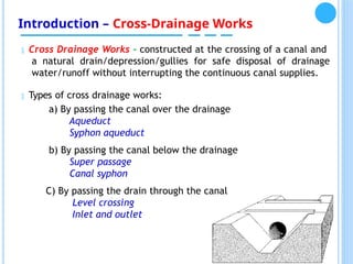
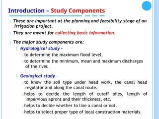
Advanced Hydraulic Structures
Course Contents
Habtamu Hailu (PhD)
(AASTU)
Course Contents:
1 Introduction
2 Diversion Head Works
3 Irrigation Canal Networks
4 Irrigation Control Structures
Course Contents:
 Chapter 1 –
Introduction
 Definition of Hydraulic
Structures
 Types and General Functions of Irrigation Hydraulic
Structures
 Study components for design of Hydraulic Structures
 Basic Design Principles of Irrigation Hydraulic Structures
 Chapter 2 – Diversion Head Works
 Types and Purposes of A Diversion Headwork
 Location and Site Selection for A Diversion Head
Work
 Components and Layout of Diversion Head Work
 Design of Weir and Barrage
 Design of canal head
regulator
Course Contents:
 Chapter 3 –Irrigation Canal
Networks
 Layout of Canal Network Structures
 Design of Alluvial and Non-alluvial
Canals
 Canal Lining and Economics of Lining
 Chapter 4 – Irrigation Control
Structures
 Design of Drop Structures/Canal Falls
 Design of Head and Cross Regulators/Division
Boxes
 Design of Cross Drainage Works
Course Contents:
REFERENCES
1. Design of Diversion Weirs by Baban R.
2. Hydraulic structures by Novak and Narayanan , Fourth Edition
3. Irrigation engineering and hydraulics structures by S. K. Garg
4. Irrigation, water power and water resources engineering by K.K Arora
5. Small Hydraulic Structures. FAO Irr and Drain Paper 26/2. 1975
Papers/Docs. Recommended for Reading :
Journal of Irrigation & Drainage Engineering. ASCE publications.
International Water Management Institute. Working Papers.
Irrigation Design - Feasibility & Detail Design Documents. WWDSE.
Course Assessment:
- Assignment (15%)
- Seminar/Project: (30%)
- Final Exam (55%) – Theory (25%); Workout (30%)
Group Seminar Presentations:
 Group 1. Irrigation Potential and Development in
Ethiopia by
Region and scale (Small, Medium, and Large
Scale).
 Group 2. Assessment on Irrigation Project Feasibility
study
components in Ethiopia – Take a case study
 Group 3. Procedures/guidelines for design of weirs and
barrage
in Ethiopia – Take a case study
 Group 4. Procedures/guidelines for Design of drop
structures in
Ethiopia - Take a case
study.
 Group 5. Procedures/guidelines for Design of cross-
drainage
works drop structures in Ethiopia - Take a case
study.
Chapter 1
INTRODUCTION
Chapter 1. Introduction
Hydraulic Structures
 Any structures that can be used to divert, restrict,
stop, or otherwise manage the natural flow of water.
 They can be made from materials ranging from large
rock and concrete to items such as wooden timbers
or
tree trunks.
Application Areas of Hydraulic Structures
 Production of power
 Water supply and sewerage system
 Irrigation schemes
 Flood protection works
 Navigation
Chapter 1. Introduction
Types of Irrigation Hydraulic Structures
 Heading up structures/Headwork structures
 Water Distribution structures/Canal Networks
 Irrigation Control Structures
 Canal Regulatory structures (Canal Falls/drop
structures, head and cross regulators, check
structures, division boxes, etc.)
 Cross-drainage Structures
Chapter 1. Introduction
WATER SOURCE COMMAND AREA
Hydraulic Structures
Head works
Network of canals
Control Structures
Introduction – Head Work Structures
 Head works - structures constructed across water courses/channels
to keep or restrict the flow of water.
 Typically two types of head works:
Storage Head Work – to store
surplus water when the river
discharge is less than the rate
of demand.
Diversion Head Work – to raise
the water level and divert the
water to the canal.
Again, the diverted water is
controlled by a canal head
regulator.
Water supplied from the
reservoir to a canal through the
canal head regulator.
E.g. Weir/ barrage
E.g. Dam
Weir and Barrages are common regulatory structures in irrigation schemes
Introduction – Canal Networks
 Canal Networks – the network of irrigation canals used to convey
water from the source to the command areas.
 Main components of canal networks include:
 Main canal – large canal which takes off from a diversion
headwork and delivers water to the branch canals (secondary
canals).
 Branch canals/Secondaries- take water from the main canal and
delivers it to the distributaries or tertiary canals.
 Distributaries/tertiaries - take off from a branch canal and
supplies water to field channels.
 Field channels – taken from the outlets of the distributary
channels by the cultivators to supply water to their own fields.
Introduction – Irrigation Control Structures
 Canal regulatory structures - to control and regulate discharges,
depth, velocity of flow in the canal.
 The important types of these structures include:
 Canal Fall/drop structures … a vertical drop structure or chute used
to modify the slope of the ground on steep lands so that it keeps the
velocity of flow in the non-erosive range.
 Canal Regulators/Division boxes…constructed at the parent/off-taking
channel so as to properly regulate/ distribute water to different
direction.
 Metering Flumes/weirs … structures constructed, usually along with
the canal regulators or division boxes, for measuring discharge.
 Check Structures … permanent or temporary structures built in the
field channel to raise the level of water by obstructing the flow in case
of insufficient flow.
 Canal Escape (optional) a side channel constructed to remove surplus
water from irrigation channel (main, distribution & branch channel)
Introduction – Cross-Drainage Works
 Cross Drainage Works - constructed at the crossing of a canal and
a natural drain/depression/gullies for safe disposal of drainage
water/runoff without interrupting the continuous canal supplies.
 Types of cross drainage works:
a) By passing the canal over the drainage
Aqueduct
Syphon aqueduct
b) By passing the canal below the drainage
Super passage
Canal syphon
C) By passing the drain through the canal
Level crossing
Inlet and outlet
Introduction – Study Components
 These are important at the planning and feasibility stage of an
irrigation project.
 They are meant for collecting basic information.
 The major study components are:
 Hydrological study –
 to determine the maximum flood level,
 to determine the minimum, mean and maximum discharges
of the river.
 Geological study –
 to know the soil type under head work, the canal head
regulator and along the canal route.
 helps to decide the length of cutoff piles, length of
impervious aprons and their thickness, etc.
 helps to decide whether to line a canal or not.
 helps to select proper type of local construction materials.
Introduction – Study Components
 Topographic study –
 T
o decide the maximum level of the command area to be
reached.
 T
o know the x-sectional and longitudinal profile of the head
work site.
 Helps to decide on the river training works by considering the
MFL.
 Helps for canal alignment and design.
 T
o decide location of crossing structures, canal falls, etc.
 Agronomical study –
 T
o know water requirement of the agricultural land whereby
the capacity of canals will be determined.
 T
o develop a land suitability map.
Introduction – Study Components
 Environmental study –
 to know the positive and negative impacts that could be
brought as a result of having the project.
E.g. to analyze the u/s and d/s effects on users.
 Socio-Economic study –
 The project should answer questions like:
 Any coherence of the farming society?
 Will the proposed structure create any conflict?
 Need for miscellaneous structure fulfilled?
Introduction – Basic Design Principles
 In hydraulic structures, there are normally two aspects of design:
 Hydraulic Aspect – determination of the water way
requirements, the shape of approaches, protection against
seepage and scour.
 Structural aspect – the design of various members to resist the
acting forces by standard structural analysis.
The acting forces principally include hydraulic forces, dead
load, earth pressures and live loads.
Introduction – Basic Design Principles
 Therefore, design of irrigation hydraulic structures shall include:
 Analysis of hydraulic failure
 Analysis of structural failure
Analysis of hydraulic failure include:
 Subsurface flow analysis
 Surface flow analysis
Analysis of structural failure include:
 Safety against sliding
 Safety against overturning
 Safety against tension
Introduction – Basic Design Principles
Analysis of hydraulic failure:
o Subsurface flow analysis… determination of the uplift pressures
exerted by seeping water and the safety of the structure against
piping.
Design Criteria:
 Thickness of the floor should be sufficient to resist uplift
 Downstream pile should be provided to prevent piping
 Suitable filter should be provided at the d/s end of the
impervious floor to prevent piping.
Method of Analysis: Lane’s, Bligh’s or Khosla’s creep theory
Introduction – Basic Design Principles
Analysis of hydraulic failure:
o Surface flow analysis … determination of the flow condition u/s
and d/s at different flow rates and to size the different parts of
the structure accordingly. E.g. In the case of weir design, crest
elevation, length and shape of weir.
Design Criteria:
 Large drop is required at d/s to dissipate energy.
 Launching apron should also be provided to keep the structure
against scouring
 Additional thickness is required at the point jump occurs to
resist suction pressure.
Method of Analysis: Hydraulic jump
Introduction – Basic Design Principles
Structural Analysis:
For a structure to be stable, the following conditions must be
fulfilled.
1. Safety against overturning:
The summation of all moments about a point must be equal to zero.
i.e. the moments which tends to topple the structure must be equal
to the moments which balances it.
But unpredictable situation likely to occur and cause the toppling
moment to exceed the balancing one and hence the structure fails.
Thus, usually a safety factor of about 1.5 to 2 is applied.
[Mbalance/ (Mtopple)] > 1.5 to 2
2. Safety against tension:
In order to avoid lifting up the structure’s heel and tension
occurrence at the base, the forces acting on the structure must
pass through the middle third of the structures base.
Introduction – Basic Design Principles
i.e. eccentricity, e<B/6 or e=/(B/2)-X/ < B/6
Where, X = M/ Vf
M = summation of all moments about the structure toe
Vf = summation of all vertical forces excluding the base reaction
X = distance of the resultant of the forces from the toe
B = width of the weir base
3. Safety against sliding:
The structure may slide in the flow direction if there is not enough
friction between the base and the foundation. T
o prevent this, the
following condition should be fulfilled.
[(Horizontal external forces)/(vertical external forces)]< f
Where, f is the friction factor between the base and the foundation
f is a function of the materials used in the construction and nature of
the foundation.
THANK YOU
RESERVOIR
DAM
Spillway
Weir and Barrage:
pond
level Shutter
Crest Level = pond level
P2=0 Crest Level
P2
P
P=P1 P1
P1 >> P2
a) Without shutter b) With shutter
Weir
pond
level
pond
level Shutter
Shutter
P2
P1
P =P2
P1=0
a) Without crest
P Crest Level
P1 << P2
b) With crest
Barrage
K e y : P = total ponding ; P1= Ponding by crest; P2= Ponding by
shutter
Small weir
Small barrage
Introduction – Head Work Structures
Introduction – Canal Networks
A complete canal system
Introduction – Drop Structures
Introduction – Division boxes
Introduction – Flow measuring devices
Parshall flume
Cut-throat flume
Triangular Weir
Introduction – Check Structures
A permanent concrete check

01 Introduction about engineering.ppt.pptx

  • 1.
    Advanced Hydraulic Structures CourseContents Habtamu Hailu (PhD) (AASTU)
  • 2.
    Course Contents: 1 Introduction 2Diversion Head Works 3 Irrigation Canal Networks 4 Irrigation Control Structures
  • 3.
    Course Contents:  Chapter1 – Introduction  Definition of Hydraulic Structures  Types and General Functions of Irrigation Hydraulic Structures  Study components for design of Hydraulic Structures  Basic Design Principles of Irrigation Hydraulic Structures  Chapter 2 – Diversion Head Works  Types and Purposes of A Diversion Headwork  Location and Site Selection for A Diversion Head Work  Components and Layout of Diversion Head Work  Design of Weir and Barrage  Design of canal head regulator
  • 4.
    Course Contents:  Chapter3 –Irrigation Canal Networks  Layout of Canal Network Structures  Design of Alluvial and Non-alluvial Canals  Canal Lining and Economics of Lining  Chapter 4 – Irrigation Control Structures  Design of Drop Structures/Canal Falls  Design of Head and Cross Regulators/Division Boxes  Design of Cross Drainage Works
  • 5.
    Course Contents: REFERENCES 1. Designof Diversion Weirs by Baban R. 2. Hydraulic structures by Novak and Narayanan , Fourth Edition 3. Irrigation engineering and hydraulics structures by S. K. Garg 4. Irrigation, water power and water resources engineering by K.K Arora 5. Small Hydraulic Structures. FAO Irr and Drain Paper 26/2. 1975 Papers/Docs. Recommended for Reading : Journal of Irrigation & Drainage Engineering. ASCE publications. International Water Management Institute. Working Papers. Irrigation Design - Feasibility & Detail Design Documents. WWDSE. Course Assessment: - Assignment (15%) - Seminar/Project: (30%) - Final Exam (55%) – Theory (25%); Workout (30%)
  • 6.
    Group Seminar Presentations: Group 1. Irrigation Potential and Development in Ethiopia by Region and scale (Small, Medium, and Large Scale).  Group 2. Assessment on Irrigation Project Feasibility study components in Ethiopia – Take a case study  Group 3. Procedures/guidelines for design of weirs and barrage in Ethiopia – Take a case study  Group 4. Procedures/guidelines for Design of drop structures in Ethiopia - Take a case study.  Group 5. Procedures/guidelines for Design of cross- drainage works drop structures in Ethiopia - Take a case study.
  • 7.
  • 8.
    Chapter 1. Introduction HydraulicStructures  Any structures that can be used to divert, restrict, stop, or otherwise manage the natural flow of water.  They can be made from materials ranging from large rock and concrete to items such as wooden timbers or tree trunks. Application Areas of Hydraulic Structures  Production of power  Water supply and sewerage system  Irrigation schemes  Flood protection works  Navigation
  • 9.
    Chapter 1. Introduction Typesof Irrigation Hydraulic Structures  Heading up structures/Headwork structures  Water Distribution structures/Canal Networks  Irrigation Control Structures  Canal Regulatory structures (Canal Falls/drop structures, head and cross regulators, check structures, division boxes, etc.)  Cross-drainage Structures
  • 10.
    Chapter 1. Introduction WATERSOURCE COMMAND AREA Hydraulic Structures Head works Network of canals Control Structures
  • 12.
    Introduction – HeadWork Structures  Head works - structures constructed across water courses/channels to keep or restrict the flow of water.  Typically two types of head works: Storage Head Work – to store surplus water when the river discharge is less than the rate of demand. Diversion Head Work – to raise the water level and divert the water to the canal. Again, the diverted water is controlled by a canal head regulator. Water supplied from the reservoir to a canal through the canal head regulator. E.g. Weir/ barrage E.g. Dam Weir and Barrages are common regulatory structures in irrigation schemes
  • 13.
    Introduction – CanalNetworks  Canal Networks – the network of irrigation canals used to convey water from the source to the command areas.  Main components of canal networks include:  Main canal – large canal which takes off from a diversion headwork and delivers water to the branch canals (secondary canals).  Branch canals/Secondaries- take water from the main canal and delivers it to the distributaries or tertiary canals.  Distributaries/tertiaries - take off from a branch canal and supplies water to field channels.  Field channels – taken from the outlets of the distributary channels by the cultivators to supply water to their own fields.
  • 14.
    Introduction – IrrigationControl Structures  Canal regulatory structures - to control and regulate discharges, depth, velocity of flow in the canal.  The important types of these structures include:  Canal Fall/drop structures … a vertical drop structure or chute used to modify the slope of the ground on steep lands so that it keeps the velocity of flow in the non-erosive range.  Canal Regulators/Division boxes…constructed at the parent/off-taking channel so as to properly regulate/ distribute water to different direction.  Metering Flumes/weirs … structures constructed, usually along with the canal regulators or division boxes, for measuring discharge.  Check Structures … permanent or temporary structures built in the field channel to raise the level of water by obstructing the flow in case of insufficient flow.  Canal Escape (optional) a side channel constructed to remove surplus water from irrigation channel (main, distribution & branch channel)
  • 15.
    Introduction – Cross-DrainageWorks  Cross Drainage Works - constructed at the crossing of a canal and a natural drain/depression/gullies for safe disposal of drainage water/runoff without interrupting the continuous canal supplies.  Types of cross drainage works: a) By passing the canal over the drainage Aqueduct Syphon aqueduct b) By passing the canal below the drainage Super passage Canal syphon C) By passing the drain through the canal Level crossing Inlet and outlet
  • 16.
    Introduction – StudyComponents  These are important at the planning and feasibility stage of an irrigation project.  They are meant for collecting basic information.  The major study components are:  Hydrological study –  to determine the maximum flood level,  to determine the minimum, mean and maximum discharges of the river.  Geological study –  to know the soil type under head work, the canal head regulator and along the canal route.  helps to decide the length of cutoff piles, length of impervious aprons and their thickness, etc.  helps to decide whether to line a canal or not.  helps to select proper type of local construction materials.
  • 17.
    Introduction – StudyComponents  Topographic study –  T o decide the maximum level of the command area to be reached.  T o know the x-sectional and longitudinal profile of the head work site.  Helps to decide on the river training works by considering the MFL.  Helps for canal alignment and design.  T o decide location of crossing structures, canal falls, etc.  Agronomical study –  T o know water requirement of the agricultural land whereby the capacity of canals will be determined.  T o develop a land suitability map.
  • 18.
    Introduction – StudyComponents  Environmental study –  to know the positive and negative impacts that could be brought as a result of having the project. E.g. to analyze the u/s and d/s effects on users.  Socio-Economic study –  The project should answer questions like:  Any coherence of the farming society?  Will the proposed structure create any conflict?  Need for miscellaneous structure fulfilled?
  • 19.
    Introduction – BasicDesign Principles  In hydraulic structures, there are normally two aspects of design:  Hydraulic Aspect – determination of the water way requirements, the shape of approaches, protection against seepage and scour.  Structural aspect – the design of various members to resist the acting forces by standard structural analysis. The acting forces principally include hydraulic forces, dead load, earth pressures and live loads.
  • 20.
    Introduction – BasicDesign Principles  Therefore, design of irrigation hydraulic structures shall include:  Analysis of hydraulic failure  Analysis of structural failure Analysis of hydraulic failure include:  Subsurface flow analysis  Surface flow analysis Analysis of structural failure include:  Safety against sliding  Safety against overturning  Safety against tension
  • 21.
    Introduction – BasicDesign Principles Analysis of hydraulic failure: o Subsurface flow analysis… determination of the uplift pressures exerted by seeping water and the safety of the structure against piping. Design Criteria:  Thickness of the floor should be sufficient to resist uplift  Downstream pile should be provided to prevent piping  Suitable filter should be provided at the d/s end of the impervious floor to prevent piping. Method of Analysis: Lane’s, Bligh’s or Khosla’s creep theory
  • 22.
    Introduction – BasicDesign Principles Analysis of hydraulic failure: o Surface flow analysis … determination of the flow condition u/s and d/s at different flow rates and to size the different parts of the structure accordingly. E.g. In the case of weir design, crest elevation, length and shape of weir. Design Criteria:  Large drop is required at d/s to dissipate energy.  Launching apron should also be provided to keep the structure against scouring  Additional thickness is required at the point jump occurs to resist suction pressure. Method of Analysis: Hydraulic jump
  • 23.
    Introduction – BasicDesign Principles Structural Analysis: For a structure to be stable, the following conditions must be fulfilled. 1. Safety against overturning: The summation of all moments about a point must be equal to zero. i.e. the moments which tends to topple the structure must be equal to the moments which balances it. But unpredictable situation likely to occur and cause the toppling moment to exceed the balancing one and hence the structure fails. Thus, usually a safety factor of about 1.5 to 2 is applied. [Mbalance/ (Mtopple)] > 1.5 to 2 2. Safety against tension: In order to avoid lifting up the structure’s heel and tension occurrence at the base, the forces acting on the structure must pass through the middle third of the structures base.
  • 24.
    Introduction – BasicDesign Principles i.e. eccentricity, e<B/6 or e=/(B/2)-X/ < B/6 Where, X = M/ Vf M = summation of all moments about the structure toe Vf = summation of all vertical forces excluding the base reaction X = distance of the resultant of the forces from the toe B = width of the weir base 3. Safety against sliding: The structure may slide in the flow direction if there is not enough friction between the base and the foundation. T o prevent this, the following condition should be fulfilled. [(Horizontal external forces)/(vertical external forces)]< f Where, f is the friction factor between the base and the foundation f is a function of the materials used in the construction and nature of the foundation.
  • 25.
  • 26.
  • 27.
    Weir and Barrage: pond levelShutter Crest Level = pond level P2=0 Crest Level P2 P P=P1 P1 P1 >> P2 a) Without shutter b) With shutter Weir pond level pond level Shutter Shutter P2 P1 P =P2 P1=0 a) Without crest P Crest Level P1 << P2 b) With crest Barrage K e y : P = total ponding ; P1= Ponding by crest; P2= Ponding by shutter
  • 28.
  • 29.
    Introduction – HeadWork Structures
  • 30.
    Introduction – CanalNetworks A complete canal system
  • 31.
  • 32.
  • 33.
    Introduction – Flowmeasuring devices Parshall flume Cut-throat flume Triangular Weir
  • 34.
    Introduction – CheckStructures A permanent concrete check