SlideShare a Scribd company logo
1 of 1
Poster Design & Printing by Genigraphics® - 800.790.4001
Comparison between flow configurations of Shell and Tube Heat Exchanger
Ammarah Hasan, Amna Iqbal*, Asma Zaidy, Sidra Hafeez
B.Sc. Chemical Engineering, Semester – VI (Session – 2008)
Department of Chemical Engineering and Technology, UET (KSK-Campus), Lahore - Pakistan
INTRODUCTION
METHODS AND MATERIALS
ACKNOWLEDGEMENT
RESULTS
REFERENCES
ABSTRACT
*CORRESPONDENT AUTHOR
Email:amnaiqbal46@yahoo.com
The objective of this study is to determine
the effectiveness of the flow
configurations. The study was done on 1-
1 shell and tube heat exchanger at
optimized temperature i.e. 43.5 oC.
Highest efficiency for co-current
configuration was obtained at 43.5o C with
inlet cold fluid flow rate i.e.1.21 kg/min
and hot fluid flow rate i.e. 2.5 kg/min. For
countercurrent configurations, highest
efficiency was obtained at 43.5 oC with
inlet hot fluid flow rate i.e. 2.25 kg/min and
cold fluid flow rate i.e. 1.49 kg/min.
Results obtained from experiment proved
that shell and tube heat exchanger
provides more efficiency in counter
current configuration.
Keywords: Optimized, Configuration,
Shell and Tube ,Co-current, Counter
Current, Efficiency.
In this study, the performance evaluation of shell and tube
heat exchanger for co-current and countercurrent
configurations are carried out on 1-1 shell and tube heat
exchanger of 20,000 mm2 area, having seven fixed
stainless steel tubes (do = 6.35 mm), polymeric material
(acrylic) shell and two transverse segmental baffles with
25% cut (Armfield, 2004).
Methodology to evaluate the performance of shell and tube
heat exchanger in co-current and countercurrent
configurations is developed as:
Connected the water supply in counter current
configuration. Allocated the cold fluid 1l/min to shell side
and hot fluid 2 l/min to tube side. By keeping these flow
rates constant, optimized hot fluid inlet temperature was
calculated. At this optimum temperature by keeping the flow
rates constant highest efficiency for countercurrent was
calculated. Repeated the same procedure for co-current
configuration (Armfield,2004).
In case of counter current, Efficiency is calculated as:
Co-current, Efficiency is calculated as:
The research work would not be possible without the
encouragement of Prof. Dr. Zafar Noon and Mr. Izzat Iqbal
Cheema. Ikram-ul-Haq and Nadeem Akhtar helped us by
providing related data in lab work.
Finally, we also thank our parents for providing us
every type of support and encouragement.
Heat exchangers are ubiquitous to energy conversion and
utilization. They involve heat exchange between two fluids
separated by a solid and encompass a wide range of flow
configurations.
Shell and tube heat exchanger provides large ratio of heat
transfer area to volume and weight (John,2004). Basic
nomenclature and classification scheme for shell and tube
heat exchanger provided by Tubular Exchanger
Manufacturers Association(TEMA). According to TEMA
standard nomenclature, first latter describe the head type at
the front end‟A’: the second letter, the shell type‟E’: and the
third letter, the head type at the rear end‟L’ of the exchanger
(Peters et al., 2003).This is widely used for liquid/liquid heat
transfer accounting for at least 60 percent of all heat
exchangers used in process industry and 95 percent in
petroleum industries (Peters et al., 2003).
The tubes are the basic component of shell and tube heat
exchanger, providing the heat transfer surface between one
fluid flowing inside and the other fluid flowing outside of the
tubes(John, 2004).Fluid is allocated on the basis of
corrosion, operating pressure, fouling, fluid temperature,
pressure drop, viscosity and stream flow
rates(Sinnott,2003).The operating ranges for shell and tube
heat exchanger are up to 30 Mpa and -200 to 600 oC
(Peters et al.,2003).Common applications includes:
space heating, air conditioning, refrigeration, natural gas
processing, power plants, petroleum refineries, chemical
plants(Shankar 2007).
John R.T., “Wolverine Tube Heat Transfer Data Book”, 2004.
Peters M. S., Timmerhaus K. D., West R. E. “Plant Design
and Economics for Chemical Engineers” Ed.5, McGraw-
Hill Publishers Inc.
Perry R.H., Green D.W.,“Perry„s Chemical Engineer„s
Handbook“ 7th Ed.1997.
Shankar R. S.,“Shell and Tube Heat Exchangers“July
16,2007.
Sinnott R.K, “Chemical Engineering Design” , Vol. 6, Ed. 4,
Butterworth Heinemann Publishers Inc.
http://www.discoverarmfield.co.uk/data/ht30xc/ht3237.php,
April 15,2011.
Results obtained from study were used to compare
effectiveness of shell and tube heat exchanger for
countercurrent and co-current configuration.
Below graphs depict relation of exchanger effectiveness verses
various parameters (i.e. hot fluid flow rate, cold fluid flow rate
and inlet temperature of hot fluid). With aid of these graphs,
optimized temperature of hot fluid at inlet for both configurations
is calculated i.e. 43.5 oC for this particular exchanger (Figure 1).
Comparison of co-current and countercurrent configurations at
optimized temperature gives optimized hot fluid mass flow
rates i.e. 2.5 kg/min and 2.25 kg/min respectively (Figure 2). At
this optimized hot fluid flow rate, optimized cold fluid flow rate is
evaluated for co-current and counter current configurations as
1.21kg/min and 1.49kg/min respectively (Figure 3).
Figure 2.Hot Fluid Flow Rate (kg/min) vs Efficiency(%) at Optimum Temperature
Figure 3.Cold Fluid Flow Rate (kg/min) vs Efficiency (%) at Optimum Temperature
Figure 1.Temperature (oC) vs Efficiency(%) at constant flow rate
The effectiveness of shell and tube heat exchangers
generally is between 0.4 and 0.8 depending on the
configuration (Peters et al., 2003). Experimental results
reveal that the efficiency of countercurrent configuration
is more than the co-current due to more contact area
between two fluids (Sinnott,2003). As the flow rates are
increased, efficiency is increased (Figure 2,3). At the input
end, there is a large temperature difference and lots of
heat transfer; at the output end, small temperature
difference, and little heat transfer. It shows that efficiency is
maximum at the input and after reaching at optimum point,
it shows decreasing trend (Perry’s et al.,1997).
Another factor that accounts for increasing efficiency is the
corrugation of the tube bundles that effects the overall
performance of the heat exchanger. The tube bundles fold
or wrinkle will increase liquid flow, thereby facilitating heat
transfer, resulting in a more efficient and accurate
performance from the heat exchanger.
Maximum efficiencies at optimum conditions for co-current
and countercurrent configurations are calculated i.e. 42%
and 78% respectively.
Symbol Description Units
Th1 Hot fluid inlet temperature oC
Th2 Hot fluid outlet temperature oC
Tc1 Cold fluid inlet temperature oC
Tc2 Cold fluid outlet temperature oC
Ƞh Efficiency of hot fluid %
Ƞc Efficiency of cold fluid %
mc Cold fluid flow rate kg/min
mh Hot fluid flow rate kg/min
0
10
20
30
40
50
60
70
80
90
1.5 1.7 1.9 2.1 2.3 2.5 2.7 2.9
Efficiency,ηh(%)
Hot Fluid Flow Rate ‘mc’(kg/min)
Counter Current Configuration Co-Current Configuration
0
1
2
3
4
5
6
7
8
9
10
35 40 45 50 55 60
Efficiency,η(%)
Temperature,Th1(oC)
Co-Current Configuration Counter Current Configuration
DISCUSSION
NOMENCLATURE
)2(
11
12
ch
cc
c
TT
TT
)3(
12
12
ch
hh
TT
TT
h )4(
12
12
ch
cc
c
TT
TT
)1(
12
12
ch
hh
TT
TT
h
0
10
20
30
40
50
60
70
80
1.06 1.16 1.26 1.36 1.46 1.56 1.66
Efficiency,Ƞc(%)
Cold Fluid Flow Rate ‘mc’(kg/min)
Co-Current Configuration Counter Current Configuration

More Related Content

What's hot

Computational Performance Analysis of Heat Sink with Pin Fin for Various Surf...
Computational Performance Analysis of Heat Sink with Pin Fin for Various Surf...Computational Performance Analysis of Heat Sink with Pin Fin for Various Surf...
Computational Performance Analysis of Heat Sink with Pin Fin for Various Surf...IRJET Journal
 
IRJET- Effect of Wavy Tube on Heat Transfer in a Concentric Tube Heat Exch...
IRJET- 	  Effect of Wavy Tube on Heat Transfer in a Concentric Tube Heat Exch...IRJET- 	  Effect of Wavy Tube on Heat Transfer in a Concentric Tube Heat Exch...
IRJET- Effect of Wavy Tube on Heat Transfer in a Concentric Tube Heat Exch...IRJET Journal
 
Analysis of Natural Convention Heat Transfer Enhancement in Finned Tube Heat ...
Analysis of Natural Convention Heat Transfer Enhancement in Finned Tube Heat ...Analysis of Natural Convention Heat Transfer Enhancement in Finned Tube Heat ...
Analysis of Natural Convention Heat Transfer Enhancement in Finned Tube Heat ...journal ijrtem
 
EXPERIMENTAL STUDY ON THE ANALYSIS OF HEAT ENHANCEMENT IN CORRUGATED TWISTED ...
EXPERIMENTAL STUDY ON THE ANALYSIS OF HEAT ENHANCEMENT IN CORRUGATED TWISTED ...EXPERIMENTAL STUDY ON THE ANALYSIS OF HEAT ENHANCEMENT IN CORRUGATED TWISTED ...
EXPERIMENTAL STUDY ON THE ANALYSIS OF HEAT ENHANCEMENT IN CORRUGATED TWISTED ...P singh
 
Numerical simulation and enhancement of heat transfer using cuo water nano fl...
Numerical simulation and enhancement of heat transfer using cuo water nano fl...Numerical simulation and enhancement of heat transfer using cuo water nano fl...
Numerical simulation and enhancement of heat transfer using cuo water nano fl...IAEME Publication
 
A Review on Enhancement of Heat Transfer Rate by Various Passive Methods
A Review on Enhancement of Heat Transfer Rate by Various Passive MethodsA Review on Enhancement of Heat Transfer Rate by Various Passive Methods
A Review on Enhancement of Heat Transfer Rate by Various Passive MethodsIRJET Journal
 
Experimental Investigation on Heat Transfer Analysis in a Cross flow Heat Ex...
Experimental Investigation on Heat Transfer Analysis in a Cross  flow Heat Ex...Experimental Investigation on Heat Transfer Analysis in a Cross  flow Heat Ex...
Experimental Investigation on Heat Transfer Analysis in a Cross flow Heat Ex...IJMER
 
Experimental study of heat transfer
Experimental study of heat transferExperimental study of heat transfer
Experimental study of heat transferprj_publication
 
Experimental analysis of partial and fully charged thermal stratified hot wat...
Experimental analysis of partial and fully charged thermal stratified hot wat...Experimental analysis of partial and fully charged thermal stratified hot wat...
Experimental analysis of partial and fully charged thermal stratified hot wat...IAEME Publication
 
Experimental Investigation on Heat Transfer By Natural Convection Over A Cyli...
Experimental Investigation on Heat Transfer By Natural Convection Over A Cyli...Experimental Investigation on Heat Transfer By Natural Convection Over A Cyli...
Experimental Investigation on Heat Transfer By Natural Convection Over A Cyli...Ijripublishers Ijri
 
Paper id 21201420
Paper id 21201420Paper id 21201420
Paper id 21201420IJRAT
 
Analytical and Experimental analysis ofthermal characteristics throughTriangu...
Analytical and Experimental analysis ofthermal characteristics throughTriangu...Analytical and Experimental analysis ofthermal characteristics throughTriangu...
Analytical and Experimental analysis ofthermal characteristics throughTriangu...IJERA Editor
 

What's hot (16)

Computational Performance Analysis of Heat Sink with Pin Fin for Various Surf...
Computational Performance Analysis of Heat Sink with Pin Fin for Various Surf...Computational Performance Analysis of Heat Sink with Pin Fin for Various Surf...
Computational Performance Analysis of Heat Sink with Pin Fin for Various Surf...
 
IRJET- Effect of Wavy Tube on Heat Transfer in a Concentric Tube Heat Exch...
IRJET- 	  Effect of Wavy Tube on Heat Transfer in a Concentric Tube Heat Exch...IRJET- 	  Effect of Wavy Tube on Heat Transfer in a Concentric Tube Heat Exch...
IRJET- Effect of Wavy Tube on Heat Transfer in a Concentric Tube Heat Exch...
 
30120140507006
3012014050700630120140507006
30120140507006
 
Ld35191119013
Ld35191119013Ld35191119013
Ld35191119013
 
Analysis of Natural Convention Heat Transfer Enhancement in Finned Tube Heat ...
Analysis of Natural Convention Heat Transfer Enhancement in Finned Tube Heat ...Analysis of Natural Convention Heat Transfer Enhancement in Finned Tube Heat ...
Analysis of Natural Convention Heat Transfer Enhancement in Finned Tube Heat ...
 
EXPERIMENTAL STUDY ON THE ANALYSIS OF HEAT ENHANCEMENT IN CORRUGATED TWISTED ...
EXPERIMENTAL STUDY ON THE ANALYSIS OF HEAT ENHANCEMENT IN CORRUGATED TWISTED ...EXPERIMENTAL STUDY ON THE ANALYSIS OF HEAT ENHANCEMENT IN CORRUGATED TWISTED ...
EXPERIMENTAL STUDY ON THE ANALYSIS OF HEAT ENHANCEMENT IN CORRUGATED TWISTED ...
 
Numerical simulation and enhancement of heat transfer using cuo water nano fl...
Numerical simulation and enhancement of heat transfer using cuo water nano fl...Numerical simulation and enhancement of heat transfer using cuo water nano fl...
Numerical simulation and enhancement of heat transfer using cuo water nano fl...
 
A Review on Enhancement of Heat Transfer Rate by Various Passive Methods
A Review on Enhancement of Heat Transfer Rate by Various Passive MethodsA Review on Enhancement of Heat Transfer Rate by Various Passive Methods
A Review on Enhancement of Heat Transfer Rate by Various Passive Methods
 
Ijmet 10 01_108
Ijmet 10 01_108Ijmet 10 01_108
Ijmet 10 01_108
 
Experimental Investigation on Heat Transfer Analysis in a Cross flow Heat Ex...
Experimental Investigation on Heat Transfer Analysis in a Cross  flow Heat Ex...Experimental Investigation on Heat Transfer Analysis in a Cross  flow Heat Ex...
Experimental Investigation on Heat Transfer Analysis in a Cross flow Heat Ex...
 
Experimental study of heat transfer
Experimental study of heat transferExperimental study of heat transfer
Experimental study of heat transfer
 
Experimental analysis of partial and fully charged thermal stratified hot wat...
Experimental analysis of partial and fully charged thermal stratified hot wat...Experimental analysis of partial and fully charged thermal stratified hot wat...
Experimental analysis of partial and fully charged thermal stratified hot wat...
 
Experimental Investigation on Heat Transfer By Natural Convection Over A Cyli...
Experimental Investigation on Heat Transfer By Natural Convection Over A Cyli...Experimental Investigation on Heat Transfer By Natural Convection Over A Cyli...
Experimental Investigation on Heat Transfer By Natural Convection Over A Cyli...
 
Paper id 21201420
Paper id 21201420Paper id 21201420
Paper id 21201420
 
Analytical and Experimental analysis ofthermal characteristics throughTriangu...
Analytical and Experimental analysis ofthermal characteristics throughTriangu...Analytical and Experimental analysis ofthermal characteristics throughTriangu...
Analytical and Experimental analysis ofthermal characteristics throughTriangu...
 
E351923
E351923E351923
E351923
 

Similar to Comparison between flow configurations of a shell and tube heat exchanger

AN EXPERIMENTAL STUDY OF EXERGY IN A CORRUGATED PLATE HEAT EXCHANGER
  AN EXPERIMENTAL STUDY OF EXERGY IN A CORRUGATED PLATE HEAT EXCHANGER  AN EXPERIMENTAL STUDY OF EXERGY IN A CORRUGATED PLATE HEAT EXCHANGER
AN EXPERIMENTAL STUDY OF EXERGY IN A CORRUGATED PLATE HEAT EXCHANGERIAEME Publication
 
Heat Transfer Analysis of a Biomimetic Plate Heat Exchanger with Bird Feather...
Heat Transfer Analysis of a Biomimetic Plate Heat Exchanger with Bird Feather...Heat Transfer Analysis of a Biomimetic Plate Heat Exchanger with Bird Feather...
Heat Transfer Analysis of a Biomimetic Plate Heat Exchanger with Bird Feather...IRJET Journal
 
HEAT TRANSFER AUGMENTATION IN A PLATE-FIN HEAT EXCHANGER: A REVIEW
  HEAT TRANSFER AUGMENTATION IN A PLATE-FIN HEAT EXCHANGER: A REVIEW  HEAT TRANSFER AUGMENTATION IN A PLATE-FIN HEAT EXCHANGER: A REVIEW
HEAT TRANSFER AUGMENTATION IN A PLATE-FIN HEAT EXCHANGER: A REVIEWIAEME Publication
 
Comparison of Shell and Tube Heat Exchanger using Theoretical Methods, HTRI, ...
Comparison of Shell and Tube Heat Exchanger using Theoretical Methods, HTRI, ...Comparison of Shell and Tube Heat Exchanger using Theoretical Methods, HTRI, ...
Comparison of Shell and Tube Heat Exchanger using Theoretical Methods, HTRI, ...IJERA Editor
 
HEAT TRANSFER CO EFFICIENT VS HEAT FLOW RATE BY FORCED CONVECTION
HEAT TRANSFER CO EFFICIENT VS HEAT FLOW RATE BY FORCED CONVECTIONHEAT TRANSFER CO EFFICIENT VS HEAT FLOW RATE BY FORCED CONVECTION
HEAT TRANSFER CO EFFICIENT VS HEAT FLOW RATE BY FORCED CONVECTIONTajammul Kamal
 
Comparative Study and Analysis between Helical Coil and Straight Tube Heat Ex...
Comparative Study and Analysis between Helical Coil and Straight Tube Heat Ex...Comparative Study and Analysis between Helical Coil and Straight Tube Heat Ex...
Comparative Study and Analysis between Helical Coil and Straight Tube Heat Ex...IJERA Editor
 
AN EXPERIMENTAL STUDY OF HEAT TRANSFER IN A CORRUGATED PLATE HEAT EXCHANGER
AN EXPERIMENTAL STUDY OF HEAT TRANSFER IN A CORRUGATED PLATE HEAT EXCHANGER AN EXPERIMENTAL STUDY OF HEAT TRANSFER IN A CORRUGATED PLATE HEAT EXCHANGER
AN EXPERIMENTAL STUDY OF HEAT TRANSFER IN A CORRUGATED PLATE HEAT EXCHANGER IAEME Publication
 
Experimental Study of Heat Transfer Enhancement of Pipe-inPipe Helical Coil H...
Experimental Study of Heat Transfer Enhancement of Pipe-inPipe Helical Coil H...Experimental Study of Heat Transfer Enhancement of Pipe-inPipe Helical Coil H...
Experimental Study of Heat Transfer Enhancement of Pipe-inPipe Helical Coil H...iosrjce
 
Analysis of Double Pipe Heat Exchanger With Helical Fins
Analysis of Double Pipe Heat Exchanger With Helical FinsAnalysis of Double Pipe Heat Exchanger With Helical Fins
Analysis of Double Pipe Heat Exchanger With Helical FinsIRJET Journal
 
NUMERICAL INVESTIGATION OF AUTOMOTIVE RADIATOR LOUVERED FIN COMPACT HEAT EXCH...
NUMERICAL INVESTIGATION OF AUTOMOTIVE RADIATOR LOUVERED FIN COMPACT HEAT EXCH...NUMERICAL INVESTIGATION OF AUTOMOTIVE RADIATOR LOUVERED FIN COMPACT HEAT EXCH...
NUMERICAL INVESTIGATION OF AUTOMOTIVE RADIATOR LOUVERED FIN COMPACT HEAT EXCH...IAEME Publication
 
Experimental Investigation of Brazed Plate Heat Exchanger for Small Temperatu...
Experimental Investigation of Brazed Plate Heat Exchanger for Small Temperatu...Experimental Investigation of Brazed Plate Heat Exchanger for Small Temperatu...
Experimental Investigation of Brazed Plate Heat Exchanger for Small Temperatu...IRJET Journal
 
ESTIMATION AND ANALYSIS OF CYCLE EFFICIENCY FOR SHELL AND TUBE HEAT EXCHANGER...
ESTIMATION AND ANALYSIS OF CYCLE EFFICIENCY FOR SHELL AND TUBE HEAT EXCHANGER...ESTIMATION AND ANALYSIS OF CYCLE EFFICIENCY FOR SHELL AND TUBE HEAT EXCHANGER...
ESTIMATION AND ANALYSIS OF CYCLE EFFICIENCY FOR SHELL AND TUBE HEAT EXCHANGER...IAEME Publication
 
A Detailed Review on Artificial Roughness Geometries for Optimizing Thermo-Hy...
A Detailed Review on Artificial Roughness Geometries for Optimizing Thermo-Hy...A Detailed Review on Artificial Roughness Geometries for Optimizing Thermo-Hy...
A Detailed Review on Artificial Roughness Geometries for Optimizing Thermo-Hy...IJMER
 
An experimental study of heat transfer in a corrugated plate heat exchanger
An experimental study of heat transfer in a corrugated plate heat exchangerAn experimental study of heat transfer in a corrugated plate heat exchanger
An experimental study of heat transfer in a corrugated plate heat exchangerIAEME Publication
 

Similar to Comparison between flow configurations of a shell and tube heat exchanger (20)

AN EXPERIMENTAL STUDY OF EXERGY IN A CORRUGATED PLATE HEAT EXCHANGER
  AN EXPERIMENTAL STUDY OF EXERGY IN A CORRUGATED PLATE HEAT EXCHANGER  AN EXPERIMENTAL STUDY OF EXERGY IN A CORRUGATED PLATE HEAT EXCHANGER
AN EXPERIMENTAL STUDY OF EXERGY IN A CORRUGATED PLATE HEAT EXCHANGER
 
Heat Transfer Analysis of a Biomimetic Plate Heat Exchanger with Bird Feather...
Heat Transfer Analysis of a Biomimetic Plate Heat Exchanger with Bird Feather...Heat Transfer Analysis of a Biomimetic Plate Heat Exchanger with Bird Feather...
Heat Transfer Analysis of a Biomimetic Plate Heat Exchanger with Bird Feather...
 
HEAT TRANSFER AUGMENTATION IN A PLATE-FIN HEAT EXCHANGER: A REVIEW
  HEAT TRANSFER AUGMENTATION IN A PLATE-FIN HEAT EXCHANGER: A REVIEW  HEAT TRANSFER AUGMENTATION IN A PLATE-FIN HEAT EXCHANGER: A REVIEW
HEAT TRANSFER AUGMENTATION IN A PLATE-FIN HEAT EXCHANGER: A REVIEW
 
Comparison of Shell and Tube Heat Exchanger using Theoretical Methods, HTRI, ...
Comparison of Shell and Tube Heat Exchanger using Theoretical Methods, HTRI, ...Comparison of Shell and Tube Heat Exchanger using Theoretical Methods, HTRI, ...
Comparison of Shell and Tube Heat Exchanger using Theoretical Methods, HTRI, ...
 
HEAT TRANSFER CO EFFICIENT VS HEAT FLOW RATE BY FORCED CONVECTION
HEAT TRANSFER CO EFFICIENT VS HEAT FLOW RATE BY FORCED CONVECTIONHEAT TRANSFER CO EFFICIENT VS HEAT FLOW RATE BY FORCED CONVECTION
HEAT TRANSFER CO EFFICIENT VS HEAT FLOW RATE BY FORCED CONVECTION
 
Comparative Study and Analysis between Helical Coil and Straight Tube Heat Ex...
Comparative Study and Analysis between Helical Coil and Straight Tube Heat Ex...Comparative Study and Analysis between Helical Coil and Straight Tube Heat Ex...
Comparative Study and Analysis between Helical Coil and Straight Tube Heat Ex...
 
AN EXPERIMENTAL STUDY OF HEAT TRANSFER IN A CORRUGATED PLATE HEAT EXCHANGER
AN EXPERIMENTAL STUDY OF HEAT TRANSFER IN A CORRUGATED PLATE HEAT EXCHANGER AN EXPERIMENTAL STUDY OF HEAT TRANSFER IN A CORRUGATED PLATE HEAT EXCHANGER
AN EXPERIMENTAL STUDY OF HEAT TRANSFER IN A CORRUGATED PLATE HEAT EXCHANGER
 
M012628386
M012628386M012628386
M012628386
 
Experimental Study of Heat Transfer Enhancement of Pipe-inPipe Helical Coil H...
Experimental Study of Heat Transfer Enhancement of Pipe-inPipe Helical Coil H...Experimental Study of Heat Transfer Enhancement of Pipe-inPipe Helical Coil H...
Experimental Study of Heat Transfer Enhancement of Pipe-inPipe Helical Coil H...
 
M012628386
M012628386M012628386
M012628386
 
W04405127131
W04405127131W04405127131
W04405127131
 
Analysis of Double Pipe Heat Exchanger With Helical Fins
Analysis of Double Pipe Heat Exchanger With Helical FinsAnalysis of Double Pipe Heat Exchanger With Helical Fins
Analysis of Double Pipe Heat Exchanger With Helical Fins
 
30120140507001
3012014050700130120140507001
30120140507001
 
30120130405019 2
30120130405019 230120130405019 2
30120130405019 2
 
NUMERICAL INVESTIGATION OF AUTOMOTIVE RADIATOR LOUVERED FIN COMPACT HEAT EXCH...
NUMERICAL INVESTIGATION OF AUTOMOTIVE RADIATOR LOUVERED FIN COMPACT HEAT EXCH...NUMERICAL INVESTIGATION OF AUTOMOTIVE RADIATOR LOUVERED FIN COMPACT HEAT EXCH...
NUMERICAL INVESTIGATION OF AUTOMOTIVE RADIATOR LOUVERED FIN COMPACT HEAT EXCH...
 
Experimental Investigation of Brazed Plate Heat Exchanger for Small Temperatu...
Experimental Investigation of Brazed Plate Heat Exchanger for Small Temperatu...Experimental Investigation of Brazed Plate Heat Exchanger for Small Temperatu...
Experimental Investigation of Brazed Plate Heat Exchanger for Small Temperatu...
 
ESTIMATION AND ANALYSIS OF CYCLE EFFICIENCY FOR SHELL AND TUBE HEAT EXCHANGER...
ESTIMATION AND ANALYSIS OF CYCLE EFFICIENCY FOR SHELL AND TUBE HEAT EXCHANGER...ESTIMATION AND ANALYSIS OF CYCLE EFFICIENCY FOR SHELL AND TUBE HEAT EXCHANGER...
ESTIMATION AND ANALYSIS OF CYCLE EFFICIENCY FOR SHELL AND TUBE HEAT EXCHANGER...
 
A Detailed Review on Artificial Roughness Geometries for Optimizing Thermo-Hy...
A Detailed Review on Artificial Roughness Geometries for Optimizing Thermo-Hy...A Detailed Review on Artificial Roughness Geometries for Optimizing Thermo-Hy...
A Detailed Review on Artificial Roughness Geometries for Optimizing Thermo-Hy...
 
An experimental study of heat transfer in a corrugated plate heat exchanger
An experimental study of heat transfer in a corrugated plate heat exchangerAn experimental study of heat transfer in a corrugated plate heat exchanger
An experimental study of heat transfer in a corrugated plate heat exchanger
 
30120140506001
3012014050600130120140506001
30120140506001
 

Comparison between flow configurations of a shell and tube heat exchanger

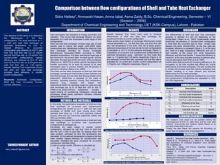
  • 1. Poster Design & Printing by Genigraphics® - 800.790.4001 Comparison between flow configurations of Shell and Tube Heat Exchanger Ammarah Hasan, Amna Iqbal*, Asma Zaidy, Sidra Hafeez B.Sc. Chemical Engineering, Semester – VI (Session – 2008) Department of Chemical Engineering and Technology, UET (KSK-Campus), Lahore - Pakistan INTRODUCTION METHODS AND MATERIALS ACKNOWLEDGEMENT RESULTS REFERENCES ABSTRACT *CORRESPONDENT AUTHOR Email:amnaiqbal46@yahoo.com The objective of this study is to determine the effectiveness of the flow configurations. The study was done on 1- 1 shell and tube heat exchanger at optimized temperature i.e. 43.5 oC. Highest efficiency for co-current configuration was obtained at 43.5o C with inlet cold fluid flow rate i.e.1.21 kg/min and hot fluid flow rate i.e. 2.5 kg/min. For countercurrent configurations, highest efficiency was obtained at 43.5 oC with inlet hot fluid flow rate i.e. 2.25 kg/min and cold fluid flow rate i.e. 1.49 kg/min. Results obtained from experiment proved that shell and tube heat exchanger provides more efficiency in counter current configuration. Keywords: Optimized, Configuration, Shell and Tube ,Co-current, Counter Current, Efficiency. In this study, the performance evaluation of shell and tube heat exchanger for co-current and countercurrent configurations are carried out on 1-1 shell and tube heat exchanger of 20,000 mm2 area, having seven fixed stainless steel tubes (do = 6.35 mm), polymeric material (acrylic) shell and two transverse segmental baffles with 25% cut (Armfield, 2004). Methodology to evaluate the performance of shell and tube heat exchanger in co-current and countercurrent configurations is developed as: Connected the water supply in counter current configuration. Allocated the cold fluid 1l/min to shell side and hot fluid 2 l/min to tube side. By keeping these flow rates constant, optimized hot fluid inlet temperature was calculated. At this optimum temperature by keeping the flow rates constant highest efficiency for countercurrent was calculated. Repeated the same procedure for co-current configuration (Armfield,2004). In case of counter current, Efficiency is calculated as: Co-current, Efficiency is calculated as: The research work would not be possible without the encouragement of Prof. Dr. Zafar Noon and Mr. Izzat Iqbal Cheema. Ikram-ul-Haq and Nadeem Akhtar helped us by providing related data in lab work. Finally, we also thank our parents for providing us every type of support and encouragement. Heat exchangers are ubiquitous to energy conversion and utilization. They involve heat exchange between two fluids separated by a solid and encompass a wide range of flow configurations. Shell and tube heat exchanger provides large ratio of heat transfer area to volume and weight (John,2004). Basic nomenclature and classification scheme for shell and tube heat exchanger provided by Tubular Exchanger Manufacturers Association(TEMA). According to TEMA standard nomenclature, first latter describe the head type at the front end‟A’: the second letter, the shell type‟E’: and the third letter, the head type at the rear end‟L’ of the exchanger (Peters et al., 2003).This is widely used for liquid/liquid heat transfer accounting for at least 60 percent of all heat exchangers used in process industry and 95 percent in petroleum industries (Peters et al., 2003). The tubes are the basic component of shell and tube heat exchanger, providing the heat transfer surface between one fluid flowing inside and the other fluid flowing outside of the tubes(John, 2004).Fluid is allocated on the basis of corrosion, operating pressure, fouling, fluid temperature, pressure drop, viscosity and stream flow rates(Sinnott,2003).The operating ranges for shell and tube heat exchanger are up to 30 Mpa and -200 to 600 oC (Peters et al.,2003).Common applications includes: space heating, air conditioning, refrigeration, natural gas processing, power plants, petroleum refineries, chemical plants(Shankar 2007). John R.T., “Wolverine Tube Heat Transfer Data Book”, 2004. Peters M. S., Timmerhaus K. D., West R. E. “Plant Design and Economics for Chemical Engineers” Ed.5, McGraw- Hill Publishers Inc. Perry R.H., Green D.W.,“Perry„s Chemical Engineer„s Handbook“ 7th Ed.1997. Shankar R. S.,“Shell and Tube Heat Exchangers“July 16,2007. Sinnott R.K, “Chemical Engineering Design” , Vol. 6, Ed. 4, Butterworth Heinemann Publishers Inc. http://www.discoverarmfield.co.uk/data/ht30xc/ht3237.php, April 15,2011. Results obtained from study were used to compare effectiveness of shell and tube heat exchanger for countercurrent and co-current configuration. Below graphs depict relation of exchanger effectiveness verses various parameters (i.e. hot fluid flow rate, cold fluid flow rate and inlet temperature of hot fluid). With aid of these graphs, optimized temperature of hot fluid at inlet for both configurations is calculated i.e. 43.5 oC for this particular exchanger (Figure 1). Comparison of co-current and countercurrent configurations at optimized temperature gives optimized hot fluid mass flow rates i.e. 2.5 kg/min and 2.25 kg/min respectively (Figure 2). At this optimized hot fluid flow rate, optimized cold fluid flow rate is evaluated for co-current and counter current configurations as 1.21kg/min and 1.49kg/min respectively (Figure 3). Figure 2.Hot Fluid Flow Rate (kg/min) vs Efficiency(%) at Optimum Temperature Figure 3.Cold Fluid Flow Rate (kg/min) vs Efficiency (%) at Optimum Temperature Figure 1.Temperature (oC) vs Efficiency(%) at constant flow rate The effectiveness of shell and tube heat exchangers generally is between 0.4 and 0.8 depending on the configuration (Peters et al., 2003). Experimental results reveal that the efficiency of countercurrent configuration is more than the co-current due to more contact area between two fluids (Sinnott,2003). As the flow rates are increased, efficiency is increased (Figure 2,3). At the input end, there is a large temperature difference and lots of heat transfer; at the output end, small temperature difference, and little heat transfer. It shows that efficiency is maximum at the input and after reaching at optimum point, it shows decreasing trend (Perry’s et al.,1997). Another factor that accounts for increasing efficiency is the corrugation of the tube bundles that effects the overall performance of the heat exchanger. The tube bundles fold or wrinkle will increase liquid flow, thereby facilitating heat transfer, resulting in a more efficient and accurate performance from the heat exchanger. Maximum efficiencies at optimum conditions for co-current and countercurrent configurations are calculated i.e. 42% and 78% respectively. Symbol Description Units Th1 Hot fluid inlet temperature oC Th2 Hot fluid outlet temperature oC Tc1 Cold fluid inlet temperature oC Tc2 Cold fluid outlet temperature oC Ƞh Efficiency of hot fluid % Ƞc Efficiency of cold fluid % mc Cold fluid flow rate kg/min mh Hot fluid flow rate kg/min 0 10 20 30 40 50 60 70 80 90 1.5 1.7 1.9 2.1 2.3 2.5 2.7 2.9 Efficiency,ηh(%) Hot Fluid Flow Rate ‘mc’(kg/min) Counter Current Configuration Co-Current Configuration 0 1 2 3 4 5 6 7 8 9 10 35 40 45 50 55 60 Efficiency,η(%) Temperature,Th1(oC) Co-Current Configuration Counter Current Configuration DISCUSSION NOMENCLATURE )2( 11 12 ch cc c TT TT )3( 12 12 ch hh TT TT h )4( 12 12 ch cc c TT TT )1( 12 12 ch hh TT TT h 0 10 20 30 40 50 60 70 80 1.06 1.16 1.26 1.36 1.46 1.56 1.66 Efficiency,Ƞc(%) Cold Fluid Flow Rate ‘mc’(kg/min) Co-Current Configuration Counter Current Configuration