SlideShare a Scribd company logo
1 of 105
Download to read offline
 
Heavy Duty Scanner 
Our HD‐Scanner is specially developed for Heavy Duty Vehicles, which enables users to read DTCs, clear DTCs and view 
the data stream with a live bus protocols, such as J1939 and J1708/J1587. So you may hope to learn more about J1939 
and J1708/J1587. This paper is about them. 
J1939 J1708 J1587 Introduction 
SAE J1708, SAE J1587 and SAE J1939 are automotive diagnostic protocol standard developed by Society of Automotive 
Engineers (SAE). They are used in heavy‐duty vehicles  such as trucks and buses, mobile hydraulics, etc. 
In many ways, J1939 is similar to the older J1708 and J1587 standards, but J1939 is built on CAN. 
SAE J1708 
SAE J1708 is a standard used for serial communications between ECUs on a heavy duty vehicle and also between a 
computer and the vehicle. With respect to Open System Interconnection model(OSI), J1708 defines the physical layer. 
Common higher layer protocols that operate on top of J1708 are SAE J1587 and SAE J1922. 
SAE J1587 
SAE J1587 is an automotive diagnostic protocol standard developed by the Society of Automotive Engineers(SAE) for 
heavy‐duty and medium‐duty vehicles built after 1985. The J1587 protocol uses different diagnostic connectors. Up to 
1995, individual OEMs used their own connectors. From 1996 to 2001, the 6‐pin Deutsch. Some OEMs still use the 6‐pin 
Deutsch. It has mostly been used for US made vehicles and also bt Volvo. 
SAE J1708 makes up the physicaland data link layers while SAE J1587 makes up the transport and application layers with 
respect to the OSI model. SAE J1587 is ysed in conjunction with SAE J1708 for automobile communication. 
SAE J1939 
SAE J1939 is the vehicle bus standard used for communication and diagnostics among vehicle components, originally by 
the car and heavy duty truck industry in the United States. 
SAE J1939 is used in the commercial vehicle area for communication throughout the vehicle. With a different physical 
layer it is used between the tractor and trailer. This is specified is ISO 11992. 
SAE J1939 can be considered the replacement for the older SAE J1708 and SAE J1587 specifications. 
SAE J1939 has been adopted widely by diesel engine manufacturers. One driving force behind this is the increasing 
adoption of the engine Electronic Control Unit(ECU), which provides one method of controlling exhaust gas emissions 
within US and European standards. Consequently, SAE J1939 can now be found in a range of diesel‐powered 
applications: vehicles(on and off road), marine propulsion, power generation and industrial pumping. 
Applications of SAE J1939 now include off‐highway, truck, bus and even some passenger car applications. 
FAQ: 
No. 1: The SAE J1708/J1587 were first released in the middle of 1980s. It is still live and kicking. Some people might 
wonder: what's so special about J1708/J1587? 
1
1. First of all, it is the cost. The J1708 hardware is a modified version of RS485 (but it doesn't require terminal resistors) 
which makes it very cost effective. It is still the cheapest bi‐directional protocol in the market. Though the CAN controller 
and CAN transceiver is getting cheaper and cheaper, the J1708 still gets the best bang for the buck in many situations. 
2. Performance wide, it is not so sad: it uses 9.6K baud rate and can take no less than 20 nodes for up to 40 meters (131 
feet). 
3. The serial port/RS485 based design makes it extremely easy to connect with computers for the service/diagnostic 
purpose with low cost J1708/RS232 converters. 
These three major factors make it a secondary option on Diesel ECM besides the CAN interfaces. The J1939 has been 
widely used in many North American diesel engine ECMs, the J1708/J1587 is used there too. People start talking about 
phase out the J1708 interfaces on diesels and trucks, but it might take many years. 
 
No. 2: How to determine if your heavy‐duty vehicles use the J1939 or J1708?  
We don’t have a collection of “network implementation vs. model year” due to the fact it is very complicate matrix and 
there is no much rule to follow. 
However, the following message may be useful. 
1. Consult with 4S shop to confirm. 
2. Consult with vehicle's manufacturer to confirm. 
3. Send us messages to tell us your vehicle's made and model year. We do have some feedback from our clients, which 
may help you. 
2
Introduction to SAE J1587
Background
The protocol is an SAE standard put forward by a subcommittee to Truck and Bus Electrical and Electronics
Committee. The purpose of the protocol is to promote consistency between software in different electronic
control units. The J1587 protocol should be used together with the SAE J1708 protocol that describes the
hardware and the basics of communication. Together with J1708 it is supposed to lower the cost and complexity
for developing and maintenance of microcontroller devices in heavy duty vehicles (trucks and busses).
Areas of use
The J1587 protocol is exclusively used within heavy duty vehicles, where it is used for data exchange between
nodes in a network, driver information or diagnosis. Areas of use are:
• Vehicle and component information (performance, maintenance, diagnosis).
• Navigation and time schedule (route description and time estimation).
• Driver information (trip recorder data, driver log).
• Freight information (information about pick up place and delivery destination).
Quick facts
The J1587 protocol defines the format of J1708 messages sent between microprocessors devices in heavy duty
vehicles. It also supports communication with external devices connected to the bus.
• J1587 is an application layer and is used together with J1708, which is the physical layer.
• J1587 describes a message format and defines parameters.
• A J1587 message consists of MID, PID, data bytes and a checksum.
• The length of a J1587 message is limited to 21 bytes according to J1708.
• J1587 allows for sending messages longer than 21 bytes using a connection oriented transport
service (COTS).
0 USD 0.00 (Https://Www.kvaser.com/Checkout/)
()
English
(https://www.kvaser.com/)(https://www.kvaser.com/)(https://www.kvaser.com/)(https://www.kvaser.com/)(https://www.kvaser.com/)(https://www.kvaser.com/)
CAN Hardware (https://www.kvaser.com/products-services/our-
products/)
CAN Hardware (https://www.kvaser.com/products-services/our-
products/)
CAN Hardware (https://www.kvaser.com/products-services/our-
products/)
CAN Hardware (https://www.kvaser.com/products-services/our-
products/)
CAN Hardware (https://www.kvaser.com/products-services/our-
products/)
CAN Hardware (https://www.kvaser.com/products-services/our-
products/)
CAN Software (https://www.kvaser.com/products-
services/associate-software/)
CAN Software (https://www.kvaser.com/products-
services/associate-software/)
CAN Software (https://www.kvaser.com/products-
services/associate-software/)
CAN Software (https://www.kvaser.com/products-
services/associate-software/)
CAN Software (https://www.kvaser.com/products-
services/associate-software/)
CAN Software (https://www.kvaser.com/products-
services/associate-software/)
About CAN (https://www.kvaser.com/about-can/)About CAN (https://www.kvaser.com/about-can/)About CAN (https://www.kvaser.com/about-can/)About CAN (https://www.kvaser.com/about-can/)About CAN (https://www.kvaser.com/about-can/)About CAN (https://www.kvaser.com/about-can/)
Support (https://www.kvaser.com/support/)Support (https://www.kvaser.com/support/)Support (https://www.kvaser.com/support/)Support (https://www.kvaser.com/support/)Support (https://www.kvaser.com/support/)Support (https://www.kvaser.com/support/)
3
The Protocol In Detail
The Anatomy of a J1587 Message
The construction of a J1587 message follows the J1708 specification which means that the length of a message
is limited to 21 bytes.
1. The first byte of a message contains a message identification (MID) which is node specific.
J1587 defines MIDs in the interval 128-255.
2. The first byte after the MID is a parameter identification (PID). A PID is (usually) one byte long
and can contain values 0-255.
3. Every PID is followed by a number of parameter data bytes. Their number and interpretation
depend on the value of the PID. Note that a message can contain several PIDs.
4. The message is completed with a one byte long checksum, which consists of the two’s
complement to the sum of all data bytes in the message. The sum modulo 256 of all bytes in a
message, including the checksum, is zero if the message is valid.
Here’s an example of a message.
MID PID DATA PID DATA1 DATA2 CHECKSUM
128 21 50 12 05 48 248
A J1587 message containing two PIDs, 21 and 12.
PIDs 0-127 (and 256-383) describe data parameters that are one byte long. PIDs 128-191 (and 384-447)
describe data parameters that consist of two bytes. Data parameters that demand more than two bytes are
assigned PIDs 192-253 (or 448-509). The first byte following these PIDs will contain the number of data
parameter bytes.
PIDs 194-196 are used for diagnosis. For this purpose many electrical components in the vehicle have been
assigned subsystem identification (SID). For every MID there can be up to 255 different SIDs defined.
Through these SIDs parts which can not be related to a certain PID can be identified. SIDs should only be
assigned to field-replaceable parts or parts than can be related to a MID. Most SIDs are predefined by SAE
or the Data Format Subcommittee. SIDs 151-155 are “system diagnostic codes” and can be used to read out
diagnostic information which is not component specific. The diagnostic information consists of a failure
mode identifier (FMI).
PIDs 225-227 are used for dash board text display which can be accessed by several ECUs. There are three
commands for this purpose: text message display type (PID 227), text message to display (PID 226), text
message acknowledged (PID 225).
PID 254 is used for transmission of special commands, data and information intended for a certain node on
the bus. Data parameters sent after this PID can be determined by the manufacturer of a device.
4
PID 255 is used for extension of a PID to two bytes, that is to say that the following byte also is a PID.
With this extra PID values up to 511 can be used. If the first PID is 255 the following PID is interpreted as
modulo 256 (0=256, 1=257).
Definition of Parameters
Normally data is sent with the least significant byte first. Alphanumerical data are sent with most significant
byte first and is interpreted according to the ISO Latin 1 (8859-1) standard. Signed integers are sent as two’s
complement. All temperatures are in degree Fahrenheit. Floating point numbers adhere to the IEEE floating-
point standards.
Priority
Priority and transmission rate for a message is determined by the manufacturer of a device. J1587 has
recommendations for how to set priority and transmission rate to avoid bus overload. If several parameters are
sent in a single message the priority will be based on the parameter with highest priority. Messages with
diagnostic requests should be given low priority to avoid disturbing the ordinary bus traffic.
How Do I Interpret a J1587 Message?
You look in the J1587 standard, which is readily available from SAE’s web shop. Table 1 defines the MIDs. For
example, 128 is the engine (Engine #1, to be precise) and 130 is the transmission. Table 2 is a list of all PIDs –
for example, 21 is the engine ECU temperature. The definition of the data for each PID is found in appendix 1
of the standard. Here is an example:
A.21 Engine ECU Temperature — Internal air temperature of the engine ECU.
PARAMETER DATA LENGTH: 1 CHARACTER
Data Type: Signed Short Integer
Bit Resolution: 2.5 °F
Maximum Range: –320.0 to 317.5 °F
Transmission Update Period: 1.0 s
Message Priority: 8
Format:
PID Data
21 a
5
PARAMETER DATA LENGTH: 1 CHARACTER
a— Engine ECU temperature
In this case, we can see that the temperature is coded as one byte (that follows immediately after the PID byte,
21). It’s a signed value and scaled so each bit corresponds to 2.5 °F.
Construction of Segmented Messages
The need for an external communication link to read out information from a “closed system” has increased.
Therefore J1587 provides this service. The method used is called
Connection Oriented Transport Service (COTS)and provides an way to send more than 21 bytes long messages
that is used for internal communication.
This transport protocol can handle messages up to 3825 bytes. The message is segmented into blocks consisting
of 15 bytes each. The length of the last segment may be less than 15. Every segment is given a header with a
segment number and then sent in a J1708 message with a MID and a special PID. The receiver of the segmented
message removes the header and checksum and reconstructs the original message from the remaining 15 data
bytes. When the whole message is transferred it can be sent to an external device through a gateway or
internally to a display for example.
Connection management PIDThe service for transmitting segmented messages uses two special PIDs. (197)
controls the start and end of a connection, flow control and receipt of a message.
Connection mode data transfer PID(198) is used exclusively for data transfer.
CMP (Connection Management PID)
This PID (197 ) administrates the segmented data transfer. The first byte following this PID contains the
number (n) of bytes to come. The second byte contains the MID of the receiver. The third byte contains the
connection management control command (CMCC) and thereafter follows data bytes depending on the
command.
PID n MID CMCC Data(1) Data(2) Data(3) Data(…)
The Connection Management PID
The CMCC byte can contain the following commands:
• Request to send (RTS), is sent from a node who wishes to transfer data.
• Clear to send (CTS), is sent as a response from the receiver of a RTS.
• End of message acknowledgement (ACK), is sent from the receiver when all segments of the
message have been received.
• Request for standardized data, is used when data of a standard format is requested. For example,
drivers log or trip recorder.
6
• Abort, can be sent from transmitter or receiver to abort communication.
CDP (Connection Mode Data Transfer PID)
This PID (198) is used for transmission of segmented message. The first byte after this PID contains the number
(n) of bytes to come. The second byte contains the MID of the receiver. The third byte contains the segment id
(1-255) and thereafter follows 15 data bytes. The last segment may contain less than 15 data bytes.
PID n MID SEG Id Data(1) Data(2) Data(…) Data(15)
The Connection Mode Data Transfer PID
Transmission of Segmented Messages
To transfer segmented messages between two nodes a request of a virtual connection has to be sent from
transmitter to receiver. This is done with the RTS command which contains the number of segments and the
total number of bytes to be transmitted. The receiver has to accept the request by sending a CTS command
which contains the number of segments it can receive and which segment to send first. When this handshaking
has been successfully performed data can be transmitted with the connection mode data transfer PID. When all
data have been transmitted the virtual connection is closed with an EOM command. See the following figure.
(http://www.kvaser.com/wp-
content/uploads/2014/02/j1587-segmented-transfer1.jpg)
Segmented data communication. (Picture borrowed from the J1587 specification.)
7
Automobile Controls on an SAE J1708 Bus
•
Copp
hill
Search Search Enviar consulta
Categories
• Arduino
• BeagleBone
• Breakout Boards
• Cables
• CAN Interfaces
• Consulting
• Debug Probes & Tools
• Embedded Systems
• Enclosures
• Protocol Converters
• Raspberry Pi
• Robotics
• SAE J1939 Systems
• Technical Literature
• Wireless
• Expedited Shipment
• Home
• Documentation
• A Brief Introduction to SAE J1708 and J1587
A Brief Introduction to SAE J1708 and J1587
About SAE J1708
SAE J1708 is a standard used for serial communications between
ECUs on a heavy duty vehicle and also between a computer and the
vehicle. With respect to Open System Interconnection model (OSI),
J1708 defines the physical layer. Common higher layer protocols that
operate on top of J1708 are SAE J1587 and SAE J1922. The protocol
is maintained by SAE International.
The standard defines a 2-wire 18 gauge wire cable that can run up to
130 feet (40 m) and operates at 9600 bit/s. A message is composed of
up to 21 characters, unless the engine is stopped and the vehicle is not
moving in which case transmitters are allowed to exceed the 21 byte
max message length. Messages start with a Message ID (MID)
character and finish with a checksum at the end. Characters are
transmitted in the common 8N1 format.
The hardware utilized are RS-485 transceivers wired for open collector operation through the use of a pullup and pulldown of the
separate data lines. Transmission is accomplished by controlling the driver enable pin of the transceiver. This method allows
multiple devices to share the bus without the need for a single master node. Collisions are avoided by monitoring the bus while
transmitting the MID to ensure that another node has not simultaneously transmitted a MID with a higher priority.
SAE J1708, although still widely used, is replaced by SAE J1939 which is a CAN (Controller Area Network) based protocol.
Some quick facts:
• Describes the physical and data link layer according to OSI model.
• Almost always used in conjunction with the application layer protocol SAE J1587.
8
• Based on electronic properties from the RS-485 bus.
• Twisted pair wire with a maximum length of 40m.
• The network is based on a bus topology.
• Serial byte-oriented communication with least significant byte first.
• Transmission rate 9600 bps.
• A message contains of
• a one byte long MID (Message Identification),
• followed by a number of data bytes,
• and finally a checksum.
• A message can be up to 21 bytes long.
• Error detection and handling at collision of message transmission.
J1708 protocol uses the same transceiver as RS-485. The bus network supports at least 20 nodes with these transceivers. J1708 does
not use the bus termination resistors used by RS-485.
About SAE J1587
SAE J1708 makes up the physical and data link layers while SAE J1587 makes up the transport and application layers with respect
to the OSI model. SAE J1587 is used in conjunction with SAE J1708 for automobile communication.
J1587 is an automotive diagnostic protocol standard developed by the Society of Automotive Engineers (SAE) for heavy-duty and
most medium-duty vehicles built after 1985. The J1587 protocol uses different diagnostic connectors. Up to 1995, individual OEMs
used their own connectors. From 1996 to 2001, the 6-pin Deutsch-connector was standard. Beginning in 2001, most OEMs
converted to the 9-pin Deutsch. Some OEMs still use the 6-pin Deutsch. It has mostly been used for US made vehicles, and also by
Volvo. Other European brands have usually used KWP.
Some quick facts:
The J1587 protocol defines the format of J1708 messages sent between microprocessors devices in heavy duty vehicles. It also
supports communication with external devices connected to the bus.
• J1587 is an application layer and is used together with J1708, which is the physical layer.
• J1587 describes a message format and defines parameters.
• A J1587 message consists of MID, PID, data bytes and a checksum.
• The length of a J1587 message is limited to 21 bytes according to J1708.
• J1587 allows for sending messages longer than 21 bytes using a connection oriented transport service (COTS).
J1708 Half-Duplex Collision Detection
SAE J1708 is basically an RS485 hardware interface without the typical 120 ohm termination resistors. In typical applications, a
half-duplex RS485 transceiver chip is used to connect to the bus.
In order to avoid collisions, J1708 protocol rules dictate that the device must monitor the data bus while transmitting the first byte
(MID) of its message.
The questiojn is, how is this possible using a half-duplex transceiver? In other devices, half-duplex implied that receiving during
transmission was not possible. Does the Receiver Output pin of the transceiver match the Driver Input during transmission?
The answer to these question is that SAE J1708 uses RS-485 transceivers, but connects the serial transmit data to the enable line of
the driver rather than to the data line. This means that the driver is effectively switching directions on every bit. This is similar to
CANbus, in which one of the bit values is "dominant" and the other is "recessive".
The logic of each node is supposed monitor the recessive bits of the MID byte to determine whether any other node is transmitting a
dominant bit at that time. If it detects this condition, the other node has a higher-priority message, and this node should immediately
drop out and retry its message later.
So, connecting the UART transmit to the DE instead of the DI pin is the key as shown in the image below (picture borrowed from
the SAE J1708 specs).
sae-j1708-serial-data-bus-standard-node-diagram.jpg
9
a-comprehensible-guide-to-j1939-by-
wilfried-voss.jpg
More Information on SAE J1708 and SAE J1587
• Introduction to SAE J1708 by Kvaser
• Introduction to SAE J1587 by Kvaser
• Texas Instrument Application Report On Automotive Physical Layer SAE J1708
A Comprehensible Guide to J1939
SAE J1939 has become the accepted industry standard and the vehicle network technology of
choice for off-highway machines in applications such as construction, material handling, and
forestry machines. J1939 is a higher-layer protocol based on Controller Area Network
(CAN). It provides serial data communications between microprocessor systems (also called
Electronic Control Units - ECU) in any kind of heavy duty vehicles. The messages exchanged
between these units can be data such as vehicle road speed, torque control message from the
transmission to the engine, oil temperature, and many more.
The information in this book is based on two documents of the SAE J1939 Standards
Collection: J1939/21 - Data Link Layer J1939/81 - Network Management A Comprehensible
Guide to J1939 is the first work on J1939 besides the SAE J1939 standards collection. It
provides profound information on the J1939 message format and network management
combined with a high level of readability.
=> Read More...
Sign up for our newsletter
Name Name
Email Email
Submit
Quick Links
• About Us
• CAN / SAE J1939 OEM Services
• Documentation
◦ A Brief Introduction to Controller Area Network
◦ A Brief Introduction to SAE J1708 and J1587
◦ A Brief Introduction to the SAE J1939 Protocol
◦ Controller Area Network (CAN) Prototyping With the ARM Cortex-M3 Processor
• Blog
• Shipping & Returns
• RSS Syndication
• Contact Us
10
International Journal of Engineering Trends and Technology (IJETT) – Volume23 Number 5- May 2015
ISSN: 2231-5381 http://www.ijettjournal.org Page 237
Vehicle Automation Using J1708/J1587 Protocol
with ECU Report, GPS and NFC
Tanmoy Sarkar
PG Student#1
, Dept Of ECE, PES College of Engineering, Mandya, Karnataka, India
ABSTRACT
The automobile industry, which in the past were highly dependent on the electro-mechanical subparts or modules
have fully been revolutionized after the introduction of electronics. The electronic intervention involved various
issues like working in compatibility with electro-mechanical modules, timing differences, wired losses, etc, but still
held a edge over the basic electro-mechanical counterpart. Another issue was the communication scheming which
needed to be fast and accurate for perfect balance between various integrated ECU's available in the vehicle.
Keeping this point in view the Society of Automotive Engineers (SAE) built a protocol referred to as J1708/J1587
which is widely regarded as the most efficient wired framework ever existing for communication's between various
ECU's. The SAE-J1708/J1587 has been used in the vehicle automation to obtain the parameter reports from the
ECU as fast and as accurate as possible. The vehicle automation module also provides provision for GPS
Transreceiver for obtaining the exact location of vehicle and thus is capable of tracking vehicle pathway. Another
added advantage is the availability of NFC scheming that can reduce the user interventions driving the vehicle more
and more towards complete automaticity.
Keywords - ECU, SAE J1708/J1587, Vehicle Automation System, GPS, NFC
INTRODUCTION
The enormous growth in the prospects of achieving fast and
uninterrupted or undaunted communication between the
vehicle and the user are getting the automotive sector to a
new era of dimension. The electronic revolution has
undoubtedly taken over each and every aspect of life and
has provided a base for the automotive industry to increase
the overall safety and hardcoded luxury features which
sometime people on dreamt about.
Much recent history of automobile involves a lot more
electronification than it was in the earlier days. The trend is
with increasing count of modules per vehicle. Now days
even in a generalized vehicle there exists an increasing
numbers of ECU's with inter-linked communication
strategies existing between each module. Communication
between these modules makes the use of network protocols
an essentially important factor.
One such protocol is the SAE J1708/J1587 protocol.
Considered to be a rather old standard but still plays a very
important role when it comes to communication existing
between modules of heavy loaded vehicles such as trucks
and buses. It's being slow is overdone by its reliability and is
used for secondary or less urgent data exchange.
11
International Journal of Engineering Trends and Technology (IJETT) – Volume23 Number 5- May 2015
ISSN: 2231-5381 http://www.ijettjournal.org Page 238
Fig. 1 Block Diagram
The Fig. 1 shows the whole of system architecture and the
various communication interfaces the system is having.
Through this one can have a idea of how exactly the system
is taking the report from ECU and then providing it to the
company server.
WORKING PROCESS
In Fig. 1 the middle figure is the basic automotive core that
is serving as a small real time based embedded system. This
is installed in the vehicle and communicate with the other
components through various communication interface
available depending whether the components can handle the
communication interface and the data rates at which the
information has to be transferred .
The Automotive core consists of two microcontroller and
several communication interfaces each providing some or
the other feature. The first microcontroller is the ARM 7
based LPC series whereas the second controller is the ARM
9 based PNX series. The communication interface have the
following:- I2C, SPI, UART, I2S, Timers, ADC, etc
The Automotive core provides the user with underlined
output data to be saved in the company server or cloud via
the GPRS scheme as shown. The details that is provided as
the output is the ECU reports as needed by the customer ,the
GPS report (pre-mentioned details about the vehicle
location and route follow) and the NFC based
communication if the customer intended for the same.
AQUIRING PARAMETER THROUGH SAE BUS
The LPC series ARM 7 based microcontroller is embedded
coded to obtain parameters values based on the protocol
rules of the J1708/J1587 protocol through various sensors
which itself serves as various nodes. The intention is that
the protocol will promote a standard for serial
communication between modules with microcontrollers
The J1708 bus consists of two wires (A and B). The
difference in voltage potential between wires determines the
voltage level on the bus “A” and “B”. Logical high level (1)
is achieved when point A is at least 200 mV more positive
than point B. Logical low level (0) means that point A is at
least 200 mV more negative than point B (See the following
figure 2). The transceiver should be fed with +6V to -6V in
relation to common ground.
Fig. 2 Determination of bus logic level
J1708 network uses a bus topology with “random” access to
the bus. By Random access it is meant that any node has the
capability to transmit whenever it requires unless the bus is
not already busy. The bus must have been in idle mode
(logical high level) for at least a bus access time before a
node may access it.
The time counting is based on the bit time which, at 9600
bps, is about 104.2 microseconds. Every message has a
priority between 1 and 8, where 1 has highest priority.
If two messages is sent at exactly the same time a collision
occurs on the bus. When this happens both sending nodes
have to release control of the bus. Both nodes then have to
wait for a bus access time before they can start sending
again. Consequently the node with highest priority will gain
access to the bus first and can start to transmit its message.
ECU
Report
ARM 7 LPC Series
Controller
ARM 9 PNX Series
Controller
NFC
Module
GPS
Module
SAE
Protocol
Bus
Comm. Interfaces 2
Comm. Interfaces 1
GSM /
GPRS
Company
Server
12
International Journal of Engineering Trends and Technology (IJETT) – Volume23 Number 5- May 2015
ISSN: 2231-5381 http://www.ijettjournal.org Page 239
AQUIRING DATA THROUGH GPS RECEIVER
Fig. 3 Vehicle Automation included with GPS Tracking
At earth at least four GPS satellites are „visible‟ at any time
from the individuals position . Each and every satellite
transmits information about its current position and the
current time at regular intervals depending upon the way the
satellite has been time triggered. These signals which
generally tend to travel at the speed of light, are intercepted
by the GPS receiver, which calculates by various algorithms,
how far away each satellite is based on how long it took for
the messages to arrive. Once the receiver has the
information on how far away at least three satellites are (a
minimum of three satellite are imp. for accurate
measurement), the GPS receiver can pinpoint at the current
location using a process called trilateration.
The concept in fig. 3 is to use the reading obtained by the
GPS receiver and feed it to the ARM 9 based PNX series
microcontroller. The microcontroller is coded to obtain GPS
readings and it sends the location based data to the server
using GPRS.
AQUIRING DATA FOR NFC BASED
EMBEDDED ELECTRONIC TOLL SYSTEM
Fig. 4 NFC Embedded with Vehicle Automation System
The concept utilized is that a NFC tag generally a passive
one will be embedded to the Vehicle ARM 9 based PNX
series microcontroller from one end while the other end in
such a way that the tag will be directed under the number
plate.
Underground buried RF antennas will be there, once the
vehicle approaches the range of the buried antennas it will
trigger the NFC tag which will intend trigger the Vehicle
automation system a message will be directed via GSM sim
to receive and send Vehicle information. Once the
information is verified completely the toll gates will open
up. With the help of a counter each toll will also have the
feature of counting the having the exact nos. of vehicles
passing by it.
SIMULATION RESULTS
Totally 15 parameters are measured they are as follows
A. Idle Time
B. Return Speed Max
C. Loading stop Time
D. Loaded Travel Time
E. Total Cycle Travel Distance
F. Empty Travel Distance
G. Return Speed Avg
H. Load Tonne
Satellite
2
GPS Module
Satellite
1
GSM /
GPRS
PNX Series
Microcontroller
Satellite
4
Satellite
3
PNX
Series
NFC
Tag at
lower
edge of
Licence
Plate
Under
Ground
Buried
Antenna
Vehicle
Information
Centre
GPRS
Module
Toll
Information
Centre
13
International Journal of Engineering Trends and Technology (IJETT) – Volume23 Number 5- May 2015
ISSN: 2231-5381 http://www.ijettjournal.org Page 240
I. Haul Speed Max
J. Total Cycle Travel Distance Time
K. Empty Travel Time
L. Loading Time
M. Loaded Travel Distance
N. Haul Speed Avg
O. Check Sum
All these 15 data‟s can be collected completely or
specifically by selecting each and every parameter using the
check box given along with the name of the parameters. The
values can be retrieved within a specific amount of time or
date.
Fig. 5 GUI Page available to the user
Simulations will be shown in the GUI to the user when
above is filled
Fig. 6 Data Obtained after Simulation
Simulation for the GPS will be shown on GUI as
Fig. 7 GPS Location traced during simulation
CONCLUSION
While Telematic have been an important part of the
automotive industry for some time, the very latest
techniques are set to become a standard element in all new
cars. The Telematic in automobile industry are playing an
important role by increasing the vehicle safety and by
providing cosy rides.
The latest systems combine GPS, cellular, advanced
security, and in-car connectivity (e.g. the Controller Area
Network, USB, and NFC). The most important application
of this technology is the eCall automatic emergency system,
which is triggered to automatically sends an electronic
signal via the mobile network which includes both CDMA
and GSM, to the emergency services in the event of an
accident or any other mishappenings, providing location as
well as other automobile component status
More increase in Telematic results into the following,
drivers will be pre warned about issues such as potential
intersection collisions, nearby emergency braking, blind
spot or lane-change issues, and "do not pass" warnings if
existing. It also means that information regarding potential
traffic congestion can be collected ahead of time with the
available GPS service.
The more latest technology is the evolvement of the Near
Field Communication. NFC means that with just a tap of
your Smartphone to your car key, you can use the phone to
14
International Journal of Engineering Trends and Technology (IJETT) – Volume23 Number 5- May 2015
ISSN: 2231-5381 http://www.ijettjournal.org Page 241
monitor the status of your car including applications such
as maintenance status, door lock status, car finder, etc.
An automated car certainly has an exciting journey ahead of
it. As more and more cars are able to evolve in terms of
automation and Telematic the user can be provided with a
suitable and cosy journey.
REFERENCES
(1) Real-Time Vehicle Tracking And Performance Monitoring
Using Wireless Networking And The Internet :- William
Jenkins, Ron Lew Is, Georgios Lazarou, Joseph Picone And
Zachary Rowland
(2) Near Field Communication (NFC) based Electronic Toll
Collection System :- Nikhil Mohan , Savita Patil
(3) Vehicle Detection And Tracking Techniques: A Concise
Review :- Raad Ahmed Hadi, Ghazali Sulong and Loay
Edwar George
(4) Mobile and Ubiquitous Systems: Networking and Services :-
Xue Yang Illinois Univ., Urbana, IL, USA
Jie Liu ; Vaidya, N.F. ; Feng Zhao
(5) LPC data sheet PNX data sheet by NXP Philips.
(6) NXP Automotive documentary.
AUTHOR PROFILE
Tanmoy Sarkar is an M.Tech student in the Department of
ECE in PESCE, Mandya affiliated by Visvesvaraya
Technological University. His area of interest is Embedded
Systems.
15
Introduction to J1939
Version 1.1
2010-04-27
Application Note AN-ION-1-3100
Author(s) Markus Junger
Restrictions Public Document
Abstract This application note presents an overview of the fundamental concepts of J1939 in order to give a
first impression.
Table of Contents
1
Copyright © 2010 - Vector Informatik GmbH
Contact Information: www.vector.com or ++49-711-80 670-0
1.0 Overview ..........................................................................................................................................................2
2.0 Parameter Groups ...........................................................................................................................................3
2.1 Interpretation of the CAN Identifier................................................................................................................3
2.2 Parameter Group Number.............................................................................................................................3
2.3 Suspect Parameter Number (SPN)...............................................................................................................4
2.4 Special Parameter Groups............................................................................................................................4
3.0 Network Management......................................................................................................................................5
3.1 Address Claiming Procedure ........................................................................................................................5
3.2 Request for Address Claim ...........................................................................................................................6
3.3 Address Capability ........................................................................................................................................7
4.0 Transport Protocols..........................................................................................................................................7
5.0 Diagnostics ......................................................................................................................................................9
6.0 Summary..........................................................................................................................................................9
7.0 Additional Sources.........................................................................................................................................10
8.0 Contacts.........................................................................................................................................................11
16
Introduction to J1939
2
Application Note AN-ION-1-3100
1.0 Overview
SAE J1939 is used in the commercial vehicle area for communication in the commercial vehicle. In this application
note, the properties of SAE J1939 should be described in brief.
SAE J1939 uses CAN (Controller Area Network, ISO11998) as physical layer. It is a recommended practice that
defines which and how the data is communicated between the Electronic Control Units (ECU) within a vehicle
network. Typical controllers are the Engine, Brake, Transmission, etc.
Figure 1: Typical J1939 vehicle network
The particular characteristics of J1939 are:
• Extended CAN identifier (29 bit)
• Bit rate 250 kbit/s
• Peer-to-peer and broadcast communication
• Transport protocols for up to 1785 data bytes
• Network management
• Definition of parameter groups for commercial vehicles and others
• Manufacturer specific parameter groups are supported
• Diagnostics features
There exist several standards which are derived from SAE J1939. These standards use the basic features of SAE
J1939 with a different set of parameter groups and modified physical layers. These standards are:
ISO11783 – Tractors and machinery for agriculture and forestry – Serial control an communication
Defines the communication between tractor and implements on an implement bus. It specifies some services on
application layer, like Virtual Terminal, Tractor ECU, Task Controller and File Server. It adds an Extended
Transport Protocol and Working Set Management.
NMEA2000®
– Serial-data networking of marine electronic devices
It defines parameter groups for the communication between marine devices. It specifies the additional Fast Packet
transport protocol.
ISO11992 – Interchange of digital information between towing and towed vehicle
Specifies the interchange of information between road vehicle and towed vehicle. It uses same parameter group
format as J1939 on a different physical layer with 125 kbit/s.
FMS – Fleet Management System
The FMS standard defines a gateway between the J1939 vehicle network and a fleet management system.
17
Introduction to J1939
3
Application Note AN-ION-1-3100
2.0 Parameter Groups
A parameter group is a set of parameters belonging to the same topic and sharing the same transmission rate. The
definition of the application relevant parameter groups and parameters can be found in application layer document
[9].
The length of a parameter group is not limited to the length of a CAN frame. Usually a parameter group has a
minimum length of 8 bytes up to 1785 bytes. Parameter groups with more than 8 bytes require a transport protocol
for transmission.
2.1 Interpretation of the CAN Identifier
The CAN identifier of a J1939 message contains Parameter Group Number (PGN), source address, priority, data
page bit, extended data page bit and a target address (only for a peer-to-peer PG).
The identifier is composed as follows:
Priority
Extended
Data Page
Data Page
PDU
Format
PDU
Specific
Source
Address
3 bit 1 bit 1 bit 8 bit 8 bit 8 bit
• With PDU format < 240 (peer-to-peer), PDU specific contains the target address. Global (255) can also be
used as target address. Then the parameter group is aimed at all devices. In this case, the PGN is formed
only from PDU format.
• With PDU format >= 240 (broadcast), PDU format together with the Group Extension in the PDU specific
field forms the PGN of the transmitted parameter group.
2.2 Parameter Group Number
Each parameter group is addressed via a unique number – the PGN. For the PGN a 24 bit value is used that is
composed of the 6 bits set to 0, PDU Format (8 bits), PDU Specific (8 bits), Data Page (1 bit) and Extended Data
Page (1 bit).
There are two types of Parameter Group Numbers:
• Global PGNs identify parameter groups that are sent to all (broadcast). Here the PDU Format, PDU
Specific, Data Page and Extended Data Page are used for identification of the corresponding Parameter
Group. On global PGNs the PDU Format is 240 or greater and the PDU Specific field is a Group
Extension.
• Specific PGNs are for parameter groups that are sent to particular devices (peer-to-peer). Here the PDU
Format, Data Page and Extended Data Pare are used for identification of the corresponding Parameter
Group. The PDU Format is 239 or less and the PDU Specific field is set to 0.
18
Introduction to J1939
4
Application Note AN-ION-1-3100
With this breakdown of the PGN, 240 + (16 * 256) = 4336 different parameter groups within each data page are
possible. With the transmission of a parameter group, the PGN is coded in the CAN identifier.
With the Data Page bit and Extended Data Page bit 4 different data pages can be selected, see following table.
Extended Data
Page Bit
Data Page Bit Description
0 0 SAE J1939 Page 0 Parameter Groups
0 1 SAE J1939 Page 1 Parameter Groups (NMEA2000
®
)
1 0 SAE J1939 reserved
1 1 ISO 15765-3 defined
Table 1: Data Pages
Sample of a parameter group definition:
Name: Engine temperature 1 – ET1
Transmission rate: 1s
Data length: 8 bytes
Extended Data Page 0
Data page: 0
PDU format: 254
PDU specific: 238
Default priority: 6
PG Number: 65,262 (00FEEE16)
Description of data:
Byte: 1 Engine Coolant Temperature
2 Engine Fuel Temperature 1
3,4 Engine Oil Temperature 1
5,6 Engine Turbocharger Oil Temperature
7 Engine Intercooler Temperature
8 Engine Intercooler Thermostat Opening
2.3 Suspect Parameter Number (SPN)
A suspect parameter number is assigned to each parameter of a parameter group or component. It is used for
diagnostic purpose to report and identify abnormal operation of a Controller Application (CA).
The SPN is a 19 bit number and has a range from 0 to 524287. For proprietary parameters a range from 520192 to
524287 is reserved.
2.4 Special Parameter Groups
SAE J1939-21 defines some parameter groups on the data link layer:
Request parameter group
The request parameter group (RQST, PGN 00EA0016) can be sent to all or a specific CA to request a specified
parameter group. The RQST contains the PGN of the request parameter group. If the receiver of a specific request
cannot respond, it must send a negative acknowledgment. The RQST has a data length code of 3 bytes and is the
only parameter group with a data length code less than 8 bytes.
Acknowledgement parameter group
The acknowledgement parameter group (ACKM, PGN 00E80016) can be use to send a negative or positive
acknowledgment, i.e. in response to a request.
19
Introduction to J1939
5
Application Note AN-ION-1-3100
Address claiming parameter group
The address claiming parameter group (ACL, PGN 00EE0016) is used for network management, see chapter 3.0.
Commanded address parameter group
The commanded address parameter group (CA, PGN 00FED816) can be used to change the address of a CA.
Transport protocol parameter group
The transport protocol parameter groups (TPCM, PGN 00EC0016 and TPDT, PGN 00EB0016) are used to transfer
parameter groups with more than 8 data bytes, see chapter 4.0.
3.0 Network Management
The software of an Electronic Control Unit (ECU) is the Controller Application (CA). An ECU may contain one or
more CAs. Each CA has a unique address and an associated device name.
Each message that is sent by a CA contains this source address. There are 255 possible addresses:
• 0..253 – Valid source addresses for CAs
• 0..127 and 248..253 – Used for CAs with Preferred Addresses and defined functions
• 128..247 – Available for all CAs
• 254 – Null
• 255 – Global
Most CAs like Engine, Gearbox, etc. have a preferred address (see [2]). Before a CA may use an address, it must
register itself on the bus. This procedure is called "address claiming." Thereby the device sends an "Address
Claim" parameter group (ACL, PGN 00EE0016) with the desired source address. This PG contains a 64-bit device
name. If an address is already used by another CA, then the CA whose device name has the higher priority has
claimed the address.
The device name contains some information about the CA and describes its main function. A manufacturer code
must be requested by the SAE. The values of the fields are defined in SAE J1939-81 [11].
Figure 2: Device name data of the address claim parameter group
3.1 Address Claiming Procedure
In a common situation the controller application sends an Address Claim parameter group at start up and waits a
defined amount of time. If it does not detect an address conflict it can start with its normal communication.
20
Introduction to J1939
6
Application Note AN-ION-1-3100
Figure 3: Address claiming procedure
In a situation where another CA already uses the address an address conflict occurs. The CA with the higher
priority of the device name will obtain the address. The other CA must send a “Cannot Claim Address” parameter
group, with source address Null (254).
Figure 4: Address claiming procedure with address conflict
It depends on the address capability of a CA how to proceed, if an address cannot be obtained.
3.2 Request for Address Claim
A CA can detect other CAs in the network by requesting the ACL parameter group. It is allowed to use the Null-
Address (254) as source address before a CA has performed the address claiming procedure. If the request is
addressed to the Global address (255) all CAs in the network must respond with the ACL parameter group
(including own CA if an address has been claimed already).
21
Introduction to J1939
7
Application Note AN-ION-1-3100
Figure 5: Request address claim
3.3 Address Capability
SAE J1939-81 defines the following types of capability to obtain an address:
Arbitrary address capable CA
The CA selects it source address by internal algorithm. It is able to select a new address on an address conflict.
The Arbitrary Address Capable field in the device name indicates this capability.
Single address capable CA
A CA of this type can use only one address. On address conflicts it is not able to select another address. It can
support the commanded address parameter group or proprietary mechanisms to change the address. The
Arbitrary Address Capable field is not set for these CAs.
4.0 Transport Protocols
Parameter groups that contain more than 8 data bytes are transmitted by means of a transport protocol.
Figure 6: Transport Protocol
For peer-to-peer and broadcast transmission, there are two different protocols. The transport protocols utilize two
special parameter groups which are used for the connection management (TP.CM) and the transmission of the
data (TP.DT).
For broadcast transmission, the BAM (Broadcast Announce Message) protocol is used. Here, after a BAM-PG, the
transmitter sends all data PGs at a minimum interval of 50ms.
22
Introduction to J1939
8
Application Note AN-ION-1-3100
Figure 7: BAM transmission
With the peer-to-peer transmission, the transmitter initiates the connection with a "request to send" message. The
receiver then controls the transport protocol with "clear to send" and finally acknowledge it with "end of message
acknowledge."
Figure 8: RTS/CTS transmission
23
Introduction to J1939
9
Application Note AN-ION-1-3100
5.0 Diagnostics
The diagnostic features of SAE J1939 supports following services:
• Reporting and identification of abnormal operation
• Memory access
• Monitored tests
An important parameter group is the Diagnostics Message 1 (DM1, PGN FECA16). If supported, it shall be sent
cyclic by each CA to report its state. The parameter group contains the state for different lamps:
• Malfunction Indicator Lamp
• Red Stop Lamp
• Amber Warning Lamp
• Protect Lamp
An instrument cluster can use this information to report the state of the system to the driver.
Additionally the parameter group contains a list of Diagnostic Trouble Codes (DTC). Together with the address of a
sender the parameter of misbehaving components can be identified.
Figure 9: Diagnostic Trouble Code
A DTC contains 4 bytes, which contain the SPN, the Failure Mode Identifier (FMI) and an Occurrence Count. If the
DM1 contains more than one DTC a transport protocol must be used.
6.0 Summary
With the specification of the parameter groups, CAN identifier scheme, and the network management, a
manufacturer-spanning cooperation of control units will be ensured.
J1939 describes, in addition to the mechanisms presented here, the physical properties and use of bus sub
segments.
24
Introduction to J1939
10
Application Note AN-ION-1-3100
7.0 Additional Sources
SAE Documents
[1] SAE J1939 Recommended Practice for a Serial Control and Communications Vehicle Network
[2] SAE J1939-01 Recommended Practice for Control and Communications Network for On-Highway
Equipment
[3] SAE J1939-02 Agricultural and Forestry Off-Road Machinery Control and Communication Network
[4] SAE J1939-03 On Board Diagnostics Implementation Guide
[5] SAE J1939-05 Marine Stern Drive and Inboard Spark-Ignition Engine On-Board Diagnostics
Implementation Guide
[6] SAE J1939-11 Physical Layer - 250k bits/s, Twisted Shielded Pair
[7] SAE J1939-13 Off-Board Diagnostic Connector
[8] SAE J1939-14 Physical Layer, 500k bits/s
[9] SAE J1939-15 Reduced Physical Layer, 250K bits/sec, Un-Shielded Twisted Pair (UTP)
[10] SAE J1939-21 Data Link Layer
[11] SAE J1939-31 Network Layer
[12] SAE J1939-71 Vehicle Application Layer
[13] SAE J1939-73 Application Layer - Diagnostics
[14] SAE J1939-74 Application - Configurable Messaging
[15] SAE J1939-75 Application Layer - Generator Sets and Industrial
[16] SAE J1939-81 Network Management
[17] SAE J1939-82 Compliance - Truck and Bus
[18] SAE J1939-84 OBD Communications Compliance Test Cases for Heavy Duty Components and Vehicles
25
The J1939 Experts | Simma Software, Inc.
J1587
SAE J1587 is a specification which defines messages that are transmitted on a SAE J1708 network. J1708
specifies the data link and physical layers, while J1587 specifies the transport, network, and application
layers.
J1587 is similar to J1922, which also defines messages for a J1708 network and also the same three
protocol layers. J1587 is outdated and being replaced by J1939.
J1587 Purpose
The purpose of SAE J1587 is to define the format of the messages and data being communicated
between microprocessors used in heavy-duty vehicle applications. It is meant to serve as a guide toward
a standard practice to promote software compatibility among microcomputer based modules. J1587 is
to be used with SAE J1708, which defines the requirements for the hardware and basic protocol that is
needed to implement J1587.
J1587 Messages
J1587 uses messages for diagnostic purposes. For example, it sends messages for fuel economy, coolant
temperature, fault codes (also known as diagnostic trouble codes or DTCs) and many other parameters.
All together J1587 defines around 500 parameters. J1587 does not send control type messages, instead
that is handled by J1922.
J1587 Message Format
All messages have the following format:
Message ID
One or More Parameters
Checksum
Messages start with a MID, which stands for message identifier and indicates the source address of the
transmitting node. For examples, see the below MID table. The next value is the PID, which stands for
parameter identifier and indicates what parameter the following data corresponds to. The data and its
length are defined by the PID value. After the corresponding data, either another PID is present or the
message is terminated with a checksum.
MID, PID/Data, [PID/Data, PID/Data, ...], Checksum
26
The J1939 Experts | Simma Software, Inc.
J1587 MID Example Table
0-127 Defined by SAE J1708
128 Engine #1
129 Turbocharger
130 Transmission
131 Power Takeoff
132 Axle, Power Unit
133 Axle, Trailer #1
134 Axle, Trailer #2
135 Axle, Trailer #3
136 Brakes, Power Unit
137 Brakes, Trailer #1
138 Brakes, Trailer #2
139 Brakes, Trailer #3
140 Instrument Cluster
……
242 Axles, Trailer #4
243 Axles, Trailer #5
244 Diagnostic Systems, Trailer #4
245 Diagnostic Systems, Trailer #5
246 Brakes, Trailer #4
247 Brakes, Trailer #5
248 Forward Road Image Processor
249 Body Controller
250 Steering Column Unit
251-255 Reserved to be assigned
J1587 Parameter Length
The amount of data which is transmitting following a PID is defined by the value of the PID. A PID of 0 to
127 is followed by a single byte of data. PIDs from 128 to 191 are followed by two bytes of data and
PIDs greater than or equal to 192 are variable length.
27
The J1939 Experts | Simma Software, Inc.
J1587 PID Example Table
0 Request Parameter
1 Invalid Data Parameter
2 Transmitter System Status
3 Transmitter System Diagnostic
4 Reserved
5 Underrange Warning Condition
6 Overrange Warning Condition
7 Axle #2 Lift Air Pressure
8 Brake System Air Pressure Low Warning Switch Status
9 Axle Lift Status
10 Axle Slider Status
11 Cargo Securement
12 Brake Stroke Status
13 Entry Assist Position/Deployment
14 Entry Assist Motor Current
15 Fuel Supply Pump Inlet Pressure
16 Suction Side Fuel Filter Differential Pressure
17 Engine Oil Level Remote Reservoir
18 Extended Range Fuel Pressure
19 Extended Range Engine Oil Pressure
20 Extended Range Engine Coolant Pressure
…
128 Component-specific request
129 Injector Metering Rail #2 Pressure
130 Power Specific Fuel Economy
131 Exhaust Back Pressure
132 Mass Air Flow
133 Average Fuel Rate
134 Wheel Speed Sensor Status
J1587 Priority
In J1587, priority is assigned to individual parameters. However, J1587 is transmitted by J1708 which
contains a single priority for each message. If multiple J1587 parameters are packed into a single
message, the message shall take on the priority of the highest priority parameters.
Priorities have a range of 1 to 8 and specify how much extra time has to be waited before the message
can be transmitted once the J1708 network goes idle. Therefore, priorities influence the amount of
network bandwidth available.
28
The J1939 Experts | Simma Software, Inc.
J1587 Example
For example, J1587 specifies a parameter for engine speed. The 'Engine Speed', which is PID 190, defines
the parameter to be an unsigned 16-bit value, with a bit resolution of 0.25 RPM/bit, offset of 0 RPMs,
and a network update period of 100 ms. Below are two more examples.
PID 183 Fuel Rate (Instantaneous)—Amount of fuel consumed by engine per unit of time.
Parameter Data Length: 2 Characters
Data Type: Unsigned Integer
Bit Resolution: 16.428 x 10 6 L/s (4.34 x 10 6 gal/s or 1/64 gal/h)
Maximum Range: 0.0 to 1.076 65 L/s (0.0 to 0.284 421 90 gal/s or 0.0 to 1023.98 gal/h)
Transmission Update Period: 0.2 s
Message Priority: 3
Format:
PID Data
183 aa
a a— Fuel Rate (instantaneous)
PID 184 Instantaneous Fuel Economy—Current fuel economy at current vehicle velocity.
Parameter Data Length: 2 Characters
Data Type: Unsigned Integer
Bit Resolution: 1.660 72 x 10 3 km/L (1/256 mpg)
Maximum Range: 0.0 to 108.835 km/L (0.0 to 255.996 mpg)
Transmission Update Period: 0.2 s
Message Priority: 3
Format:
PID Data
184 aa
a a— Instantaneous fuel economy
29
The J1939 Experts | Simma Software, Inc.
J1587 Diagnostics
J1587 sends diagnostic information very similar to the J1939 DTC approach. J1587 uses PID 194, which
is titled ‘Transmitter System Diagnostic Code and Occurrence Count Table’, to report diagnostic
information. When there is an active fault, PID 194 is transmitted periodically and is always available by
request. The PID 194 message contains the SID/PID identifier of the failure and the FMI.
J1587 SID
Subsystem Identification Numbers (SIDs) are numbers assigned by the SAE or the SAE Truck and Bus Low
Speed Communications Network Subcommittee. There are 255 SIDs definable for each controller or
MID. SIDs are numbers that can be used to identify a section of a control system without a related PID.
SIDs should only be assigned to field-repairable or replaceable subsystems for which failures can be
detected and isolated by the controller (MID). SIDs 1 to 150 are assigned by SAE staff. SIDs 156 to 255
are assigned by the SAE Truck and Bus Low Speed Communications Network Subcommittee. MID
related SIDs start with number 1 and sequentially increase. Common SIDs start at 254 and sequentially
decrease. Below is an example of engine related SIDs.
Engine SIDs (MID = 128, 175, 183, 184, 185, 186)
0 Reserved
1 Injector Cylinder #1
2 Injector Cylinder #2
3 Injector Cylinder #3
4 Injector Cylinder #4
5 Injector Cylinder #5
6 Injector Cylinder #6
7 Injector Cylinder #7
8 Injector Cylinder #8
9 Injector Cylinder #9
10 Injector Cylinder #10
11 Injector Cylinder #11
12 Injector Cylinder #12
13 Injector Cylinder #13
14 Injector Cylinder #14
15 Injector Cylinder #15
16 Injector Cylinder #16
17 Fuel Shutoff Valve
18 Fuel Control Valve
19 Throttle Bypass Valve
20 Timing Actuator
21 Engine Position Sensor
22 Timing Sensor
23 Rack Actuator
24 Rack Position Sensor
30
The J1939 Experts | Simma Software, Inc.
J1587 FMI
The Failure Mode Identifier, FMI, describes the type of failure detected in the subsystem identified by
the PID or SID. The FMI, and either the PID or SID combine to form a given diagnostic code. If additional
common failure modes become detectable, the remaining failure mode identifiers would be assigned by
the SAE Truck and Bus Low Speed Communications Network Subcommittee.
J1587 FMI Table
0 Data valid but above normal operational range (that is, engine overheating)
1 Data valid but below normal operational range (that is, engine oil pressure too low)
2 Data erratic, intermittent, or incorrect
3 Voltage above normal or shorted high
4 Voltage below normal or shorted low
5 Current below normal or open circuit
6 Current above normal or grounded circuit
7 Mechanical system not responding properly
8 Abnormal frequency, pulse width, or period
9 Abnormal update rate
10 Abnormal rate of change
11 Failure mode not identifiable
12 Bad intelligent device or component
13 Out of Calibration
14 Special Instructions
15 Reserved for future assignment by the SAE Subcommittee
31
Home Documentation A Brief Introduction to SAE J1708 and J1587
Call us on 413-475-3651 or
SAE J1708 is a standard used for
serial communications between
ECUs on a heavy duty vehicle and
also between a computer and the
vehicle. With respect to Open
System Interconnection model
(OSI), J1708 defines the physical
layer. Common higher layer
protocols that operate on top of
J1708 are SAE J1587 and SAE
J1922. The protocol is maintained
by SAE International.
The standard defines a 2-wire 18 gauge wire cable that can run up to 130 feet (40 m) and operates at
9600 bit/s. A message is composed of up to 21 characters, unless the engine is stopped and the
vehicle is not moving in which case transmitters are allowed to exceed the 21 byte max message
length. Messages start with a Message ID (MID) character and finish with a checksum at the end.
My Account Gift Certificates Wish Lists Sign in Create an account
Search
A Brief Introduction to SAE J1708 and J1587 http://copperhilltech.com/a-brief-introduction-to-sae-j1708-and-j1587/
1 of 5 02/04/2017 12:10 a.m.
32
Characters are transmitted in the common 8N1 format.
The hardware utilized are RS-485 transceivers wired for open collector operation through the use of
a pullup and pulldown of the separate data lines. Transmission is accomplished by controlling the
driver enable pin of the transceiver. This method allows multiple devices to share the bus without the
need for a single master node. Collisions are avoided by monitoring the bus while transmitting the
MID to ensure that another node has not simultaneously transmitted a MID with a higher priority.
SAE J1708, although still widely used, is replaced by SAE J1939 which is a CAN (Controller Area
Network) based protocol.
Some quick facts:
Describes the physical and data link layer according to OSI model.
Almost always used in conjunction with the application layer protocol SAE J1587.
Based on electronic properties from the RS-485 bus.
Twisted pair wire with a maximum length of 40m.
The network is based on a bus topology.
Serial byte-oriented communication with least significant byte first.
Transmission rate 9600 bps.
A message contains of
a one byte long MID (Message Identification),
followed by a number of data bytes,
and finally a checksum.
A message can be up to 21 bytes long.
Error detection and handling at collision of message transmission.
J1708 protocol uses the same transceiver as RS-485. The bus network supports at least 20 nodes
with these transceivers. J1708 does not use the bus termination resistors used by RS-485.
SAE J1708 makes up the physical and data link layers while SAE J1587 makes up the transport and
application layers with respect to the OSI model. SAE J1587 is used in conjunction with SAE J1708
for automobile communication.
J1587 is an automotive diagnostic protocol standard developed by the Society of Automotive
Engineers (SAE) for heavy-duty and most medium-duty vehicles built after 1985. The J1587 protocol
uses different diagnostic connectors. Up to 1995, individual OEMs used their own connectors. From
1996 to 2001, the 6-pin Deutsch-connector was standard. Beginning in 2001, most OEMs converted
to the 9-pin Deutsch. Some OEMs still use the 6-pin Deutsch. It has mostly been used for US made
vehicles, and also by Volvo. Other European brands have usually used KWP.
Some quick facts:
The J1587 protocol defines the format of J1708 messages sent between microprocessors devices in
A Brief Introduction to SAE J1708 and J1587 http://copperhilltech.com/a-brief-introduction-to-sae-j1708-and-j1587/
2 of 5 02/04/2017 12:10 a.m.
33
heavy duty vehicles. It also supports communication with external devices connected to the bus.
J1587 is an application layer and is used together with J1708, which is the physical layer.
J1587 describes a message format and defines parameters.
A J1587 message consists of MID, PID, data bytes and a checksum.
The length of a J1587 message is limited to 21 bytes according to J1708.
J1587 allows for sending messages longer than 21 bytes using a connection oriented transport
service (COTS).
SAE J1708 is basically an RS485 hardware interface without the typical 120 ohm termination
resistors. In typical applications, a half-duplex RS485 transceiver chip is used to connect to the bus.
In order to avoid collisions, J1708 protocol rules dictate that the device must monitor the data bus
while transmitting the first byte (MID) of its message.
The questiojn is, how is this possible using a half-duplex transceiver? In other devices, half-duplex
implied that receiving during transmission was not possible. Does the Receiver Output pin of the
transceiver match the Driver Input during transmission?
The answer to these question is that SAE J1708 uses RS-485 transceivers, but connects the serial
transmit data to the enable line of the driver rather than to the data line. This means that the driver is
effectively switching directions on every bit. This is similar to CANbus, in which one of the bit values
is "dominant" and the other is "recessive".
The logic of each node is supposed monitor the recessive bits of the MID byte to determine whether
any other node is transmitting a dominant bit at that time. If it detects this condition, the other node
has a higher-priority message, and this node should immediately drop out and retry its message later.
So, connecting the UART transmit to the DE instead of the DI pin is the key as shown in the image
below (picture borrowed from the SAE J1708 specs).
A Brief Introduction to SAE J1708 and J1587 http://copperhilltech.com/a-brief-introduction-to-sae-j1708-and-j1587/
3 of 5 02/04/2017 12:10 a.m.
34
Introduction to SAE J1708 by Kvaser
Introduction to SAE J1587 by Kvaser
Texas Instrument Application Report On Automotive Physical Layer SAE J1708
SAE J1939 has become the accepted industry standard and
the vehicle network technology of choice for off-highway
machines in applications such as construction, material
handling, and forestry machines. J1939 is a higher-layer
protocol based on Controller Area Network (CAN). It
provides serial data communications between
microprocessor systems (also called Electronic Control Units
- ECU) in any kind of heavy duty vehicles. The messages
exchanged between these units can be data such as vehicle
road speed, torque control message from the transmission to
the engine, oil temperature, and many more.
The information in this book is based on two documents of
the SAE J1939 Standards Collection: J1939/21 - Data Link Layer J1939/81 - Network Management A
Comprehensible Guide to J1939 is the first work on J1939 besides the SAE J1939 standards
collection. It provides profound information on the J1939 message format and network management
combined with a high level of readability.
=> Read More...
Name Email
A Brief Introduction to SAE J1708 and J1587 http://copperhilltech.com/a-brief-introduction-to-sae-j1708-and-j1587/
4 of 5 02/04/2017 12:10 a.m.
35
1
The SAE J1939
Communications Network
An overview of the J1939 family of standards and how they are used
Since its publication more than a decade ago, SAE J1939 has become widely accepted as the Controller Area
Network (CAN) for on-highway trucks, off-highway equipment, agricultural equipment, construction equipment,
and other vehicles.
What is J1939?
From the Foreword to J1939 (Serial Control and Communications Heavy Duty Vehicle Network)...
“The SAE J1939 communications network is a high speed ISO 11898-1 CAN-based communications
network that supports real-time closed loop control functions, simple information exchanges, and diagnostic
data exchanges between Electronic Control Units (ECUs), physically distributed throughout the vehicle.
The SAE J1939 common communication architecture strives to offer an open interconnect system that
allows ECUs associated with different component manufacturers to communicate with each other.”
J1939 covers the design and use of devices that transmit electronic signals and control information among
vehicle components. Used as an application layer, J1939 provides communication between the engine control,
transmission control, vehicle body control, and other applicable sub-control systems.
J1939 also defines message timeouts, how large messages are fragmented and reassembled, the network
speed, the physical layer, and how applications acquire network addresses.
The J1939 communications network is defined using a collection of individual SAE J1939 documents based
upon the layers of the Open System Interconnect (OSI) model for computer communications architecture.
An SAE White Paper
36
2
A “Family” of Documents
The J1939 standards “family” consists
of the top level document (J1939 itself)
and 16 companion documents.
J1939 is the master control for
definitions common to many
applications. This document provides
the comprehensive list of all assigned
data parameter and diagnostic identifiers
(SPNs), all assigned messages (PGNs),
and all assignments for NAME and
Address identifiers.
The top level document serves as the central registry for these assignments even though the technical details for
most SPNs
and PGNs are specified throughout the other documents in the J1939 family.
The top level document describes the network in general, the OSI layering structure, and the subordinate
document structure, as well as providing control for all preassigned values and names.
J1939 is:
•	 Developed for use in heavy-duty environments
•	 Suitable for horizontally-integrated vehicle industries
The physical layer aspects of SAE J1939 reflect its design goal for use in heavy-duty environments.
But the J1939 communications network is applicable for light-duty, medium-duty, and heavy-duty vehicles
used on-road or off-road, and appropriate stationary applications which use vehicle-derived components
(such as generator sets).
The companion documents explain component rationalization
and product standardization for a particular application or
industry. Specific documents in the J1939 family describe the
recommended practices for networks in:
•	 Heavy-Duty On-Highway Vehicles
•	 Agricultural and Forestry Off-Road Machinery
•	 Marine Stern Drive and Inboard Spark-Ignition Engines
Companion documents also describe layers used in the OSI
network architecture, such as:
•	 Physical Layer
•	 Data Link Layer
•	 Network Layer
•	 Vehicle Application Layer
J1939 Compliance
There is no procedure presently in
place to test, validate or provide
formal approval for ECUs utilizing the
SAE J1939 network. Developers are
expected to design their products in the
spirit of, as well as the specific content
of, the recommended practice. In the
future, procedures may be defined
for the testing of products to ensure
compliance. Until then, compliance is
determined by the manufacturer of the
component. J1939 gives OEMs the
ability for customized communication.
37
3
J1939 Benefits
Because a vehicle’s electronic systems
are connected to one central network,
vehicle monitoring and management is
enhanced.  Vehicle systems become more
serviceable because they are all connected
to one network.
Thus, J1939 results in improvements in:
•	 Vehicle flexibility and reliability
•	 Product standardization
•	 Parts economy
•	 Self-diagnostics
•	 Log and record capabilities
•	 Calibration of individual components
•	 Reading or deleting the diagnostics data of individual components
•	 Transmitting measurement values and control data to configure components
History
The J1939 family of standards is developed by SAE’s Truck and Bus
Control and Communications Network Committee, which reports
to the Electrical and Electronics Steering Committee of the Truck
and Bus Council. Participants in the Control and Communications
Network Committee include personnel from OEMs, suppliers,
consulting firms, governmental agencies, and others involved in the
truck and bus industry.
The top-level document, J1939, was originally published in April
2000. It has since been revised in 2003, 2005, 2007, 2009, 2010,
and most recently, in April 2011.
As stated in the original publication of J1939, the purpose of the
recommended practices was to “provide an open interconnect
system for electronic systems. It is the intention of these
recommended practices to allow Electronic Control Units to
communicate with each other by providing a standard architecture.”
The J1939 network was the next generation successor to the
SAE J1708 and SAE J1587 low speed networks. Those earlier
standards provided simple information exchange, including
diagnostic data, between ECUs. J1939 was capable of performing
all of the functions of those earlier networks. It enhanced previous
capabilities and added new ones to better support controls and
multiplexing on a single network.
The J1939 Standards
Collection on the Web
The most convenient and comprehensive
way to access everything related to the
SAE J1939 family of standards is through
the SAE J1939 Standards Collection on
the Web. This web-based subscription
service provides access to the top level
document (J1939), as well as the 16 core
companion documents. Whenever any of
these documents is revised, or if a new
standard is added, the subscription is
updated automatically.
In addition, the subscription includes
more than 20 related standards and
technical papers, and the Companion
Spreadsheet for 1939, a supplementary
Excel document consisting of the
parameters and parameter groups
contained in J1939 standards.
Single user, one-year subscription: $650
To order, or for more information:
sae.org/j1939
1-888-875-3976
CustomerSales@sae.org
38
4
Technology had advanced to the point where a high speed communication network was feasible. It was needed
to secure higher bandwidth capabilities for more demanding control needs, so that component suppliers could
integrate subsystems for improved performance, and to meet customer expectations and government regulations.
A number of documents in the J1939 family preceded the publication of the top level document.  For example,
these recommended practices were available in 1994:
•	 J1939-11: Physical Layer, 250K bits/s, Twisted Shielded Pair
•	 J1939-21: Data Link Layer
•	 J1939-31: Network Layer
Revision, expansion and updating of all standards in the J1939 family is ongoing.  The following four documents
in the J1939 family have been revised in 2011:
•	 J1939-01: Recommended Practice for Control and Communications Network for On-Highway Equipment
•	 J1939-71: Vehicle Applications Layer
•	 J1939-75: Application Layer – General Sets and Industrial
•	 J1939-81: Network Management
J1939 and CAN
J1939 uses the CAN protocol which permits any ECU to transmit a message on the network when the bus is
idle. Every message uses an identifier that defines:
•	 The message priority
•	 From whom it was sent
•	 The data that is contained within it
Collisions are resolved non-destructively as a result of the arbitration process that occurs while the identifier
is transmitted.
I
D
E
S
O
F
1
Identifier
11
R
T
R
1 1
DLC
4
Data Field
0 - 64
ACK
Field
2Bits
CRC
Delimiter
1
r
0
1
CRC
15 7
EOF
Bit Stuffing No Bit Stuffing
CAN Data Frame
Maximum frame length with bit stuffing = 127 bits
Data Field
Control Field
6 Bits
Arbitration Field
12 Bits
A. CAN Standard Frame Format
B. CAN Extended Frame Format
S
O
F
1
Identifier
11
S
R
R
1
I
D
E
1
DLC
4
Data Field
0 - 64
ACK
Field
2Bits
CRC
Delimiter
1
Arbitration Field
32 Bits
r
0
1
Control
Field
6 Bits
Data
Field
CRC
15 7
E
O
F
Bit Stuffing
CAN Extended Data Frame
Maximum frame length with bit stuffing = 150 bits
r
1
1
Identifier
Ext.
R
T
R
118
No Bit
Stuffing
39
5
This permits high priority messages to get through with low latency (delay) times because there is equal access
on the network for any ECU. When multiple ECUs are simultaneously attempting to transmit, the highest priority
message prevails. This results in maximum reliability, combined with maximum possible performance, leading to
better vehicle performance, and reduced production costs.
CAN systems enable use of a single command station to control diagnostic systems and receive information
such as:
•	 Brake and transmission temperature
•	 Tire pressure
•	 Fuel efficiency
•	 Emission levels
J1939 uses the 29-Bit identifier to identify the source, and in some cases, the destination of data on the bus.
J1939 extends the use of the 29-Bit CAN identifier beyond the standard CAN message identification.
J1939 takes advantage of these features of CAN:
•	 Reduced wiring (CAN requires only two wires between nodes)
•	 Reliable communication
•	 Easy implementation
•	 Improved maintenance and service capabilities
•	 Error detection and fault confinement
•	 Collision-free bus arbitration
J1939 Applications in Industry
J1939 has been widely adopted by diesel engine manufacturers and in the commercial vehicle sector. J1939 is
heavily used in the following vehicle applications:
•	 Diesel powertrain applications
•	 In-vehicle networks for trucks and buses
•	 Agricultural machinery
•	 Forestry machinery
•	 Truck-trailer connections
•	 Mining equipment
•	 Military vehicles
•	 Fleet management systems
•	 Recreational vehicles
•	 Marine navigation systems
J1939 has been used as the basis for the development of other industry-specific standards, including ISO 11783
for agricultural machinery, MilCAN for military applications, and NMEA 2000 for marine applications.  Recently,
six major European truck manufacturers developed the FMS (Fleet Management System), a common standard
for trucks based on J1939.
Companies using J1939 include Volvo, MACK, John Deere, Caterpillar, Nissan Diesel, and Navistar.
mplement Bridge
Hitch
Management
Compouter
Gateway
Farm Management
Information System
Implement Bus
GPS
VT
Task Controller
Implement
ECU
EngineHitch
Tractor Bus
Implement Sub Network
Implement
ECU
Management
Computer Interface
Implement Bridge
Tractor
ECU
40
6
J1939-01
On-Highway Equipment Control and
Communications Network
This document was updated in May 2011 to more
accurately describe the J1939 network as typically
used in heavy duty on-highway vehicle applications.
J1939-02
Agricultural and Forestry Off-Road Machinery
Control and Communications Network
This document is intended to specify the
requirements for application of J1939 in
construction and agricultural equipment. This
document specifies the series of documents within
the set of J1939 documents that are applicable
to construction and agricultural equipment and
provides further requirements for this industry.
J1939-03
On-Board Diagnostics Implementation Guide
This document provides requirements and guidelines
for the implementation of On-Board Diagnostics
(OBD) on heavy-duty vehicles (HDV) using the SAE
J1939 family of standards. The guidelines identify
where the necessary information to meet OBD
regulations may be found among the SAE J1939
document set. Key requirements are identified to
insure the interoperability of OBD scan tools across
individual OBD compliant vehicles.
J1939-05
Marine Stern Drive and Inboard Spark-Ignition
Engine On-Board Diagnostics Implementation
Guide
This document describes the application of the SAE
J1939 recommended practices for compliance with
on-board diagnostic malfunction detection system
requirements for marine stern drive and inboard
spark ignition engines, as mandated by the California
Air Resources Board.
J1939-11
Physical Layer – 250k bits/s, Twisted
Shielded Pair
The physical layer is a realization of an electrical
connection of a number of ECUs to a network. The
total number of ECUs will be limited by electrical
loads on the bus line. This document defines a
physical median of shielded twisted pair.
J1939-13
Off-Board Diagnostics Connector
This document describes the off-board diagnostic
connector used on the vehicle to get access to the
vehicle communication links.
J1939-15
Reduced Physical Layer, 250K bits/sec,
Unshielded Twisted Pair (UTP)
This document describes a physical layer utilizing
Unshielded Twisted Pair (UTP) cable.
J1939-21
Data Link Layer
This document describes the data link layer using
the CAN protocol with 29-bit identifiers. For SAE
J1939 no alternative data link layers are permitted.
J1939-31
Network Layer
This document describes the Network Layer which
defines the requirements and services needed for
the electronic devices (Network Interconnection
ECUs) providing intercommunications between
different segments of the SAE J1939 Vehicle
Network. It also defines the various types of
Network Interconnection ECUs and the functions
they provide.
J1939-71
Vehicle Application Layer
This recommended practice describes an Application
Layer for vehicle use.
The J1939 Family of Standards
In addition to J1939 (Recommended Practice for a Serial Control and Communications Vehicle Network),
the J1939 family of documents consists of:
41
7
SAE International (commonly referred to as SAE) is a global association of more than 128,000
engineers and related technical experts in the aerospace, automotive, and commercial-vehicle
industries. SAE International’s core competencies are life-long learning and voluntary consensus
standards development. SAE International’s charitable arm is the SAE Foundation, which supports
many programs, including A World In Motion® and the Collegiate Design Series.
For more information on SAE, please visit www.sae.org.
J1939-73
Application Layer – Diagnostics
This document identifies the diagnostic connector
to be used for the vehicle service tool interface
and defines messages to accomplish diagnostic
services. California-regulated OBD II requirements
are satisfied with a subset of the specified connector
and the defined messages. Diagnostic messages
(DMs) provide the utility needed when the vehicle is
being repaired. Diagnostic messages are also used
during vehicle operation by the networked electronic
control modules to allow them to report diagnostic
information and self-compensate as appropriate,
based on information received. Diagnostic messages
include services such as periodically broadcasting
active diagnostic trouble codes, identifying operator
diagnostic lamp status, reading or clearing diagnostic
trouble codes, reading or writing control module
memory, providing a security function, stopping/
starting message broadcasts, reporting diagnostic
readiness, and monitoring engine parametric data.
J1939-74
Application – Configurable Messaging
This document describes the message structure for
a set of messages that enable the user to determine
and announce to others on the network, the parameter
placement within a particular message from the
special set of messages defined within this document.
J1939-75
Application Layer – Generator Sets and
Industrial
This document defines the set of data parameters
(SPNs) and messages (PGNs) for information
predominantly associated with monitoring and
control generators and driven equipment in electric
power generation and industrial applications.
J1939-81
Network Management
Network management in the SAE J1939 network
is concerned with the management of source
addresses and the association of those addresses
with an actual function and with the detection and
reporting of network related errors. Due to the
nature of management of source addresses, network
management also specifies initialization processes,
requirements for reaction to brief power outages and
minimum requirements for ECUs on the network.
J1939-82
Compliance – Truck and Bus
The purpose of these compliance procedures
is to generate one or more test documents that
outline the tests needed to assure that an ECU
that is designed to operate as a node on an SAE
J1939 network would do so correctly. These
tests are presented to allow testing of a device to
determine self-compliance by the manufacturer.
The manufacturer can use its record of what
procedures were run successfully to show the level
of compliance with SAE J1939.
J1939-84
OBD Communications Compliance Test Cases
for Heavy Duty Components and Vehicles
The purpose of this recommended practice is to
verify that vehicles and/or components are capable
of communicating a required set of information,
in accordance with the diagnostic test messages
specified in SAE J1939-73, to fulfill the off-board
diagnostic tool interface requirements contained in
government regulations. This document describes
the tests, test methods, and results for verifying
diagnostics communication from an off board
diagnostic tool (i.e., scan tool) to a vehicle and/
or component. This document serves as a guide
for testing vehicles for compliance with ARB and
other requirements for emissions-related on-board
diagnostic (OBD) functions for heavy duty engines
used in medium and heavy duty vehicles.
42
43
44
45
46
47
48
49
Store Categories
OBD1 + OBD2 Scanner
OBDII Auto Scanner
VAG Auto Scanner
Auto Scanner for BMW
Bluetooth Scanner
WIFI Auto Scanner
Auto Scanner for Trucks &
Excavators
Others
Products
Professional C68 Auto Scanner
Auto Scanner for MANY Trucks &
Excavators
Auto Scanner for MANY BMW
Cars
Shipping Payment Contact us Return & Exchange Feedback
Auto Scanner For Heavy Truck & Excavator J1708 J1939
Item Description
This auto scanner is for Heavy Truck & Excavator specially. It has integrated the basic diagnostic functions
of two heavy duty truck standard protocols (J1939 and J1708), applied 2.8" color LCD with nice interface,
and equipped with 6 PIN and 9 PIN additional diagnostic connectors, which can provide highest quality,
most efficient, and most professional diagnostic service for heavy duty trucks. From now on, the heavy duty
trucks also have their own small-scale diagnostic tool.
Detailed Functions :
1.Read fault code
2.Clear fault code
3.Read data streams
4.Support multiple ECUs
5.Support 6PIN, 9PIN, and 16PIN diagnostic connectors
For different trucks,the definition of the connectors maybe not the same.
The jump wires maybe needed even if your truck's connector is 6 pin or 9 pin.
When you use jump wires,you need to know the definition of the connector of your truck.
6.Support J1939, and J1708 vehicle communication protocols
7.For J1708,it support: engine, gearbox, dashboard, particles, transmission,
brakes, suspension, ABS, vehicle stability system, electronic power
systems, fuel systems
8.Products with diagnostics memory function, the user's real-time
diagnostic data can be stored in the EEPROM inside, you can also copy data
via USB interface to a computer for analysis.
Product Parameters :
Screen: 2.8", 262K true color, 320*240 LCD
Input voltage range: 8 36V
Operating current: typically <100mA
Typical power consumption: <1.2W
Wire connection: 6PIN, 9PIN, 16PIN diagnostic connector
Environmental temperature: 0 50
Storage temperature and humidity: -20 70 @ RH 60%
External dimension: L*W*H=121*82*26mm
Single unit: <500g
Packing list:
Main Unit (with 16 pin connecotr) ×1
6 PIN Connector×1
9 PIN Connector×1
USB cable for update×1
Nylon Carry Bag×1
Jump wire×4
1 All items will be shipped within 24 business hours upon receipt of payment
Creator OBD2 OBDii Auto
Scanner Code Reader
66.55 USD
Buy It Now
Free shipping
Universal OBD2 OBDii
Scanner Code Reader
62.55 USD
Buy It Now
Free shipping
OBD2 OBDii Scanner Fault
Code Reader Automotive
66.66 USD
Buy It Now
Free shipping
OBD2 OBDii Scanner Fault
Code Reader Diagnostic Tool
66.95 USD
Buy It Now
Free shipping
Universal OBD2 OBDii
Scanner Fault Code Reader
69.99 USD
Buy It Now
Free shipping
OBD2 OBDii Auto Scanner
Read & Clear Fault Codes for
55.99 USD
Buy It Now
Free shipping
Auto Scan tool For Diesel Heavy Truck &amp; Excavator HD Auto S... http://www.ebay.com/itm/Auto-Scan-tool-For-Diesel-Heavy-Truck-Ex...
2 of 3 01/04/2017 11:44 p.m.
50
51
o.uk
ag.co.uk
www.cardiag.co.uk
ardiag.co.uk
www.cardiag.co.uk
www.cardiag.co.uk
w.cardiag.co.uk
www.cardiag.co.uk
www.cardiag.co.uk
www.cardiag.co.uk
www.cardiag.c
www.cardiag.co.uk
www.cardiag.co.uk
www.cardiag.co.uk
www.cardia
www.cardiag.co.uk
www.cardiag.co.uk
www.cardiag.co.uk
www.ca
www.cardiag.co.uk
www.cardiag.co.uk
www
52
o.uk
ag.co.uk
ardiag.co.uk
w.cardiag.co.uk
www.cardiag.co.uk
www.cardiag.c
www.cardiag.co.uk
www.cardiag.co.uk
www.cardia
www.cardiag.co.uk
www.cardiag.co.uk
www.ca
www.cardiag.co.uk
www
53
www.cardiag.co.uk
54
1
Introduction
Introduction
How To Use This Manual
2 Use MID and your
model/brand to find
Fault Code Chart
page number
PgMID 128 - Engine
CAT . . . . . . . . . . . . . . . . . . . . . . .2
Cummins . . . . . . . . . . . . . . . . . . .3
Detroit Diesel . . . . . . . . . . . . . . . .8
International . . . . . . . . . . . . . . . .12
Mack . . . . . . . . . . . . . . . . . . . . .16
MID 130 - Transmission
Eaton AC-AS1 . . . . . . . . . . . . . . .17
Eaton AS2-ASX . . . . . . . . . . . . .18
Eaton ASW . . . . . . . . . . . . . . . . .19
Eaton CEEMAT . . . . . . . . . . . . . .20
Eaton CEMT . . . . . . . . . . . . . . . .21
Eaton DM2 . . . . . . . . . . . . . . . . .22
Eaton Lightning . . . . . . . . . . . . .23
Meritor FreedomLin . . . . . . . . . .24
Meritor SureShift . . . . . . . . . . . .25
MID 136 - Brakes (ABS)
Bendix Tractor ABS . . . . . . . . . .26
Eaton Tractor ABS . . . . . . . . . . .29
Wabco Pneumatic Tractor ABS .32
Wabco Hydraulic ABS . . . . . . . .34
MID 137 - Trailer (ABS)
Bendix Trailer ABS . . . . . . . . . . .35
Eaton Trailer ABS . . . . . . . . . . . .37
Haldex Trailer ABS . . . . . . . . . . .39
Wabco Trailer ABS . . . . . . . . . . .41
MID 142 - Engine
Mack . . . . . . . . . . . . . . . . . . . . .42
MID 158 - Engine
Mack . . . . . . . . . . . . . . . . . . . . .42
MID 219 - VORAD
Eaton VORAD . . . . . . . . . . . . . . .43
3 Use PID/SID and FMI
numbers to locate the
Fault Code
MID 128 - CAT
PID/SID - 110
FMI - 003
Fault Code - 27
PID/
SID
FMI
105 4 38 Intake Manifold Air Temperature Sensor Short Circuit
11 64 Very High Intake Manifold Air Temp
108 3 26 Atmospheric Pressure Sensor Open Circuit
4 26 Atmospheric Pressure Sensor Short Circuit
110 0 61 High Coolant Temperature Warning
3 27 Coolant Temp Sensor Open Circuit
4 27 Coolant Temp Sensor Short Circuit
11 61 Very High Coolant Temperature
111 1 62 Low Coolant Level Warning
Fault
Code
Fault
Description
Sample Fault Code Chart
Sample Display
128
PID/SID FMIMID
110 003
Identifies module
or ECU
Identifies data
or status
Describes
type of failure
1 Plug in tool and
read display
See possible
connectors on
page 44
55
2
MID 128 - CAT
MID 128 - CAT
CAT
PID/
SID
FMI Fault
Code
Fault
Description
1 11 72 Cylinder 1 Fault
2 11 72 Cylinder 2 Fault
3 11 73 Cylinder 3 Fault
4 11 73 Cylinder 4 Fault
5 11 74 Cylinder 5 Fault
6 11 74 Cylinder 6 Fault
22 13 42 Check Timing Sensor Calibration
30 8 29 Invalid PTO Throttle Signal
13 29 PTO Throttle Sensor Calibration
41 3 21 Volt Supply Above Normal
4 21 Volt Supply Below Normal
71 0 1 Idle Shutdown Override
1 47 Idle Shutdown Occurrence
84 0 41 Vehicle Over speed Warning
1 31 Loss of Vehicle Speed Signal
2 36 Invalid Vehicle Speed Signal
8 36 Vehicle Speed Out of Range
10 36 Vehicle Speed Rate of Change
91 8 32 Invalid Throttle Signal
13 28 Throttle Sensor Calibration
100 1 46 Low Oil Pressure Warning
3 24 Oil Pressure Sensor Open Circuit
4 24 Oil Pressure Sensor Short Circuit
11 46 Very Low Oil Pressure
102 0 25 Boost Pressure Sensor Stuck High
3 25 Boost Pressure Sensor Open Circuit
4 25 Boost Pressure Sensor Short Circuit
13 42 Boost Pressure Sensor Calibration
105 0 64 High Intake Manifold Air Temp. Sensor
Open Circuit
3 38 Intake Manifold Air Temp. Sensor Open
Circuit
105 4 38 Intake Manifold Air Temp. Sensor Short
Circuit
11 64 Very High Intake Manifold Air Temp
108 3 26 Atmospheric Press. Sensor Open Circuit
4 26 Atmospheric Press. Sensor Short Circuit
110 0 61 High Coolant Temperature Warning
3 27 Coolant Temp Sensor Open Circuit
4 27 Coolant Temp Sensor Short Circuit
11 61 Very High Coolant Temperature
111 1 62 Low Coolant Level Warning
2 12 Coolant Level Sensor Fault
11 62 Very Low Coolant Level
121 5 14 Retarder Solenoid Lo/Hi Open Circuit
6 14 Retarder Solenoid Lo/Hi Short Circuit
122 5 14 Retarder Solenoid Med/Hi Open Circuit
6 14 Retarder Solenoid Med/Hi Short Circuit
168 2 51 Low/Intermittent Battery Power to ECM
174 0 65 High Fuel Temperature Warning
3 13 Fuel Temperature Sensor Open Circuit
4 13 Fuel Temperature Sensor Short Circuit
190 0 35 Engine Over speed Warning
2 34 Loss of Engine RPM Signal
228 3 19 A/C High Pressure Switch Open Circuit
231 11 58 J1939 Data Link Fault
232 3 21 Volt Supply Above Normal
4 21 Volt Supply Below Normal
244 2 2 Event Recorder Data Lost
249 11 58 Power train Data Link Fault
252 11 59 Incorrect Engine Software
12 59 Personality Module Fault
253 2 56 Check Customer or System Parameters
254 12 53 ECM Fault
CAT (Continued)
PID/
SID
FMI Fault
Code
Fault
Description
56
3
MID 128 - Cummins
MID128-Engine
MID 128 - Cummins
Cummins
PID/
SID
FMI Fault
Code
Fault
Description
1 6 311 Cylinder 1 Fault
322 Cylinder 1 Fault
7 1139 Injector Cylinder #1
2 6 315 Cylinder 2 Fault
331 Cylinder 2 Fault
7 1141 Injector Cylinder #2
3 6 313 Cylinder 3 Fault
324 Cylinder 3 Fault
7 1142 Injector Cylinder #3
4 6 321 Cylinder 4 Fault
332 Cylinder 4 Fault
7 1143 Injector Cylinder #4
5 6 312 Cylinder 5 Fault
323 Cylinder 5 Fault
7 1144 Injector Cylinder #5
6 6 314 Cylinder 6 Fault
325 Cylinder 6 Fault
7 1145 Injector Cylinder #6
9 11 768 Output Device Driver
15 1 583 Fuel Supply Pump Inlet Pressure Sensor
3 581 Fuel Supply Pump Inlet Pressure Sensor
4 582 Fuel Supply Pump Inlet Pressure Sensor
17 1 219 Low Oil Level
2 472 Engine Oil Level #2
473 Engine Oil Level #2
4 254 Low Voltage Detected on Fuel Shutoff
Solenoid
7 259 Fuel Shutoff Valve
11 391 Fuel Shutoff Valve
18 2 468 Fuel Rail Actuator Circuit
3 276 Fuel Injection Control Valve
455 Fuel Control Valve Circuit
18 4 279 Fuel Injection Control Valve
5 378 Fueling Actuator #1
6 379 Fueling Actuator #1
7 277 Fuel Injection Control Valve
514 Fuel Control Valve Circuit
11 539 Injector Control Valve Electronic Filter
2311 Fuel Control Valve #1
13 493 Fuel Pump Calibration Trim Circuit Error
19 0 349 Transmission Output Shaft Speed
20 2 467 Timing Rail Actuator Circuit
3 113 Engine Timing Actuator
4 114 Engine Timing Actuator
5 394 Timing Actuator #1
6 395 Timing Actuator #1
7 112 Engine Timing Actuator
11 2312 Timing Actuator #1
22 0 555 Engine Blow by - Warning Level
3 719 Crankcase Pressure Sensor
4 729 Crankcase Pressure Sensor
23 6 172 Rack Position Sensor
7 173 Rack Actuator
24 3 166 Rack Position Sensor
25 14 599 OEM Commanded Dual Output Shut-
down
26 3 255 Externally Supplied Voltage at of the fol-
lowing: Fuel Shutoff Valve, Fan Clutch,
Engine Brake
27 0 9122 Variable Geometry Turbocharger
2 957 EGR Position Sensor Circuit
1228 EGR Position Sensor Circuit
3 2271 EGR Valve Position Sensor Circuit
2277 Variable Geometry Turbocharger Actua-
tor #1
Cummins (Continued)
PID/
SID
FMI Fault
Code
Fault
Description
57
4
MID 128 - Cummins
27 3 2385 Variable Geometry Turbocharger
27 4 2272 EGR Valve Position Sensor Circuit
2278 Variable Geometry Turbocharger Actua-
tor #1
2384 Variable Geometry Turbocharger
5 2383 Variable Geometry Turbocharger
6 2386 Variable Geometry Turbocharger
7 2387 Variable Geometry Turbocharger
13 2348 EGR Valve Position
2388 Variable Geometry Turbocharger
29 2 288 SAE J1939 Data Link Remote Throttle
Data
3 133 Remote Accelerator Pedal Position Sen-
sor
133 Remote Accelerator Pedal Position Sen-
sor
4 134 Remote Accelerator Pedal Position Sen-
sor
134 Remote Accelerator Pedal Position Sen-
sor
30 2 237 External Speed Input
32 4 466 Turbocharger #1 Wastgate Control Cir-
cuit
33 3 2181 Fan Clutch Output Device Driver
2377 Fan Clutch Output Device Driver
4 245 Clutch Fan Low Voltage
11 389 Fan Clutch Circuit Error
39 3 584 Starter Relay Circuit
4 585 Starter Relay Circuit
40 3 527 Auxiliary Input/Output #2
51 3 529 Auxiliary Input/Output #3
11 779 Auxiliary Equipment Sensor Input #3
14 2195 Auxiliary Equipment Sensor Input #3
57 3 2557 Auxiliary PWM Driver #1
4 2558 Auxiliary PWM Driver #1
Cummins (Continued)
PID/
SID
FMI Fault
Code
Fault
Description
64 2 753 Engine Speed/Position #2
778 Engine Speed Sensor #2
2322 Engine Speed Sensor #2
7 731 Engine Speed Sensor #2
70 3 2555 Inlet Air Heater Driver #1
4 2556 Inlet Air Heater Driver #1
73 11 278 Fuel Priming Pump
78 3 316 Fuel Supply Pump Actuator
7 318 Fuel Supply Pump Actuator
83 5 396 Fueling Actuator #2
6 397 Fueling Actuator #2
84 2 241 Loss of Vehicle Speed Signal
5 398 Timing Actuator #2
6 399 Timing Actuator #2
12 242 Invalid Vehicle Speed Signal
85 4 223 Engine Oil Burn Valve Solenoid
86 4 225 Engine Oil Burn Valve Solenoid
91 2 287 SAE J1939 Data Link Remote Accelera-
tor Pedal
431 No Voltage Detected at Idle Validation
Switch
551 Voltage Detected simultaneously at Idle
Validation Switch
3 131 High Voltage detected at Throttle Sensor
515 Accelerator Pedal Position Sensor
4 132 Low Voltage detected at Throttle Sensor
516 Accelerator Pedal Position Sensor
8 147 Accelerator Pedal Position Sensor
148 Accelerator Pedal Position Sensor
13 432 Voltage Detected at Idle Validation
Switch
93 2 528 OEM Alternate Torque Validation Switch
94 0 449 Fuel Pressure High
2216 Fuel Pump Deliver Pressure
Cummins (Continued)
PID/
SID
FMI Fault
Code
Fault
Description
58
5
MID 128 - Cummins
MID128-Engine
94 1 482 Fuel Pressure Low
2215 Fuel Pump Deliver Pressure
2 268 Fuel Pressure Sensor
3 546 Fuel Delivery Pressure Sensor
4 547 Fuel Delivery Pressure Sensor
95 0 2372 Fuel Filter Restriction Moderately High -
Warning
97 0 418 Water in Fuel Indicator
3 428 Water in Fuel Indicator
4 429 Water in Fuel Indicator
98 1 253 Engine Oil Level
471 Engine Oil Level Low
2 252 Engine Oil Level
100 1 143 Low Oil Pressure
415 Low Oil Pressure Warning
2 435 Engine Oil Pressure Sensor
3 135 High Voltage detected at Oil Pressure
Sensor
4 141 Low Voltage detected at Oil Pressure
Sensor
102 2 433 High Boost Pressure
2973 Boost Pressure
3 122 High Voltage Detected at Boost Pressure
Sensor
4 123 Low Voltage Detected at Boost Pressure
Sensor
103 0 595 Turbocharger #1 High Speed
595 Turbocharger Speed #1
1 687 Turbocharger Speed #1
10 2345 Turbocharger Speed Invalid
105 0 155 Intake Manifold Air Temperature Above
200 Deg. F
488 Intake Manifold Air Temperature High
2964 Intake Manifold #1 Temp
Cummins (Continued)
PID/
SID
FMI Fault
Code
Fault
Description
105 3 153 High Voltage Detected at Intake Mani-
fold Air Temperature Sensor
4 154 Low Voltage Detected at Intake Manifold
Air Temperature Sensor
108 2 295 Ambient Air Pressure Sensor
3 221 Atmospheric Pressure Sensor
4 222 Atmospheric Pressure Sensor
109 1 233 Engine Coolant Pressure Sensor
3 231 Engine Coolant Pressure Sensor
4 232 Engine Coolant Pressure Sensor
110 0 151 Coolant Temperature Above 220 Deg F
1119 Engine Coolant Temp
2963 Engine Coolant Temp High
3 144 High Voltage Detected at Coolant Tem-
perature Sensor
4 145 Low Voltage Detected at Coolant Tem-
perature Sensor
111 1 197 Coolant Level
235 Low Coolant Level Warning
2 422 Very Low Coolant Level
3 195 Coolant Level
4 196 Coolant Level
112 0 1236 Water Pump Delta P
1 1233 Water Pump Delta P
1234 Water Pump Delta P
2 1235 Water Pump Delta P
3 1231 Water Pump Delta P
4 1232 Water Pump Delta P
113 2 524 OEM Alternate Droop Switch
114 2 497 Multiple Unit Synchronization Switch
Circuit
117 11 299 Engine Shut Down Commanded by
J1939
121 4 243 Retarder Solenoid Low Voltage
126 3 272 High Fuel Pressure Solenoid Valve #1
Cummins (Continued)
PID/
SID
FMI Fault
Code
Fault
Description
59
Asuntos de escaneado de transporte pesado

More Related Content

What's hot

Datasheet stvc070 wt 03
Datasheet stvc070 wt 03Datasheet stvc070 wt 03
Datasheet stvc070 wt 03Display module
 
Ug301 hdmi to fmc module
Ug301   hdmi to fmc moduleUg301   hdmi to fmc module
Ug301 hdmi to fmc moduleAKSHAY BISHT
 
Automatic Enable and Disable Speed Breaker
Automatic Enable and Disable Speed BreakerAutomatic Enable and Disable Speed Breaker
Automatic Enable and Disable Speed BreakerSai Kumar Vegireddy
 
Basic Study on the WT12 Family of Bluetooth Devices
Basic Study on the WT12 Family of Bluetooth DevicesBasic Study on the WT12 Family of Bluetooth Devices
Basic Study on the WT12 Family of Bluetooth DevicesPremier Farnell
 
KYL 300H wireless module user manual
KYL 300H wireless module user manualKYL 300H wireless module user manual
KYL 300H wireless module user manualSunny Zhou
 
QuickSilver Controls QCI-DS018 QCI-D2-IG8
QuickSilver Controls QCI-DS018 QCI-D2-IG8QuickSilver Controls QCI-DS018 QCI-D2-IG8
QuickSilver Controls QCI-DS018 QCI-D2-IG8Electromate
 
Design &Implementation of I2C Master Controller Interfaced With RAM Using VHDL
Design &Implementation of I2C Master Controller Interfaced With RAM Using VHDLDesign &Implementation of I2C Master Controller Interfaced With RAM Using VHDL
Design &Implementation of I2C Master Controller Interfaced With RAM Using VHDLIJERA Editor
 
Review on Transmission and Reception of Data through USB in VHDL
Review on Transmission and Reception of Data through USB in VHDLReview on Transmission and Reception of Data through USB in VHDL
Review on Transmission and Reception of Data through USB in VHDLIRJET Journal
 
Implementation of usb transceiver macrocell interface
Implementation of usb transceiver macrocell interfaceImplementation of usb transceiver macrocell interface
Implementation of usb transceiver macrocell interfaceeSAT Publishing House
 
Design and Implementing Novel Independent Real-Time Software Programmable DAQ...
Design and Implementing Novel Independent Real-Time Software Programmable DAQ...Design and Implementing Novel Independent Real-Time Software Programmable DAQ...
Design and Implementing Novel Independent Real-Time Software Programmable DAQ...Editor IJCATR
 
Advanced motion controls dzralte 020l080
Advanced motion controls dzralte 020l080Advanced motion controls dzralte 020l080
Advanced motion controls dzralte 020l080Electromate
 
Fpga implementation of utmi with usb 2.O
Fpga implementation of  utmi  with usb 2.O Fpga implementation of  utmi  with usb 2.O
Fpga implementation of utmi with usb 2.O Mathew George
 

What's hot (19)

Datasheet stvc070 wt 03
Datasheet stvc070 wt 03Datasheet stvc070 wt 03
Datasheet stvc070 wt 03
 
Pin out lpc2129
Pin out lpc2129Pin out lpc2129
Pin out lpc2129
 
What is CANopen? | ElmoMC
What is CANopen? | ElmoMCWhat is CANopen? | ElmoMC
What is CANopen? | ElmoMC
 
Ug301 hdmi to fmc module
Ug301   hdmi to fmc moduleUg301   hdmi to fmc module
Ug301 hdmi to fmc module
 
An hemmanur
An hemmanurAn hemmanur
An hemmanur
 
Automatic Enable and Disable Speed Breaker
Automatic Enable and Disable Speed BreakerAutomatic Enable and Disable Speed Breaker
Automatic Enable and Disable Speed Breaker
 
LTE 4G FDD GPS tracker TK419 -Eelink
LTE 4G FDD GPS tracker TK419 -Eelink LTE 4G FDD GPS tracker TK419 -Eelink
LTE 4G FDD GPS tracker TK419 -Eelink
 
I/O DECIVES CPU
I/O DECIVES  CPU I/O DECIVES  CPU
I/O DECIVES CPU
 
Basic Study on the WT12 Family of Bluetooth Devices
Basic Study on the WT12 Family of Bluetooth DevicesBasic Study on the WT12 Family of Bluetooth Devices
Basic Study on the WT12 Family of Bluetooth Devices
 
KYL 300H wireless module user manual
KYL 300H wireless module user manualKYL 300H wireless module user manual
KYL 300H wireless module user manual
 
QuickSilver Controls QCI-DS018 QCI-D2-IG8
QuickSilver Controls QCI-DS018 QCI-D2-IG8QuickSilver Controls QCI-DS018 QCI-D2-IG8
QuickSilver Controls QCI-DS018 QCI-D2-IG8
 
Design &Implementation of I2C Master Controller Interfaced With RAM Using VHDL
Design &Implementation of I2C Master Controller Interfaced With RAM Using VHDLDesign &Implementation of I2C Master Controller Interfaced With RAM Using VHDL
Design &Implementation of I2C Master Controller Interfaced With RAM Using VHDL
 
Review on Transmission and Reception of Data through USB in VHDL
Review on Transmission and Reception of Data through USB in VHDLReview on Transmission and Reception of Data through USB in VHDL
Review on Transmission and Reception of Data through USB in VHDL
 
utmippt
utmipptutmippt
utmippt
 
Implementation of usb transceiver macrocell interface
Implementation of usb transceiver macrocell interfaceImplementation of usb transceiver macrocell interface
Implementation of usb transceiver macrocell interface
 
Design and Implementing Novel Independent Real-Time Software Programmable DAQ...
Design and Implementing Novel Independent Real-Time Software Programmable DAQ...Design and Implementing Novel Independent Real-Time Software Programmable DAQ...
Design and Implementing Novel Independent Real-Time Software Programmable DAQ...
 
Nmea
NmeaNmea
Nmea
 
Advanced motion controls dzralte 020l080
Advanced motion controls dzralte 020l080Advanced motion controls dzralte 020l080
Advanced motion controls dzralte 020l080
 
Fpga implementation of utmi with usb 2.O
Fpga implementation of  utmi  with usb 2.O Fpga implementation of  utmi  with usb 2.O
Fpga implementation of utmi with usb 2.O
 

Similar to Asuntos de escaneado de transporte pesado

OBD 2 Car GPS Tracker – A simple Plug & Play Device
OBD 2 Car GPS Tracker – A simple  Plug & Play Device OBD 2 Car GPS Tracker – A simple  Plug & Play Device
OBD 2 Car GPS Tracker – A simple Plug & Play Device Satya Prakash
 
Quantum composers white paper ethernet connectivity
Quantum composers white paper  ethernet connectivityQuantum composers white paper  ethernet connectivity
Quantum composers white paper ethernet connectivityQuantum Composers
 
Software, Hardware Components of Gasoline station APP System
Software, Hardware Components of Gasoline station APP SystemSoftware, Hardware Components of Gasoline station APP System
Software, Hardware Components of Gasoline station APP SystemNick liu
 
[Application guide] IoT Protocol gateway
[Application guide] IoT Protocol gateway[Application guide] IoT Protocol gateway
[Application guide] IoT Protocol gatewaySeth Xie
 
IRJET- Multiple Load Controller for Industry using ARM Cortex
IRJET-  	  Multiple Load Controller for Industry using ARM CortexIRJET-  	  Multiple Load Controller for Industry using ARM Cortex
IRJET- Multiple Load Controller for Industry using ARM CortexIRJET Journal
 
Controller area network (can bus)
Controller area network (can bus)Controller area network (can bus)
Controller area network (can bus)nassim unused
 
FerriSSD with native support for SR-IOV
FerriSSD with native support for SR-IOVFerriSSD with native support for SR-IOV
FerriSSD with native support for SR-IOVSilicon Motion
 
IRJET-Design of ARM Based Data Acquisition and Control System for Engine Asse...
IRJET-Design of ARM Based Data Acquisition and Control System for Engine Asse...IRJET-Design of ARM Based Data Acquisition and Control System for Engine Asse...
IRJET-Design of ARM Based Data Acquisition and Control System for Engine Asse...IRJET Journal
 
Bhabha atomic research Centre (BARC)
Bhabha atomic research Centre (BARC)Bhabha atomic research Centre (BARC)
Bhabha atomic research Centre (BARC)Utkarsh Tiwari
 
Implementation and Validation of SAE J1850 (VPW) Protocol Solution for Diagno...
Implementation and Validation of SAE J1850 (VPW) Protocol Solution for Diagno...Implementation and Validation of SAE J1850 (VPW) Protocol Solution for Diagno...
Implementation and Validation of SAE J1850 (VPW) Protocol Solution for Diagno...IRJET Journal
 
Automotive Challenges Addressed by Standard and Non-Standard Based IP
Automotive Challenges Addressed by Standard and Non-Standard Based IPAutomotive Challenges Addressed by Standard and Non-Standard Based IP
Automotive Challenges Addressed by Standard and Non-Standard Based IPCAST, Inc.
 
Design & Implementation Of Fault Identification In Underground Cables Using IOT
Design & Implementation Of Fault Identification In Underground Cables Using IOTDesign & Implementation Of Fault Identification In Underground Cables Using IOT
Design & Implementation Of Fault Identification In Underground Cables Using IOTIRJET Journal
 
Advanced motion controls servo drive catalog
Advanced motion controls servo drive catalogAdvanced motion controls servo drive catalog
Advanced motion controls servo drive catalogElectromate
 
Comtrend Products Catalogue 2011.pdf
Comtrend Products Catalogue 2011.pdfComtrend Products Catalogue 2011.pdf
Comtrend Products Catalogue 2011.pdfComtrend Corporation
 
Best practices for catalyst 4500 4000, 5500-5000, and 6500-6000 series switch...
Best practices for catalyst 4500 4000, 5500-5000, and 6500-6000 series switch...Best practices for catalyst 4500 4000, 5500-5000, and 6500-6000 series switch...
Best practices for catalyst 4500 4000, 5500-5000, and 6500-6000 series switch...abdenour boussioud
 

Similar to Asuntos de escaneado de transporte pesado (20)

OBD 2 Car GPS Tracker – A simple Plug & Play Device
OBD 2 Car GPS Tracker – A simple  Plug & Play Device OBD 2 Car GPS Tracker – A simple  Plug & Play Device
OBD 2 Car GPS Tracker – A simple Plug & Play Device
 
Quantum composers white paper ethernet connectivity
Quantum composers white paper  ethernet connectivityQuantum composers white paper  ethernet connectivity
Quantum composers white paper ethernet connectivity
 
Software, Hardware Components of Gasoline station APP System
Software, Hardware Components of Gasoline station APP SystemSoftware, Hardware Components of Gasoline station APP System
Software, Hardware Components of Gasoline station APP System
 
[Application guide] IoT Protocol gateway
[Application guide] IoT Protocol gateway[Application guide] IoT Protocol gateway
[Application guide] IoT Protocol gateway
 
IRJET- Multiple Load Controller for Industry using ARM Cortex
IRJET-  	  Multiple Load Controller for Industry using ARM CortexIRJET-  	  Multiple Load Controller for Industry using ARM Cortex
IRJET- Multiple Load Controller for Industry using ARM Cortex
 
Ch09
Ch09Ch09
Ch09
 
Controller area network (can bus)
Controller area network (can bus)Controller area network (can bus)
Controller area network (can bus)
 
Cancheck
CancheckCancheck
Cancheck
 
FerriSSD with native support for SR-IOV
FerriSSD with native support for SR-IOVFerriSSD with native support for SR-IOV
FerriSSD with native support for SR-IOV
 
IRJET-Design of ARM Based Data Acquisition and Control System for Engine Asse...
IRJET-Design of ARM Based Data Acquisition and Control System for Engine Asse...IRJET-Design of ARM Based Data Acquisition and Control System for Engine Asse...
IRJET-Design of ARM Based Data Acquisition and Control System for Engine Asse...
 
Cariot
CariotCariot
Cariot
 
Bhabha atomic research Centre (BARC)
Bhabha atomic research Centre (BARC)Bhabha atomic research Centre (BARC)
Bhabha atomic research Centre (BARC)
 
Implementation and Validation of SAE J1850 (VPW) Protocol Solution for Diagno...
Implementation and Validation of SAE J1850 (VPW) Protocol Solution for Diagno...Implementation and Validation of SAE J1850 (VPW) Protocol Solution for Diagno...
Implementation and Validation of SAE J1850 (VPW) Protocol Solution for Diagno...
 
Automotive Challenges Addressed by Standard and Non-Standard Based IP
Automotive Challenges Addressed by Standard and Non-Standard Based IPAutomotive Challenges Addressed by Standard and Non-Standard Based IP
Automotive Challenges Addressed by Standard and Non-Standard Based IP
 
ISOBUS Software Stack Solution
ISOBUS Software Stack SolutionISOBUS Software Stack Solution
ISOBUS Software Stack Solution
 
Design & Implementation Of Fault Identification In Underground Cables Using IOT
Design & Implementation Of Fault Identification In Underground Cables Using IOTDesign & Implementation Of Fault Identification In Underground Cables Using IOT
Design & Implementation Of Fault Identification In Underground Cables Using IOT
 
Advanced motion controls servo drive catalog
Advanced motion controls servo drive catalogAdvanced motion controls servo drive catalog
Advanced motion controls servo drive catalog
 
Comtrend Products Catalogue 2011.pdf
Comtrend Products Catalogue 2011.pdfComtrend Products Catalogue 2011.pdf
Comtrend Products Catalogue 2011.pdf
 
Best practices for catalyst 4500 4000, 5500-5000, and 6500-6000 series switch...
Best practices for catalyst 4500 4000, 5500-5000, and 6500-6000 series switch...Best practices for catalyst 4500 4000, 5500-5000, and 6500-6000 series switch...
Best practices for catalyst 4500 4000, 5500-5000, and 6500-6000 series switch...
 
Migration from CAN 2.0 to CAN FD
Migration from CAN 2.0 to CAN FDMigration from CAN 2.0 to CAN FD
Migration from CAN 2.0 to CAN FD
 

More from roger gustavo saravia aramayo

recuerdos de diagnósticos con escáner de motorizados
recuerdos de diagnósticos con escáner de motorizadosrecuerdos de diagnósticos con escáner de motorizados
recuerdos de diagnósticos con escáner de motorizadosroger gustavo saravia aramayo
 
Los iracundos la historia de un mito (entrevista a juano)
Los iracundos   la historia de un mito (entrevista a juano)Los iracundos   la historia de un mito (entrevista a juano)
Los iracundos la historia de un mito (entrevista a juano)roger gustavo saravia aramayo
 
Consciente subconsciente ley de la atraccion - las 7 leyes universales - el...
Consciente subconsciente   ley de la atraccion - las 7 leyes universales - el...Consciente subconsciente   ley de la atraccion - las 7 leyes universales - el...
Consciente subconsciente ley de la atraccion - las 7 leyes universales - el...roger gustavo saravia aramayo
 
El sufragio universal y la realidad boliviana por max benjamin saravia imana
El sufragio universal y la realidad boliviana por max benjamin saravia imanaEl sufragio universal y la realidad boliviana por max benjamin saravia imana
El sufragio universal y la realidad boliviana por max benjamin saravia imanaroger gustavo saravia aramayo
 
Reparacion y rehabilitacion de viviendas (compilado)
Reparacion y rehabilitacion de viviendas (compilado)Reparacion y rehabilitacion de viviendas (compilado)
Reparacion y rehabilitacion de viviendas (compilado)roger gustavo saravia aramayo
 
Resultados de los puntos de pericia estructural para la propiedad del ing
Resultados de los puntos de pericia estructural para la propiedad del ingResultados de los puntos de pericia estructural para la propiedad del ing
Resultados de los puntos de pericia estructural para la propiedad del ingroger gustavo saravia aramayo
 

More from roger gustavo saravia aramayo (20)

listado_oficial_obd2_codigos_dtc.pdf
listado_oficial_obd2_codigos_dtc.pdflistado_oficial_obd2_codigos_dtc.pdf
listado_oficial_obd2_codigos_dtc.pdf
 
guía para ubicar parlantes (Speaker placement)
guía para ubicar parlantes (Speaker placement)guía para ubicar parlantes (Speaker placement)
guía para ubicar parlantes (Speaker placement)
 
recuerdos de diagnósticos con escáner de motorizados
recuerdos de diagnósticos con escáner de motorizadosrecuerdos de diagnósticos con escáner de motorizados
recuerdos de diagnósticos con escáner de motorizados
 
Paquete de sistema de vuelo de dron (1)
Paquete de sistema de vuelo de dron (1)Paquete de sistema de vuelo de dron (1)
Paquete de sistema de vuelo de dron (1)
 
escaneado profesional de motorizados
escaneado profesional de motorizados escaneado profesional de motorizados
escaneado profesional de motorizados
 
Referencia practica mercedes clk 320 w208 1999
Referencia practica mercedes clk 320 w208 1999Referencia practica mercedes clk 320 w208 1999
Referencia practica mercedes clk 320 w208 1999
 
Listado de temas de los iracundos
Listado de temas de los iracundosListado de temas de los iracundos
Listado de temas de los iracundos
 
Los iracundos la historia de un mito (entrevista a juano)
Los iracundos   la historia de un mito (entrevista a juano)Los iracundos   la historia de un mito (entrevista a juano)
Los iracundos la historia de un mito (entrevista a juano)
 
Consciente subconsciente ley de la atraccion - las 7 leyes universales - el...
Consciente subconsciente   ley de la atraccion - las 7 leyes universales - el...Consciente subconsciente   ley de la atraccion - las 7 leyes universales - el...
Consciente subconsciente ley de la atraccion - las 7 leyes universales - el...
 
Historia del colegio san calixto (gabriel codina)
Historia del colegio san calixto (gabriel codina)Historia del colegio san calixto (gabriel codina)
Historia del colegio san calixto (gabriel codina)
 
Algunos recuerdos de los iracundos
Algunos recuerdos de los iracundosAlgunos recuerdos de los iracundos
Algunos recuerdos de los iracundos
 
El sufragio universal y la realidad boliviana por max benjamin saravia imana
El sufragio universal y la realidad boliviana por max benjamin saravia imanaEl sufragio universal y la realidad boliviana por max benjamin saravia imana
El sufragio universal y la realidad boliviana por max benjamin saravia imana
 
La historia de los iracundos
La historia de los iracundosLa historia de los iracundos
La historia de los iracundos
 
Apuntes sobre temas de pareja
Apuntes sobre temas de parejaApuntes sobre temas de pareja
Apuntes sobre temas de pareja
 
Reparacion y rehabilitacion de viviendas (compilado)
Reparacion y rehabilitacion de viviendas (compilado)Reparacion y rehabilitacion de viviendas (compilado)
Reparacion y rehabilitacion de viviendas (compilado)
 
Metodologia de trabajo de demolicion
Metodologia de trabajo de demolicionMetodologia de trabajo de demolicion
Metodologia de trabajo de demolicion
 
Plan de contingencia movimiento de tierras
Plan de contingencia movimiento de tierrasPlan de contingencia movimiento de tierras
Plan de contingencia movimiento de tierras
 
Informe paso de servidumbre
Informe paso de servidumbreInforme paso de servidumbre
Informe paso de servidumbre
 
Resultados de los puntos de pericia estructural para la propiedad del ing
Resultados de los puntos de pericia estructural para la propiedad del ingResultados de los puntos de pericia estructural para la propiedad del ing
Resultados de los puntos de pericia estructural para la propiedad del ing
 
Plan de contingencia trabajos de demolicion
Plan de contingencia trabajos de demolicionPlan de contingencia trabajos de demolicion
Plan de contingencia trabajos de demolicion
 

Recently uploaded

Strategize a Smooth Tenant-to-tenant Migration and Copilot Takeoff
Strategize a Smooth Tenant-to-tenant Migration and Copilot TakeoffStrategize a Smooth Tenant-to-tenant Migration and Copilot Takeoff
Strategize a Smooth Tenant-to-tenant Migration and Copilot Takeoffsammart93
 
Finding Java's Hidden Performance Traps @ DevoxxUK 2024
Finding Java's Hidden Performance Traps @ DevoxxUK 2024Finding Java's Hidden Performance Traps @ DevoxxUK 2024
Finding Java's Hidden Performance Traps @ DevoxxUK 2024Victor Rentea
 
Web Form Automation for Bonterra Impact Management (fka Social Solutions Apri...
Web Form Automation for Bonterra Impact Management (fka Social Solutions Apri...Web Form Automation for Bonterra Impact Management (fka Social Solutions Apri...
Web Form Automation for Bonterra Impact Management (fka Social Solutions Apri...Jeffrey Haguewood
 
DEV meet-up UiPath Document Understanding May 7 2024 Amsterdam
DEV meet-up UiPath Document Understanding May 7 2024 AmsterdamDEV meet-up UiPath Document Understanding May 7 2024 Amsterdam
DEV meet-up UiPath Document Understanding May 7 2024 AmsterdamUiPathCommunity
 
Apidays New York 2024 - Accelerating FinTech Innovation by Vasa Krishnan, Fin...
Apidays New York 2024 - Accelerating FinTech Innovation by Vasa Krishnan, Fin...Apidays New York 2024 - Accelerating FinTech Innovation by Vasa Krishnan, Fin...
Apidays New York 2024 - Accelerating FinTech Innovation by Vasa Krishnan, Fin...apidays
 
Navigating the Deluge_ Dubai Floods and the Resilience of Dubai International...
Navigating the Deluge_ Dubai Floods and the Resilience of Dubai International...Navigating the Deluge_ Dubai Floods and the Resilience of Dubai International...
Navigating the Deluge_ Dubai Floods and the Resilience of Dubai International...Orbitshub
 
Cloud Frontiers: A Deep Dive into Serverless Spatial Data and FME
Cloud Frontiers:  A Deep Dive into Serverless Spatial Data and FMECloud Frontiers:  A Deep Dive into Serverless Spatial Data and FME
Cloud Frontiers: A Deep Dive into Serverless Spatial Data and FMESafe Software
 
Apidays New York 2024 - The value of a flexible API Management solution for O...
Apidays New York 2024 - The value of a flexible API Management solution for O...Apidays New York 2024 - The value of a flexible API Management solution for O...
Apidays New York 2024 - The value of a flexible API Management solution for O...apidays
 
EMPOWERMENT TECHNOLOGY GRADE 11 QUARTER 2 REVIEWER
EMPOWERMENT TECHNOLOGY GRADE 11 QUARTER 2 REVIEWEREMPOWERMENT TECHNOLOGY GRADE 11 QUARTER 2 REVIEWER
EMPOWERMENT TECHNOLOGY GRADE 11 QUARTER 2 REVIEWERMadyBayot
 
Connector Corner: Accelerate revenue generation using UiPath API-centric busi...
Connector Corner: Accelerate revenue generation using UiPath API-centric busi...Connector Corner: Accelerate revenue generation using UiPath API-centric busi...
Connector Corner: Accelerate revenue generation using UiPath API-centric busi...DianaGray10
 
Architecting Cloud Native Applications
Architecting Cloud Native ApplicationsArchitecting Cloud Native Applications
Architecting Cloud Native ApplicationsWSO2
 
Why Teams call analytics are critical to your entire business
Why Teams call analytics are critical to your entire businessWhy Teams call analytics are critical to your entire business
Why Teams call analytics are critical to your entire businesspanagenda
 
WSO2's API Vision: Unifying Control, Empowering Developers
WSO2's API Vision: Unifying Control, Empowering DevelopersWSO2's API Vision: Unifying Control, Empowering Developers
WSO2's API Vision: Unifying Control, Empowering DevelopersWSO2
 
AI+A11Y 11MAY2024 HYDERBAD GAAD 2024 - HelloA11Y (11 May 2024)
AI+A11Y 11MAY2024 HYDERBAD GAAD 2024 - HelloA11Y (11 May 2024)AI+A11Y 11MAY2024 HYDERBAD GAAD 2024 - HelloA11Y (11 May 2024)
AI+A11Y 11MAY2024 HYDERBAD GAAD 2024 - HelloA11Y (11 May 2024)Samir Dash
 
Platformless Horizons for Digital Adaptability
Platformless Horizons for Digital AdaptabilityPlatformless Horizons for Digital Adaptability
Platformless Horizons for Digital AdaptabilityWSO2
 
Apidays New York 2024 - The Good, the Bad and the Governed by David O'Neill, ...
Apidays New York 2024 - The Good, the Bad and the Governed by David O'Neill, ...Apidays New York 2024 - The Good, the Bad and the Governed by David O'Neill, ...
Apidays New York 2024 - The Good, the Bad and the Governed by David O'Neill, ...apidays
 
DBX First Quarter 2024 Investor Presentation
DBX First Quarter 2024 Investor PresentationDBX First Quarter 2024 Investor Presentation
DBX First Quarter 2024 Investor PresentationDropbox
 
ICT role in 21st century education and its challenges
ICT role in 21st century education and its challengesICT role in 21st century education and its challenges
ICT role in 21st century education and its challengesrafiqahmad00786416
 
Apidays New York 2024 - Scaling API-first by Ian Reasor and Radu Cotescu, Adobe
Apidays New York 2024 - Scaling API-first by Ian Reasor and Radu Cotescu, AdobeApidays New York 2024 - Scaling API-first by Ian Reasor and Radu Cotescu, Adobe
Apidays New York 2024 - Scaling API-first by Ian Reasor and Radu Cotescu, Adobeapidays
 
presentation ICT roal in 21st century education
presentation ICT roal in 21st century educationpresentation ICT roal in 21st century education
presentation ICT roal in 21st century educationjfdjdjcjdnsjd
 

Recently uploaded (20)

Strategize a Smooth Tenant-to-tenant Migration and Copilot Takeoff
Strategize a Smooth Tenant-to-tenant Migration and Copilot TakeoffStrategize a Smooth Tenant-to-tenant Migration and Copilot Takeoff
Strategize a Smooth Tenant-to-tenant Migration and Copilot Takeoff
 
Finding Java's Hidden Performance Traps @ DevoxxUK 2024
Finding Java's Hidden Performance Traps @ DevoxxUK 2024Finding Java's Hidden Performance Traps @ DevoxxUK 2024
Finding Java's Hidden Performance Traps @ DevoxxUK 2024
 
Web Form Automation for Bonterra Impact Management (fka Social Solutions Apri...
Web Form Automation for Bonterra Impact Management (fka Social Solutions Apri...Web Form Automation for Bonterra Impact Management (fka Social Solutions Apri...
Web Form Automation for Bonterra Impact Management (fka Social Solutions Apri...
 
DEV meet-up UiPath Document Understanding May 7 2024 Amsterdam
DEV meet-up UiPath Document Understanding May 7 2024 AmsterdamDEV meet-up UiPath Document Understanding May 7 2024 Amsterdam
DEV meet-up UiPath Document Understanding May 7 2024 Amsterdam
 
Apidays New York 2024 - Accelerating FinTech Innovation by Vasa Krishnan, Fin...
Apidays New York 2024 - Accelerating FinTech Innovation by Vasa Krishnan, Fin...Apidays New York 2024 - Accelerating FinTech Innovation by Vasa Krishnan, Fin...
Apidays New York 2024 - Accelerating FinTech Innovation by Vasa Krishnan, Fin...
 
Navigating the Deluge_ Dubai Floods and the Resilience of Dubai International...
Navigating the Deluge_ Dubai Floods and the Resilience of Dubai International...Navigating the Deluge_ Dubai Floods and the Resilience of Dubai International...
Navigating the Deluge_ Dubai Floods and the Resilience of Dubai International...
 
Cloud Frontiers: A Deep Dive into Serverless Spatial Data and FME
Cloud Frontiers:  A Deep Dive into Serverless Spatial Data and FMECloud Frontiers:  A Deep Dive into Serverless Spatial Data and FME
Cloud Frontiers: A Deep Dive into Serverless Spatial Data and FME
 
Apidays New York 2024 - The value of a flexible API Management solution for O...
Apidays New York 2024 - The value of a flexible API Management solution for O...Apidays New York 2024 - The value of a flexible API Management solution for O...
Apidays New York 2024 - The value of a flexible API Management solution for O...
 
EMPOWERMENT TECHNOLOGY GRADE 11 QUARTER 2 REVIEWER
EMPOWERMENT TECHNOLOGY GRADE 11 QUARTER 2 REVIEWEREMPOWERMENT TECHNOLOGY GRADE 11 QUARTER 2 REVIEWER
EMPOWERMENT TECHNOLOGY GRADE 11 QUARTER 2 REVIEWER
 
Connector Corner: Accelerate revenue generation using UiPath API-centric busi...
Connector Corner: Accelerate revenue generation using UiPath API-centric busi...Connector Corner: Accelerate revenue generation using UiPath API-centric busi...
Connector Corner: Accelerate revenue generation using UiPath API-centric busi...
 
Architecting Cloud Native Applications
Architecting Cloud Native ApplicationsArchitecting Cloud Native Applications
Architecting Cloud Native Applications
 
Why Teams call analytics are critical to your entire business
Why Teams call analytics are critical to your entire businessWhy Teams call analytics are critical to your entire business
Why Teams call analytics are critical to your entire business
 
WSO2's API Vision: Unifying Control, Empowering Developers
WSO2's API Vision: Unifying Control, Empowering DevelopersWSO2's API Vision: Unifying Control, Empowering Developers
WSO2's API Vision: Unifying Control, Empowering Developers
 
AI+A11Y 11MAY2024 HYDERBAD GAAD 2024 - HelloA11Y (11 May 2024)
AI+A11Y 11MAY2024 HYDERBAD GAAD 2024 - HelloA11Y (11 May 2024)AI+A11Y 11MAY2024 HYDERBAD GAAD 2024 - HelloA11Y (11 May 2024)
AI+A11Y 11MAY2024 HYDERBAD GAAD 2024 - HelloA11Y (11 May 2024)
 
Platformless Horizons for Digital Adaptability
Platformless Horizons for Digital AdaptabilityPlatformless Horizons for Digital Adaptability
Platformless Horizons for Digital Adaptability
 
Apidays New York 2024 - The Good, the Bad and the Governed by David O'Neill, ...
Apidays New York 2024 - The Good, the Bad and the Governed by David O'Neill, ...Apidays New York 2024 - The Good, the Bad and the Governed by David O'Neill, ...
Apidays New York 2024 - The Good, the Bad and the Governed by David O'Neill, ...
 
DBX First Quarter 2024 Investor Presentation
DBX First Quarter 2024 Investor PresentationDBX First Quarter 2024 Investor Presentation
DBX First Quarter 2024 Investor Presentation
 
ICT role in 21st century education and its challenges
ICT role in 21st century education and its challengesICT role in 21st century education and its challenges
ICT role in 21st century education and its challenges
 
Apidays New York 2024 - Scaling API-first by Ian Reasor and Radu Cotescu, Adobe
Apidays New York 2024 - Scaling API-first by Ian Reasor and Radu Cotescu, AdobeApidays New York 2024 - Scaling API-first by Ian Reasor and Radu Cotescu, Adobe
Apidays New York 2024 - Scaling API-first by Ian Reasor and Radu Cotescu, Adobe
 
presentation ICT roal in 21st century education
presentation ICT roal in 21st century educationpresentation ICT roal in 21st century education
presentation ICT roal in 21st century education
 

Asuntos de escaneado de transporte pesado

  • 1.   Heavy Duty Scanner  Our HD‐Scanner is specially developed for Heavy Duty Vehicles, which enables users to read DTCs, clear DTCs and view  the data stream with a live bus protocols, such as J1939 and J1708/J1587. So you may hope to learn more about J1939  and J1708/J1587. This paper is about them.  J1939 J1708 J1587 Introduction  SAE J1708, SAE J1587 and SAE J1939 are automotive diagnostic protocol standard developed by Society of Automotive  Engineers (SAE). They are used in heavy‐duty vehicles  such as trucks and buses, mobile hydraulics, etc.  In many ways, J1939 is similar to the older J1708 and J1587 standards, but J1939 is built on CAN.  SAE J1708  SAE J1708 is a standard used for serial communications between ECUs on a heavy duty vehicle and also between a  computer and the vehicle. With respect to Open System Interconnection model(OSI), J1708 defines the physical layer.  Common higher layer protocols that operate on top of J1708 are SAE J1587 and SAE J1922.  SAE J1587  SAE J1587 is an automotive diagnostic protocol standard developed by the Society of Automotive Engineers(SAE) for  heavy‐duty and medium‐duty vehicles built after 1985. The J1587 protocol uses different diagnostic connectors. Up to  1995, individual OEMs used their own connectors. From 1996 to 2001, the 6‐pin Deutsch. Some OEMs still use the 6‐pin  Deutsch. It has mostly been used for US made vehicles and also bt Volvo.  SAE J1708 makes up the physicaland data link layers while SAE J1587 makes up the transport and application layers with  respect to the OSI model. SAE J1587 is ysed in conjunction with SAE J1708 for automobile communication.  SAE J1939  SAE J1939 is the vehicle bus standard used for communication and diagnostics among vehicle components, originally by  the car and heavy duty truck industry in the United States.  SAE J1939 is used in the commercial vehicle area for communication throughout the vehicle. With a different physical  layer it is used between the tractor and trailer. This is specified is ISO 11992.  SAE J1939 can be considered the replacement for the older SAE J1708 and SAE J1587 specifications.  SAE J1939 has been adopted widely by diesel engine manufacturers. One driving force behind this is the increasing  adoption of the engine Electronic Control Unit(ECU), which provides one method of controlling exhaust gas emissions  within US and European standards. Consequently, SAE J1939 can now be found in a range of diesel‐powered  applications: vehicles(on and off road), marine propulsion, power generation and industrial pumping.  Applications of SAE J1939 now include off‐highway, truck, bus and even some passenger car applications.  FAQ:  No. 1: The SAE J1708/J1587 were first released in the middle of 1980s. It is still live and kicking. Some people might  wonder: what's so special about J1708/J1587?  1
  • 2. 1. First of all, it is the cost. The J1708 hardware is a modified version of RS485 (but it doesn't require terminal resistors)  which makes it very cost effective. It is still the cheapest bi‐directional protocol in the market. Though the CAN controller  and CAN transceiver is getting cheaper and cheaper, the J1708 still gets the best bang for the buck in many situations.  2. Performance wide, it is not so sad: it uses 9.6K baud rate and can take no less than 20 nodes for up to 40 meters (131  feet).  3. The serial port/RS485 based design makes it extremely easy to connect with computers for the service/diagnostic  purpose with low cost J1708/RS232 converters.  These three major factors make it a secondary option on Diesel ECM besides the CAN interfaces. The J1939 has been  widely used in many North American diesel engine ECMs, the J1708/J1587 is used there too. People start talking about  phase out the J1708 interfaces on diesels and trucks, but it might take many years.    No. 2: How to determine if your heavy‐duty vehicles use the J1939 or J1708?   We don’t have a collection of “network implementation vs. model year” due to the fact it is very complicate matrix and  there is no much rule to follow.  However, the following message may be useful.  1. Consult with 4S shop to confirm.  2. Consult with vehicle's manufacturer to confirm.  3. Send us messages to tell us your vehicle's made and model year. We do have some feedback from our clients, which  may help you.  2
  • 3. Introduction to SAE J1587 Background The protocol is an SAE standard put forward by a subcommittee to Truck and Bus Electrical and Electronics Committee. The purpose of the protocol is to promote consistency between software in different electronic control units. The J1587 protocol should be used together with the SAE J1708 protocol that describes the hardware and the basics of communication. Together with J1708 it is supposed to lower the cost and complexity for developing and maintenance of microcontroller devices in heavy duty vehicles (trucks and busses). Areas of use The J1587 protocol is exclusively used within heavy duty vehicles, where it is used for data exchange between nodes in a network, driver information or diagnosis. Areas of use are: • Vehicle and component information (performance, maintenance, diagnosis). • Navigation and time schedule (route description and time estimation). • Driver information (trip recorder data, driver log). • Freight information (information about pick up place and delivery destination). Quick facts The J1587 protocol defines the format of J1708 messages sent between microprocessors devices in heavy duty vehicles. It also supports communication with external devices connected to the bus. • J1587 is an application layer and is used together with J1708, which is the physical layer. • J1587 describes a message format and defines parameters. • A J1587 message consists of MID, PID, data bytes and a checksum. • The length of a J1587 message is limited to 21 bytes according to J1708. • J1587 allows for sending messages longer than 21 bytes using a connection oriented transport service (COTS). 0 USD 0.00 (Https://Www.kvaser.com/Checkout/) () English (https://www.kvaser.com/)(https://www.kvaser.com/)(https://www.kvaser.com/)(https://www.kvaser.com/)(https://www.kvaser.com/)(https://www.kvaser.com/) CAN Hardware (https://www.kvaser.com/products-services/our- products/) CAN Hardware (https://www.kvaser.com/products-services/our- products/) CAN Hardware (https://www.kvaser.com/products-services/our- products/) CAN Hardware (https://www.kvaser.com/products-services/our- products/) CAN Hardware (https://www.kvaser.com/products-services/our- products/) CAN Hardware (https://www.kvaser.com/products-services/our- products/) CAN Software (https://www.kvaser.com/products- services/associate-software/) CAN Software (https://www.kvaser.com/products- services/associate-software/) CAN Software (https://www.kvaser.com/products- services/associate-software/) CAN Software (https://www.kvaser.com/products- services/associate-software/) CAN Software (https://www.kvaser.com/products- services/associate-software/) CAN Software (https://www.kvaser.com/products- services/associate-software/) About CAN (https://www.kvaser.com/about-can/)About CAN (https://www.kvaser.com/about-can/)About CAN (https://www.kvaser.com/about-can/)About CAN (https://www.kvaser.com/about-can/)About CAN (https://www.kvaser.com/about-can/)About CAN (https://www.kvaser.com/about-can/) Support (https://www.kvaser.com/support/)Support (https://www.kvaser.com/support/)Support (https://www.kvaser.com/support/)Support (https://www.kvaser.com/support/)Support (https://www.kvaser.com/support/)Support (https://www.kvaser.com/support/) 3
  • 4. The Protocol In Detail The Anatomy of a J1587 Message The construction of a J1587 message follows the J1708 specification which means that the length of a message is limited to 21 bytes. 1. The first byte of a message contains a message identification (MID) which is node specific. J1587 defines MIDs in the interval 128-255. 2. The first byte after the MID is a parameter identification (PID). A PID is (usually) one byte long and can contain values 0-255. 3. Every PID is followed by a number of parameter data bytes. Their number and interpretation depend on the value of the PID. Note that a message can contain several PIDs. 4. The message is completed with a one byte long checksum, which consists of the two’s complement to the sum of all data bytes in the message. The sum modulo 256 of all bytes in a message, including the checksum, is zero if the message is valid. Here’s an example of a message. MID PID DATA PID DATA1 DATA2 CHECKSUM 128 21 50 12 05 48 248 A J1587 message containing two PIDs, 21 and 12. PIDs 0-127 (and 256-383) describe data parameters that are one byte long. PIDs 128-191 (and 384-447) describe data parameters that consist of two bytes. Data parameters that demand more than two bytes are assigned PIDs 192-253 (or 448-509). The first byte following these PIDs will contain the number of data parameter bytes. PIDs 194-196 are used for diagnosis. For this purpose many electrical components in the vehicle have been assigned subsystem identification (SID). For every MID there can be up to 255 different SIDs defined. Through these SIDs parts which can not be related to a certain PID can be identified. SIDs should only be assigned to field-replaceable parts or parts than can be related to a MID. Most SIDs are predefined by SAE or the Data Format Subcommittee. SIDs 151-155 are “system diagnostic codes” and can be used to read out diagnostic information which is not component specific. The diagnostic information consists of a failure mode identifier (FMI). PIDs 225-227 are used for dash board text display which can be accessed by several ECUs. There are three commands for this purpose: text message display type (PID 227), text message to display (PID 226), text message acknowledged (PID 225). PID 254 is used for transmission of special commands, data and information intended for a certain node on the bus. Data parameters sent after this PID can be determined by the manufacturer of a device. 4
  • 5. PID 255 is used for extension of a PID to two bytes, that is to say that the following byte also is a PID. With this extra PID values up to 511 can be used. If the first PID is 255 the following PID is interpreted as modulo 256 (0=256, 1=257). Definition of Parameters Normally data is sent with the least significant byte first. Alphanumerical data are sent with most significant byte first and is interpreted according to the ISO Latin 1 (8859-1) standard. Signed integers are sent as two’s complement. All temperatures are in degree Fahrenheit. Floating point numbers adhere to the IEEE floating- point standards. Priority Priority and transmission rate for a message is determined by the manufacturer of a device. J1587 has recommendations for how to set priority and transmission rate to avoid bus overload. If several parameters are sent in a single message the priority will be based on the parameter with highest priority. Messages with diagnostic requests should be given low priority to avoid disturbing the ordinary bus traffic. How Do I Interpret a J1587 Message? You look in the J1587 standard, which is readily available from SAE’s web shop. Table 1 defines the MIDs. For example, 128 is the engine (Engine #1, to be precise) and 130 is the transmission. Table 2 is a list of all PIDs – for example, 21 is the engine ECU temperature. The definition of the data for each PID is found in appendix 1 of the standard. Here is an example: A.21 Engine ECU Temperature — Internal air temperature of the engine ECU. PARAMETER DATA LENGTH: 1 CHARACTER Data Type: Signed Short Integer Bit Resolution: 2.5 °F Maximum Range: –320.0 to 317.5 °F Transmission Update Period: 1.0 s Message Priority: 8 Format: PID Data 21 a 5
  • 6. PARAMETER DATA LENGTH: 1 CHARACTER a— Engine ECU temperature In this case, we can see that the temperature is coded as one byte (that follows immediately after the PID byte, 21). It’s a signed value and scaled so each bit corresponds to 2.5 °F. Construction of Segmented Messages The need for an external communication link to read out information from a “closed system” has increased. Therefore J1587 provides this service. The method used is called Connection Oriented Transport Service (COTS)and provides an way to send more than 21 bytes long messages that is used for internal communication. This transport protocol can handle messages up to 3825 bytes. The message is segmented into blocks consisting of 15 bytes each. The length of the last segment may be less than 15. Every segment is given a header with a segment number and then sent in a J1708 message with a MID and a special PID. The receiver of the segmented message removes the header and checksum and reconstructs the original message from the remaining 15 data bytes. When the whole message is transferred it can be sent to an external device through a gateway or internally to a display for example. Connection management PIDThe service for transmitting segmented messages uses two special PIDs. (197) controls the start and end of a connection, flow control and receipt of a message. Connection mode data transfer PID(198) is used exclusively for data transfer. CMP (Connection Management PID) This PID (197 ) administrates the segmented data transfer. The first byte following this PID contains the number (n) of bytes to come. The second byte contains the MID of the receiver. The third byte contains the connection management control command (CMCC) and thereafter follows data bytes depending on the command. PID n MID CMCC Data(1) Data(2) Data(3) Data(…) The Connection Management PID The CMCC byte can contain the following commands: • Request to send (RTS), is sent from a node who wishes to transfer data. • Clear to send (CTS), is sent as a response from the receiver of a RTS. • End of message acknowledgement (ACK), is sent from the receiver when all segments of the message have been received. • Request for standardized data, is used when data of a standard format is requested. For example, drivers log or trip recorder. 6
  • 7. • Abort, can be sent from transmitter or receiver to abort communication. CDP (Connection Mode Data Transfer PID) This PID (198) is used for transmission of segmented message. The first byte after this PID contains the number (n) of bytes to come. The second byte contains the MID of the receiver. The third byte contains the segment id (1-255) and thereafter follows 15 data bytes. The last segment may contain less than 15 data bytes. PID n MID SEG Id Data(1) Data(2) Data(…) Data(15) The Connection Mode Data Transfer PID Transmission of Segmented Messages To transfer segmented messages between two nodes a request of a virtual connection has to be sent from transmitter to receiver. This is done with the RTS command which contains the number of segments and the total number of bytes to be transmitted. The receiver has to accept the request by sending a CTS command which contains the number of segments it can receive and which segment to send first. When this handshaking has been successfully performed data can be transmitted with the connection mode data transfer PID. When all data have been transmitted the virtual connection is closed with an EOM command. See the following figure. (http://www.kvaser.com/wp- content/uploads/2014/02/j1587-segmented-transfer1.jpg) Segmented data communication. (Picture borrowed from the J1587 specification.) 7
  • 8. Automobile Controls on an SAE J1708 Bus • Copp hill Search Search Enviar consulta Categories • Arduino • BeagleBone • Breakout Boards • Cables • CAN Interfaces • Consulting • Debug Probes & Tools • Embedded Systems • Enclosures • Protocol Converters • Raspberry Pi • Robotics • SAE J1939 Systems • Technical Literature • Wireless • Expedited Shipment • Home • Documentation • A Brief Introduction to SAE J1708 and J1587 A Brief Introduction to SAE J1708 and J1587 About SAE J1708 SAE J1708 is a standard used for serial communications between ECUs on a heavy duty vehicle and also between a computer and the vehicle. With respect to Open System Interconnection model (OSI), J1708 defines the physical layer. Common higher layer protocols that operate on top of J1708 are SAE J1587 and SAE J1922. The protocol is maintained by SAE International. The standard defines a 2-wire 18 gauge wire cable that can run up to 130 feet (40 m) and operates at 9600 bit/s. A message is composed of up to 21 characters, unless the engine is stopped and the vehicle is not moving in which case transmitters are allowed to exceed the 21 byte max message length. Messages start with a Message ID (MID) character and finish with a checksum at the end. Characters are transmitted in the common 8N1 format. The hardware utilized are RS-485 transceivers wired for open collector operation through the use of a pullup and pulldown of the separate data lines. Transmission is accomplished by controlling the driver enable pin of the transceiver. This method allows multiple devices to share the bus without the need for a single master node. Collisions are avoided by monitoring the bus while transmitting the MID to ensure that another node has not simultaneously transmitted a MID with a higher priority. SAE J1708, although still widely used, is replaced by SAE J1939 which is a CAN (Controller Area Network) based protocol. Some quick facts: • Describes the physical and data link layer according to OSI model. • Almost always used in conjunction with the application layer protocol SAE J1587. 8
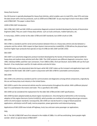
  • 9. • Based on electronic properties from the RS-485 bus. • Twisted pair wire with a maximum length of 40m. • The network is based on a bus topology. • Serial byte-oriented communication with least significant byte first. • Transmission rate 9600 bps. • A message contains of • a one byte long MID (Message Identification), • followed by a number of data bytes, • and finally a checksum. • A message can be up to 21 bytes long. • Error detection and handling at collision of message transmission. J1708 protocol uses the same transceiver as RS-485. The bus network supports at least 20 nodes with these transceivers. J1708 does not use the bus termination resistors used by RS-485. About SAE J1587 SAE J1708 makes up the physical and data link layers while SAE J1587 makes up the transport and application layers with respect to the OSI model. SAE J1587 is used in conjunction with SAE J1708 for automobile communication. J1587 is an automotive diagnostic protocol standard developed by the Society of Automotive Engineers (SAE) for heavy-duty and most medium-duty vehicles built after 1985. The J1587 protocol uses different diagnostic connectors. Up to 1995, individual OEMs used their own connectors. From 1996 to 2001, the 6-pin Deutsch-connector was standard. Beginning in 2001, most OEMs converted to the 9-pin Deutsch. Some OEMs still use the 6-pin Deutsch. It has mostly been used for US made vehicles, and also by Volvo. Other European brands have usually used KWP. Some quick facts: The J1587 protocol defines the format of J1708 messages sent between microprocessors devices in heavy duty vehicles. It also supports communication with external devices connected to the bus. • J1587 is an application layer and is used together with J1708, which is the physical layer. • J1587 describes a message format and defines parameters. • A J1587 message consists of MID, PID, data bytes and a checksum. • The length of a J1587 message is limited to 21 bytes according to J1708. • J1587 allows for sending messages longer than 21 bytes using a connection oriented transport service (COTS). J1708 Half-Duplex Collision Detection SAE J1708 is basically an RS485 hardware interface without the typical 120 ohm termination resistors. In typical applications, a half-duplex RS485 transceiver chip is used to connect to the bus. In order to avoid collisions, J1708 protocol rules dictate that the device must monitor the data bus while transmitting the first byte (MID) of its message. The questiojn is, how is this possible using a half-duplex transceiver? In other devices, half-duplex implied that receiving during transmission was not possible. Does the Receiver Output pin of the transceiver match the Driver Input during transmission? The answer to these question is that SAE J1708 uses RS-485 transceivers, but connects the serial transmit data to the enable line of the driver rather than to the data line. This means that the driver is effectively switching directions on every bit. This is similar to CANbus, in which one of the bit values is "dominant" and the other is "recessive". The logic of each node is supposed monitor the recessive bits of the MID byte to determine whether any other node is transmitting a dominant bit at that time. If it detects this condition, the other node has a higher-priority message, and this node should immediately drop out and retry its message later. So, connecting the UART transmit to the DE instead of the DI pin is the key as shown in the image below (picture borrowed from the SAE J1708 specs). sae-j1708-serial-data-bus-standard-node-diagram.jpg 9
  • 10. a-comprehensible-guide-to-j1939-by- wilfried-voss.jpg More Information on SAE J1708 and SAE J1587 • Introduction to SAE J1708 by Kvaser • Introduction to SAE J1587 by Kvaser • Texas Instrument Application Report On Automotive Physical Layer SAE J1708 A Comprehensible Guide to J1939 SAE J1939 has become the accepted industry standard and the vehicle network technology of choice for off-highway machines in applications such as construction, material handling, and forestry machines. J1939 is a higher-layer protocol based on Controller Area Network (CAN). It provides serial data communications between microprocessor systems (also called Electronic Control Units - ECU) in any kind of heavy duty vehicles. The messages exchanged between these units can be data such as vehicle road speed, torque control message from the transmission to the engine, oil temperature, and many more. The information in this book is based on two documents of the SAE J1939 Standards Collection: J1939/21 - Data Link Layer J1939/81 - Network Management A Comprehensible Guide to J1939 is the first work on J1939 besides the SAE J1939 standards collection. It provides profound information on the J1939 message format and network management combined with a high level of readability. => Read More... Sign up for our newsletter Name Name Email Email Submit Quick Links • About Us • CAN / SAE J1939 OEM Services • Documentation ◦ A Brief Introduction to Controller Area Network ◦ A Brief Introduction to SAE J1708 and J1587 ◦ A Brief Introduction to the SAE J1939 Protocol ◦ Controller Area Network (CAN) Prototyping With the ARM Cortex-M3 Processor • Blog • Shipping & Returns • RSS Syndication • Contact Us 10
  • 11. International Journal of Engineering Trends and Technology (IJETT) – Volume23 Number 5- May 2015 ISSN: 2231-5381 http://www.ijettjournal.org Page 237 Vehicle Automation Using J1708/J1587 Protocol with ECU Report, GPS and NFC Tanmoy Sarkar PG Student#1 , Dept Of ECE, PES College of Engineering, Mandya, Karnataka, India ABSTRACT The automobile industry, which in the past were highly dependent on the electro-mechanical subparts or modules have fully been revolutionized after the introduction of electronics. The electronic intervention involved various issues like working in compatibility with electro-mechanical modules, timing differences, wired losses, etc, but still held a edge over the basic electro-mechanical counterpart. Another issue was the communication scheming which needed to be fast and accurate for perfect balance between various integrated ECU's available in the vehicle. Keeping this point in view the Society of Automotive Engineers (SAE) built a protocol referred to as J1708/J1587 which is widely regarded as the most efficient wired framework ever existing for communication's between various ECU's. The SAE-J1708/J1587 has been used in the vehicle automation to obtain the parameter reports from the ECU as fast and as accurate as possible. The vehicle automation module also provides provision for GPS Transreceiver for obtaining the exact location of vehicle and thus is capable of tracking vehicle pathway. Another added advantage is the availability of NFC scheming that can reduce the user interventions driving the vehicle more and more towards complete automaticity. Keywords - ECU, SAE J1708/J1587, Vehicle Automation System, GPS, NFC INTRODUCTION The enormous growth in the prospects of achieving fast and uninterrupted or undaunted communication between the vehicle and the user are getting the automotive sector to a new era of dimension. The electronic revolution has undoubtedly taken over each and every aspect of life and has provided a base for the automotive industry to increase the overall safety and hardcoded luxury features which sometime people on dreamt about. Much recent history of automobile involves a lot more electronification than it was in the earlier days. The trend is with increasing count of modules per vehicle. Now days even in a generalized vehicle there exists an increasing numbers of ECU's with inter-linked communication strategies existing between each module. Communication between these modules makes the use of network protocols an essentially important factor. One such protocol is the SAE J1708/J1587 protocol. Considered to be a rather old standard but still plays a very important role when it comes to communication existing between modules of heavy loaded vehicles such as trucks and buses. It's being slow is overdone by its reliability and is used for secondary or less urgent data exchange. 11
  • 12. International Journal of Engineering Trends and Technology (IJETT) – Volume23 Number 5- May 2015 ISSN: 2231-5381 http://www.ijettjournal.org Page 238 Fig. 1 Block Diagram The Fig. 1 shows the whole of system architecture and the various communication interfaces the system is having. Through this one can have a idea of how exactly the system is taking the report from ECU and then providing it to the company server. WORKING PROCESS In Fig. 1 the middle figure is the basic automotive core that is serving as a small real time based embedded system. This is installed in the vehicle and communicate with the other components through various communication interface available depending whether the components can handle the communication interface and the data rates at which the information has to be transferred . The Automotive core consists of two microcontroller and several communication interfaces each providing some or the other feature. The first microcontroller is the ARM 7 based LPC series whereas the second controller is the ARM 9 based PNX series. The communication interface have the following:- I2C, SPI, UART, I2S, Timers, ADC, etc The Automotive core provides the user with underlined output data to be saved in the company server or cloud via the GPRS scheme as shown. The details that is provided as the output is the ECU reports as needed by the customer ,the GPS report (pre-mentioned details about the vehicle location and route follow) and the NFC based communication if the customer intended for the same. AQUIRING PARAMETER THROUGH SAE BUS The LPC series ARM 7 based microcontroller is embedded coded to obtain parameters values based on the protocol rules of the J1708/J1587 protocol through various sensors which itself serves as various nodes. The intention is that the protocol will promote a standard for serial communication between modules with microcontrollers The J1708 bus consists of two wires (A and B). The difference in voltage potential between wires determines the voltage level on the bus “A” and “B”. Logical high level (1) is achieved when point A is at least 200 mV more positive than point B. Logical low level (0) means that point A is at least 200 mV more negative than point B (See the following figure 2). The transceiver should be fed with +6V to -6V in relation to common ground. Fig. 2 Determination of bus logic level J1708 network uses a bus topology with “random” access to the bus. By Random access it is meant that any node has the capability to transmit whenever it requires unless the bus is not already busy. The bus must have been in idle mode (logical high level) for at least a bus access time before a node may access it. The time counting is based on the bit time which, at 9600 bps, is about 104.2 microseconds. Every message has a priority between 1 and 8, where 1 has highest priority. If two messages is sent at exactly the same time a collision occurs on the bus. When this happens both sending nodes have to release control of the bus. Both nodes then have to wait for a bus access time before they can start sending again. Consequently the node with highest priority will gain access to the bus first and can start to transmit its message. ECU Report ARM 7 LPC Series Controller ARM 9 PNX Series Controller NFC Module GPS Module SAE Protocol Bus Comm. Interfaces 2 Comm. Interfaces 1 GSM / GPRS Company Server 12
  • 13. International Journal of Engineering Trends and Technology (IJETT) – Volume23 Number 5- May 2015 ISSN: 2231-5381 http://www.ijettjournal.org Page 239 AQUIRING DATA THROUGH GPS RECEIVER Fig. 3 Vehicle Automation included with GPS Tracking At earth at least four GPS satellites are „visible‟ at any time from the individuals position . Each and every satellite transmits information about its current position and the current time at regular intervals depending upon the way the satellite has been time triggered. These signals which generally tend to travel at the speed of light, are intercepted by the GPS receiver, which calculates by various algorithms, how far away each satellite is based on how long it took for the messages to arrive. Once the receiver has the information on how far away at least three satellites are (a minimum of three satellite are imp. for accurate measurement), the GPS receiver can pinpoint at the current location using a process called trilateration. The concept in fig. 3 is to use the reading obtained by the GPS receiver and feed it to the ARM 9 based PNX series microcontroller. The microcontroller is coded to obtain GPS readings and it sends the location based data to the server using GPRS. AQUIRING DATA FOR NFC BASED EMBEDDED ELECTRONIC TOLL SYSTEM Fig. 4 NFC Embedded with Vehicle Automation System The concept utilized is that a NFC tag generally a passive one will be embedded to the Vehicle ARM 9 based PNX series microcontroller from one end while the other end in such a way that the tag will be directed under the number plate. Underground buried RF antennas will be there, once the vehicle approaches the range of the buried antennas it will trigger the NFC tag which will intend trigger the Vehicle automation system a message will be directed via GSM sim to receive and send Vehicle information. Once the information is verified completely the toll gates will open up. With the help of a counter each toll will also have the feature of counting the having the exact nos. of vehicles passing by it. SIMULATION RESULTS Totally 15 parameters are measured they are as follows A. Idle Time B. Return Speed Max C. Loading stop Time D. Loaded Travel Time E. Total Cycle Travel Distance F. Empty Travel Distance G. Return Speed Avg H. Load Tonne Satellite 2 GPS Module Satellite 1 GSM / GPRS PNX Series Microcontroller Satellite 4 Satellite 3 PNX Series NFC Tag at lower edge of Licence Plate Under Ground Buried Antenna Vehicle Information Centre GPRS Module Toll Information Centre 13
  • 14. International Journal of Engineering Trends and Technology (IJETT) – Volume23 Number 5- May 2015 ISSN: 2231-5381 http://www.ijettjournal.org Page 240 I. Haul Speed Max J. Total Cycle Travel Distance Time K. Empty Travel Time L. Loading Time M. Loaded Travel Distance N. Haul Speed Avg O. Check Sum All these 15 data‟s can be collected completely or specifically by selecting each and every parameter using the check box given along with the name of the parameters. The values can be retrieved within a specific amount of time or date. Fig. 5 GUI Page available to the user Simulations will be shown in the GUI to the user when above is filled Fig. 6 Data Obtained after Simulation Simulation for the GPS will be shown on GUI as Fig. 7 GPS Location traced during simulation CONCLUSION While Telematic have been an important part of the automotive industry for some time, the very latest techniques are set to become a standard element in all new cars. The Telematic in automobile industry are playing an important role by increasing the vehicle safety and by providing cosy rides. The latest systems combine GPS, cellular, advanced security, and in-car connectivity (e.g. the Controller Area Network, USB, and NFC). The most important application of this technology is the eCall automatic emergency system, which is triggered to automatically sends an electronic signal via the mobile network which includes both CDMA and GSM, to the emergency services in the event of an accident or any other mishappenings, providing location as well as other automobile component status More increase in Telematic results into the following, drivers will be pre warned about issues such as potential intersection collisions, nearby emergency braking, blind spot or lane-change issues, and "do not pass" warnings if existing. It also means that information regarding potential traffic congestion can be collected ahead of time with the available GPS service. The more latest technology is the evolvement of the Near Field Communication. NFC means that with just a tap of your Smartphone to your car key, you can use the phone to 14
  • 15. International Journal of Engineering Trends and Technology (IJETT) – Volume23 Number 5- May 2015 ISSN: 2231-5381 http://www.ijettjournal.org Page 241 monitor the status of your car including applications such as maintenance status, door lock status, car finder, etc. An automated car certainly has an exciting journey ahead of it. As more and more cars are able to evolve in terms of automation and Telematic the user can be provided with a suitable and cosy journey. REFERENCES (1) Real-Time Vehicle Tracking And Performance Monitoring Using Wireless Networking And The Internet :- William Jenkins, Ron Lew Is, Georgios Lazarou, Joseph Picone And Zachary Rowland (2) Near Field Communication (NFC) based Electronic Toll Collection System :- Nikhil Mohan , Savita Patil (3) Vehicle Detection And Tracking Techniques: A Concise Review :- Raad Ahmed Hadi, Ghazali Sulong and Loay Edwar George (4) Mobile and Ubiquitous Systems: Networking and Services :- Xue Yang Illinois Univ., Urbana, IL, USA Jie Liu ; Vaidya, N.F. ; Feng Zhao (5) LPC data sheet PNX data sheet by NXP Philips. (6) NXP Automotive documentary. AUTHOR PROFILE Tanmoy Sarkar is an M.Tech student in the Department of ECE in PESCE, Mandya affiliated by Visvesvaraya Technological University. His area of interest is Embedded Systems. 15
  • 16. Introduction to J1939 Version 1.1 2010-04-27 Application Note AN-ION-1-3100 Author(s) Markus Junger Restrictions Public Document Abstract This application note presents an overview of the fundamental concepts of J1939 in order to give a first impression. Table of Contents 1 Copyright © 2010 - Vector Informatik GmbH Contact Information: www.vector.com or ++49-711-80 670-0 1.0 Overview ..........................................................................................................................................................2 2.0 Parameter Groups ...........................................................................................................................................3 2.1 Interpretation of the CAN Identifier................................................................................................................3 2.2 Parameter Group Number.............................................................................................................................3 2.3 Suspect Parameter Number (SPN)...............................................................................................................4 2.4 Special Parameter Groups............................................................................................................................4 3.0 Network Management......................................................................................................................................5 3.1 Address Claiming Procedure ........................................................................................................................5 3.2 Request for Address Claim ...........................................................................................................................6 3.3 Address Capability ........................................................................................................................................7 4.0 Transport Protocols..........................................................................................................................................7 5.0 Diagnostics ......................................................................................................................................................9 6.0 Summary..........................................................................................................................................................9 7.0 Additional Sources.........................................................................................................................................10 8.0 Contacts.........................................................................................................................................................11 16
  • 17. Introduction to J1939 2 Application Note AN-ION-1-3100 1.0 Overview SAE J1939 is used in the commercial vehicle area for communication in the commercial vehicle. In this application note, the properties of SAE J1939 should be described in brief. SAE J1939 uses CAN (Controller Area Network, ISO11998) as physical layer. It is a recommended practice that defines which and how the data is communicated between the Electronic Control Units (ECU) within a vehicle network. Typical controllers are the Engine, Brake, Transmission, etc. Figure 1: Typical J1939 vehicle network The particular characteristics of J1939 are: • Extended CAN identifier (29 bit) • Bit rate 250 kbit/s • Peer-to-peer and broadcast communication • Transport protocols for up to 1785 data bytes • Network management • Definition of parameter groups for commercial vehicles and others • Manufacturer specific parameter groups are supported • Diagnostics features There exist several standards which are derived from SAE J1939. These standards use the basic features of SAE J1939 with a different set of parameter groups and modified physical layers. These standards are: ISO11783 – Tractors and machinery for agriculture and forestry – Serial control an communication Defines the communication between tractor and implements on an implement bus. It specifies some services on application layer, like Virtual Terminal, Tractor ECU, Task Controller and File Server. It adds an Extended Transport Protocol and Working Set Management. NMEA2000® – Serial-data networking of marine electronic devices It defines parameter groups for the communication between marine devices. It specifies the additional Fast Packet transport protocol. ISO11992 – Interchange of digital information between towing and towed vehicle Specifies the interchange of information between road vehicle and towed vehicle. It uses same parameter group format as J1939 on a different physical layer with 125 kbit/s. FMS – Fleet Management System The FMS standard defines a gateway between the J1939 vehicle network and a fleet management system. 17
  • 18. Introduction to J1939 3 Application Note AN-ION-1-3100 2.0 Parameter Groups A parameter group is a set of parameters belonging to the same topic and sharing the same transmission rate. The definition of the application relevant parameter groups and parameters can be found in application layer document [9]. The length of a parameter group is not limited to the length of a CAN frame. Usually a parameter group has a minimum length of 8 bytes up to 1785 bytes. Parameter groups with more than 8 bytes require a transport protocol for transmission. 2.1 Interpretation of the CAN Identifier The CAN identifier of a J1939 message contains Parameter Group Number (PGN), source address, priority, data page bit, extended data page bit and a target address (only for a peer-to-peer PG). The identifier is composed as follows: Priority Extended Data Page Data Page PDU Format PDU Specific Source Address 3 bit 1 bit 1 bit 8 bit 8 bit 8 bit • With PDU format < 240 (peer-to-peer), PDU specific contains the target address. Global (255) can also be used as target address. Then the parameter group is aimed at all devices. In this case, the PGN is formed only from PDU format. • With PDU format >= 240 (broadcast), PDU format together with the Group Extension in the PDU specific field forms the PGN of the transmitted parameter group. 2.2 Parameter Group Number Each parameter group is addressed via a unique number – the PGN. For the PGN a 24 bit value is used that is composed of the 6 bits set to 0, PDU Format (8 bits), PDU Specific (8 bits), Data Page (1 bit) and Extended Data Page (1 bit). There are two types of Parameter Group Numbers: • Global PGNs identify parameter groups that are sent to all (broadcast). Here the PDU Format, PDU Specific, Data Page and Extended Data Page are used for identification of the corresponding Parameter Group. On global PGNs the PDU Format is 240 or greater and the PDU Specific field is a Group Extension. • Specific PGNs are for parameter groups that are sent to particular devices (peer-to-peer). Here the PDU Format, Data Page and Extended Data Pare are used for identification of the corresponding Parameter Group. The PDU Format is 239 or less and the PDU Specific field is set to 0. 18
  • 19. Introduction to J1939 4 Application Note AN-ION-1-3100 With this breakdown of the PGN, 240 + (16 * 256) = 4336 different parameter groups within each data page are possible. With the transmission of a parameter group, the PGN is coded in the CAN identifier. With the Data Page bit and Extended Data Page bit 4 different data pages can be selected, see following table. Extended Data Page Bit Data Page Bit Description 0 0 SAE J1939 Page 0 Parameter Groups 0 1 SAE J1939 Page 1 Parameter Groups (NMEA2000 ® ) 1 0 SAE J1939 reserved 1 1 ISO 15765-3 defined Table 1: Data Pages Sample of a parameter group definition: Name: Engine temperature 1 – ET1 Transmission rate: 1s Data length: 8 bytes Extended Data Page 0 Data page: 0 PDU format: 254 PDU specific: 238 Default priority: 6 PG Number: 65,262 (00FEEE16) Description of data: Byte: 1 Engine Coolant Temperature 2 Engine Fuel Temperature 1 3,4 Engine Oil Temperature 1 5,6 Engine Turbocharger Oil Temperature 7 Engine Intercooler Temperature 8 Engine Intercooler Thermostat Opening 2.3 Suspect Parameter Number (SPN) A suspect parameter number is assigned to each parameter of a parameter group or component. It is used for diagnostic purpose to report and identify abnormal operation of a Controller Application (CA). The SPN is a 19 bit number and has a range from 0 to 524287. For proprietary parameters a range from 520192 to 524287 is reserved. 2.4 Special Parameter Groups SAE J1939-21 defines some parameter groups on the data link layer: Request parameter group The request parameter group (RQST, PGN 00EA0016) can be sent to all or a specific CA to request a specified parameter group. The RQST contains the PGN of the request parameter group. If the receiver of a specific request cannot respond, it must send a negative acknowledgment. The RQST has a data length code of 3 bytes and is the only parameter group with a data length code less than 8 bytes. Acknowledgement parameter group The acknowledgement parameter group (ACKM, PGN 00E80016) can be use to send a negative or positive acknowledgment, i.e. in response to a request. 19
  • 20. Introduction to J1939 5 Application Note AN-ION-1-3100 Address claiming parameter group The address claiming parameter group (ACL, PGN 00EE0016) is used for network management, see chapter 3.0. Commanded address parameter group The commanded address parameter group (CA, PGN 00FED816) can be used to change the address of a CA. Transport protocol parameter group The transport protocol parameter groups (TPCM, PGN 00EC0016 and TPDT, PGN 00EB0016) are used to transfer parameter groups with more than 8 data bytes, see chapter 4.0. 3.0 Network Management The software of an Electronic Control Unit (ECU) is the Controller Application (CA). An ECU may contain one or more CAs. Each CA has a unique address and an associated device name. Each message that is sent by a CA contains this source address. There are 255 possible addresses: • 0..253 – Valid source addresses for CAs • 0..127 and 248..253 – Used for CAs with Preferred Addresses and defined functions • 128..247 – Available for all CAs • 254 – Null • 255 – Global Most CAs like Engine, Gearbox, etc. have a preferred address (see [2]). Before a CA may use an address, it must register itself on the bus. This procedure is called "address claiming." Thereby the device sends an "Address Claim" parameter group (ACL, PGN 00EE0016) with the desired source address. This PG contains a 64-bit device name. If an address is already used by another CA, then the CA whose device name has the higher priority has claimed the address. The device name contains some information about the CA and describes its main function. A manufacturer code must be requested by the SAE. The values of the fields are defined in SAE J1939-81 [11]. Figure 2: Device name data of the address claim parameter group 3.1 Address Claiming Procedure In a common situation the controller application sends an Address Claim parameter group at start up and waits a defined amount of time. If it does not detect an address conflict it can start with its normal communication. 20
  • 21. Introduction to J1939 6 Application Note AN-ION-1-3100 Figure 3: Address claiming procedure In a situation where another CA already uses the address an address conflict occurs. The CA with the higher priority of the device name will obtain the address. The other CA must send a “Cannot Claim Address” parameter group, with source address Null (254). Figure 4: Address claiming procedure with address conflict It depends on the address capability of a CA how to proceed, if an address cannot be obtained. 3.2 Request for Address Claim A CA can detect other CAs in the network by requesting the ACL parameter group. It is allowed to use the Null- Address (254) as source address before a CA has performed the address claiming procedure. If the request is addressed to the Global address (255) all CAs in the network must respond with the ACL parameter group (including own CA if an address has been claimed already). 21
  • 22. Introduction to J1939 7 Application Note AN-ION-1-3100 Figure 5: Request address claim 3.3 Address Capability SAE J1939-81 defines the following types of capability to obtain an address: Arbitrary address capable CA The CA selects it source address by internal algorithm. It is able to select a new address on an address conflict. The Arbitrary Address Capable field in the device name indicates this capability. Single address capable CA A CA of this type can use only one address. On address conflicts it is not able to select another address. It can support the commanded address parameter group or proprietary mechanisms to change the address. The Arbitrary Address Capable field is not set for these CAs. 4.0 Transport Protocols Parameter groups that contain more than 8 data bytes are transmitted by means of a transport protocol. Figure 6: Transport Protocol For peer-to-peer and broadcast transmission, there are two different protocols. The transport protocols utilize two special parameter groups which are used for the connection management (TP.CM) and the transmission of the data (TP.DT). For broadcast transmission, the BAM (Broadcast Announce Message) protocol is used. Here, after a BAM-PG, the transmitter sends all data PGs at a minimum interval of 50ms. 22
  • 23. Introduction to J1939 8 Application Note AN-ION-1-3100 Figure 7: BAM transmission With the peer-to-peer transmission, the transmitter initiates the connection with a "request to send" message. The receiver then controls the transport protocol with "clear to send" and finally acknowledge it with "end of message acknowledge." Figure 8: RTS/CTS transmission 23
  • 24. Introduction to J1939 9 Application Note AN-ION-1-3100 5.0 Diagnostics The diagnostic features of SAE J1939 supports following services: • Reporting and identification of abnormal operation • Memory access • Monitored tests An important parameter group is the Diagnostics Message 1 (DM1, PGN FECA16). If supported, it shall be sent cyclic by each CA to report its state. The parameter group contains the state for different lamps: • Malfunction Indicator Lamp • Red Stop Lamp • Amber Warning Lamp • Protect Lamp An instrument cluster can use this information to report the state of the system to the driver. Additionally the parameter group contains a list of Diagnostic Trouble Codes (DTC). Together with the address of a sender the parameter of misbehaving components can be identified. Figure 9: Diagnostic Trouble Code A DTC contains 4 bytes, which contain the SPN, the Failure Mode Identifier (FMI) and an Occurrence Count. If the DM1 contains more than one DTC a transport protocol must be used. 6.0 Summary With the specification of the parameter groups, CAN identifier scheme, and the network management, a manufacturer-spanning cooperation of control units will be ensured. J1939 describes, in addition to the mechanisms presented here, the physical properties and use of bus sub segments. 24
  • 25. Introduction to J1939 10 Application Note AN-ION-1-3100 7.0 Additional Sources SAE Documents [1] SAE J1939 Recommended Practice for a Serial Control and Communications Vehicle Network [2] SAE J1939-01 Recommended Practice for Control and Communications Network for On-Highway Equipment [3] SAE J1939-02 Agricultural and Forestry Off-Road Machinery Control and Communication Network [4] SAE J1939-03 On Board Diagnostics Implementation Guide [5] SAE J1939-05 Marine Stern Drive and Inboard Spark-Ignition Engine On-Board Diagnostics Implementation Guide [6] SAE J1939-11 Physical Layer - 250k bits/s, Twisted Shielded Pair [7] SAE J1939-13 Off-Board Diagnostic Connector [8] SAE J1939-14 Physical Layer, 500k bits/s [9] SAE J1939-15 Reduced Physical Layer, 250K bits/sec, Un-Shielded Twisted Pair (UTP) [10] SAE J1939-21 Data Link Layer [11] SAE J1939-31 Network Layer [12] SAE J1939-71 Vehicle Application Layer [13] SAE J1939-73 Application Layer - Diagnostics [14] SAE J1939-74 Application - Configurable Messaging [15] SAE J1939-75 Application Layer - Generator Sets and Industrial [16] SAE J1939-81 Network Management [17] SAE J1939-82 Compliance - Truck and Bus [18] SAE J1939-84 OBD Communications Compliance Test Cases for Heavy Duty Components and Vehicles 25
  • 26. The J1939 Experts | Simma Software, Inc. J1587 SAE J1587 is a specification which defines messages that are transmitted on a SAE J1708 network. J1708 specifies the data link and physical layers, while J1587 specifies the transport, network, and application layers. J1587 is similar to J1922, which also defines messages for a J1708 network and also the same three protocol layers. J1587 is outdated and being replaced by J1939. J1587 Purpose The purpose of SAE J1587 is to define the format of the messages and data being communicated between microprocessors used in heavy-duty vehicle applications. It is meant to serve as a guide toward a standard practice to promote software compatibility among microcomputer based modules. J1587 is to be used with SAE J1708, which defines the requirements for the hardware and basic protocol that is needed to implement J1587. J1587 Messages J1587 uses messages for diagnostic purposes. For example, it sends messages for fuel economy, coolant temperature, fault codes (also known as diagnostic trouble codes or DTCs) and many other parameters. All together J1587 defines around 500 parameters. J1587 does not send control type messages, instead that is handled by J1922. J1587 Message Format All messages have the following format: Message ID One or More Parameters Checksum Messages start with a MID, which stands for message identifier and indicates the source address of the transmitting node. For examples, see the below MID table. The next value is the PID, which stands for parameter identifier and indicates what parameter the following data corresponds to. The data and its length are defined by the PID value. After the corresponding data, either another PID is present or the message is terminated with a checksum. MID, PID/Data, [PID/Data, PID/Data, ...], Checksum 26
  • 27. The J1939 Experts | Simma Software, Inc. J1587 MID Example Table 0-127 Defined by SAE J1708 128 Engine #1 129 Turbocharger 130 Transmission 131 Power Takeoff 132 Axle, Power Unit 133 Axle, Trailer #1 134 Axle, Trailer #2 135 Axle, Trailer #3 136 Brakes, Power Unit 137 Brakes, Trailer #1 138 Brakes, Trailer #2 139 Brakes, Trailer #3 140 Instrument Cluster …… 242 Axles, Trailer #4 243 Axles, Trailer #5 244 Diagnostic Systems, Trailer #4 245 Diagnostic Systems, Trailer #5 246 Brakes, Trailer #4 247 Brakes, Trailer #5 248 Forward Road Image Processor 249 Body Controller 250 Steering Column Unit 251-255 Reserved to be assigned J1587 Parameter Length The amount of data which is transmitting following a PID is defined by the value of the PID. A PID of 0 to 127 is followed by a single byte of data. PIDs from 128 to 191 are followed by two bytes of data and PIDs greater than or equal to 192 are variable length. 27
  • 28. The J1939 Experts | Simma Software, Inc. J1587 PID Example Table 0 Request Parameter 1 Invalid Data Parameter 2 Transmitter System Status 3 Transmitter System Diagnostic 4 Reserved 5 Underrange Warning Condition 6 Overrange Warning Condition 7 Axle #2 Lift Air Pressure 8 Brake System Air Pressure Low Warning Switch Status 9 Axle Lift Status 10 Axle Slider Status 11 Cargo Securement 12 Brake Stroke Status 13 Entry Assist Position/Deployment 14 Entry Assist Motor Current 15 Fuel Supply Pump Inlet Pressure 16 Suction Side Fuel Filter Differential Pressure 17 Engine Oil Level Remote Reservoir 18 Extended Range Fuel Pressure 19 Extended Range Engine Oil Pressure 20 Extended Range Engine Coolant Pressure … 128 Component-specific request 129 Injector Metering Rail #2 Pressure 130 Power Specific Fuel Economy 131 Exhaust Back Pressure 132 Mass Air Flow 133 Average Fuel Rate 134 Wheel Speed Sensor Status J1587 Priority In J1587, priority is assigned to individual parameters. However, J1587 is transmitted by J1708 which contains a single priority for each message. If multiple J1587 parameters are packed into a single message, the message shall take on the priority of the highest priority parameters. Priorities have a range of 1 to 8 and specify how much extra time has to be waited before the message can be transmitted once the J1708 network goes idle. Therefore, priorities influence the amount of network bandwidth available. 28
  • 29. The J1939 Experts | Simma Software, Inc. J1587 Example For example, J1587 specifies a parameter for engine speed. The 'Engine Speed', which is PID 190, defines the parameter to be an unsigned 16-bit value, with a bit resolution of 0.25 RPM/bit, offset of 0 RPMs, and a network update period of 100 ms. Below are two more examples. PID 183 Fuel Rate (Instantaneous)—Amount of fuel consumed by engine per unit of time. Parameter Data Length: 2 Characters Data Type: Unsigned Integer Bit Resolution: 16.428 x 10 6 L/s (4.34 x 10 6 gal/s or 1/64 gal/h) Maximum Range: 0.0 to 1.076 65 L/s (0.0 to 0.284 421 90 gal/s or 0.0 to 1023.98 gal/h) Transmission Update Period: 0.2 s Message Priority: 3 Format: PID Data 183 aa a a— Fuel Rate (instantaneous) PID 184 Instantaneous Fuel Economy—Current fuel economy at current vehicle velocity. Parameter Data Length: 2 Characters Data Type: Unsigned Integer Bit Resolution: 1.660 72 x 10 3 km/L (1/256 mpg) Maximum Range: 0.0 to 108.835 km/L (0.0 to 255.996 mpg) Transmission Update Period: 0.2 s Message Priority: 3 Format: PID Data 184 aa a a— Instantaneous fuel economy 29
  • 30. The J1939 Experts | Simma Software, Inc. J1587 Diagnostics J1587 sends diagnostic information very similar to the J1939 DTC approach. J1587 uses PID 194, which is titled ‘Transmitter System Diagnostic Code and Occurrence Count Table’, to report diagnostic information. When there is an active fault, PID 194 is transmitted periodically and is always available by request. The PID 194 message contains the SID/PID identifier of the failure and the FMI. J1587 SID Subsystem Identification Numbers (SIDs) are numbers assigned by the SAE or the SAE Truck and Bus Low Speed Communications Network Subcommittee. There are 255 SIDs definable for each controller or MID. SIDs are numbers that can be used to identify a section of a control system without a related PID. SIDs should only be assigned to field-repairable or replaceable subsystems for which failures can be detected and isolated by the controller (MID). SIDs 1 to 150 are assigned by SAE staff. SIDs 156 to 255 are assigned by the SAE Truck and Bus Low Speed Communications Network Subcommittee. MID related SIDs start with number 1 and sequentially increase. Common SIDs start at 254 and sequentially decrease. Below is an example of engine related SIDs. Engine SIDs (MID = 128, 175, 183, 184, 185, 186) 0 Reserved 1 Injector Cylinder #1 2 Injector Cylinder #2 3 Injector Cylinder #3 4 Injector Cylinder #4 5 Injector Cylinder #5 6 Injector Cylinder #6 7 Injector Cylinder #7 8 Injector Cylinder #8 9 Injector Cylinder #9 10 Injector Cylinder #10 11 Injector Cylinder #11 12 Injector Cylinder #12 13 Injector Cylinder #13 14 Injector Cylinder #14 15 Injector Cylinder #15 16 Injector Cylinder #16 17 Fuel Shutoff Valve 18 Fuel Control Valve 19 Throttle Bypass Valve 20 Timing Actuator 21 Engine Position Sensor 22 Timing Sensor 23 Rack Actuator 24 Rack Position Sensor 30
  • 31. The J1939 Experts | Simma Software, Inc. J1587 FMI The Failure Mode Identifier, FMI, describes the type of failure detected in the subsystem identified by the PID or SID. The FMI, and either the PID or SID combine to form a given diagnostic code. If additional common failure modes become detectable, the remaining failure mode identifiers would be assigned by the SAE Truck and Bus Low Speed Communications Network Subcommittee. J1587 FMI Table 0 Data valid but above normal operational range (that is, engine overheating) 1 Data valid but below normal operational range (that is, engine oil pressure too low) 2 Data erratic, intermittent, or incorrect 3 Voltage above normal or shorted high 4 Voltage below normal or shorted low 5 Current below normal or open circuit 6 Current above normal or grounded circuit 7 Mechanical system not responding properly 8 Abnormal frequency, pulse width, or period 9 Abnormal update rate 10 Abnormal rate of change 11 Failure mode not identifiable 12 Bad intelligent device or component 13 Out of Calibration 14 Special Instructions 15 Reserved for future assignment by the SAE Subcommittee 31
  • 32. Home Documentation A Brief Introduction to SAE J1708 and J1587 Call us on 413-475-3651 or SAE J1708 is a standard used for serial communications between ECUs on a heavy duty vehicle and also between a computer and the vehicle. With respect to Open System Interconnection model (OSI), J1708 defines the physical layer. Common higher layer protocols that operate on top of J1708 are SAE J1587 and SAE J1922. The protocol is maintained by SAE International. The standard defines a 2-wire 18 gauge wire cable that can run up to 130 feet (40 m) and operates at 9600 bit/s. A message is composed of up to 21 characters, unless the engine is stopped and the vehicle is not moving in which case transmitters are allowed to exceed the 21 byte max message length. Messages start with a Message ID (MID) character and finish with a checksum at the end. My Account Gift Certificates Wish Lists Sign in Create an account Search A Brief Introduction to SAE J1708 and J1587 http://copperhilltech.com/a-brief-introduction-to-sae-j1708-and-j1587/ 1 of 5 02/04/2017 12:10 a.m. 32
  • 33. Characters are transmitted in the common 8N1 format. The hardware utilized are RS-485 transceivers wired for open collector operation through the use of a pullup and pulldown of the separate data lines. Transmission is accomplished by controlling the driver enable pin of the transceiver. This method allows multiple devices to share the bus without the need for a single master node. Collisions are avoided by monitoring the bus while transmitting the MID to ensure that another node has not simultaneously transmitted a MID with a higher priority. SAE J1708, although still widely used, is replaced by SAE J1939 which is a CAN (Controller Area Network) based protocol. Some quick facts: Describes the physical and data link layer according to OSI model. Almost always used in conjunction with the application layer protocol SAE J1587. Based on electronic properties from the RS-485 bus. Twisted pair wire with a maximum length of 40m. The network is based on a bus topology. Serial byte-oriented communication with least significant byte first. Transmission rate 9600 bps. A message contains of a one byte long MID (Message Identification), followed by a number of data bytes, and finally a checksum. A message can be up to 21 bytes long. Error detection and handling at collision of message transmission. J1708 protocol uses the same transceiver as RS-485. The bus network supports at least 20 nodes with these transceivers. J1708 does not use the bus termination resistors used by RS-485. SAE J1708 makes up the physical and data link layers while SAE J1587 makes up the transport and application layers with respect to the OSI model. SAE J1587 is used in conjunction with SAE J1708 for automobile communication. J1587 is an automotive diagnostic protocol standard developed by the Society of Automotive Engineers (SAE) for heavy-duty and most medium-duty vehicles built after 1985. The J1587 protocol uses different diagnostic connectors. Up to 1995, individual OEMs used their own connectors. From 1996 to 2001, the 6-pin Deutsch-connector was standard. Beginning in 2001, most OEMs converted to the 9-pin Deutsch. Some OEMs still use the 6-pin Deutsch. It has mostly been used for US made vehicles, and also by Volvo. Other European brands have usually used KWP. Some quick facts: The J1587 protocol defines the format of J1708 messages sent between microprocessors devices in A Brief Introduction to SAE J1708 and J1587 http://copperhilltech.com/a-brief-introduction-to-sae-j1708-and-j1587/ 2 of 5 02/04/2017 12:10 a.m. 33
  • 34. heavy duty vehicles. It also supports communication with external devices connected to the bus. J1587 is an application layer and is used together with J1708, which is the physical layer. J1587 describes a message format and defines parameters. A J1587 message consists of MID, PID, data bytes and a checksum. The length of a J1587 message is limited to 21 bytes according to J1708. J1587 allows for sending messages longer than 21 bytes using a connection oriented transport service (COTS). SAE J1708 is basically an RS485 hardware interface without the typical 120 ohm termination resistors. In typical applications, a half-duplex RS485 transceiver chip is used to connect to the bus. In order to avoid collisions, J1708 protocol rules dictate that the device must monitor the data bus while transmitting the first byte (MID) of its message. The questiojn is, how is this possible using a half-duplex transceiver? In other devices, half-duplex implied that receiving during transmission was not possible. Does the Receiver Output pin of the transceiver match the Driver Input during transmission? The answer to these question is that SAE J1708 uses RS-485 transceivers, but connects the serial transmit data to the enable line of the driver rather than to the data line. This means that the driver is effectively switching directions on every bit. This is similar to CANbus, in which one of the bit values is "dominant" and the other is "recessive". The logic of each node is supposed monitor the recessive bits of the MID byte to determine whether any other node is transmitting a dominant bit at that time. If it detects this condition, the other node has a higher-priority message, and this node should immediately drop out and retry its message later. So, connecting the UART transmit to the DE instead of the DI pin is the key as shown in the image below (picture borrowed from the SAE J1708 specs). A Brief Introduction to SAE J1708 and J1587 http://copperhilltech.com/a-brief-introduction-to-sae-j1708-and-j1587/ 3 of 5 02/04/2017 12:10 a.m. 34
  • 35. Introduction to SAE J1708 by Kvaser Introduction to SAE J1587 by Kvaser Texas Instrument Application Report On Automotive Physical Layer SAE J1708 SAE J1939 has become the accepted industry standard and the vehicle network technology of choice for off-highway machines in applications such as construction, material handling, and forestry machines. J1939 is a higher-layer protocol based on Controller Area Network (CAN). It provides serial data communications between microprocessor systems (also called Electronic Control Units - ECU) in any kind of heavy duty vehicles. The messages exchanged between these units can be data such as vehicle road speed, torque control message from the transmission to the engine, oil temperature, and many more. The information in this book is based on two documents of the SAE J1939 Standards Collection: J1939/21 - Data Link Layer J1939/81 - Network Management A Comprehensible Guide to J1939 is the first work on J1939 besides the SAE J1939 standards collection. It provides profound information on the J1939 message format and network management combined with a high level of readability. => Read More... Name Email A Brief Introduction to SAE J1708 and J1587 http://copperhilltech.com/a-brief-introduction-to-sae-j1708-and-j1587/ 4 of 5 02/04/2017 12:10 a.m. 35
  • 36. 1 The SAE J1939 Communications Network An overview of the J1939 family of standards and how they are used Since its publication more than a decade ago, SAE J1939 has become widely accepted as the Controller Area Network (CAN) for on-highway trucks, off-highway equipment, agricultural equipment, construction equipment, and other vehicles. What is J1939? From the Foreword to J1939 (Serial Control and Communications Heavy Duty Vehicle Network)... “The SAE J1939 communications network is a high speed ISO 11898-1 CAN-based communications network that supports real-time closed loop control functions, simple information exchanges, and diagnostic data exchanges between Electronic Control Units (ECUs), physically distributed throughout the vehicle. The SAE J1939 common communication architecture strives to offer an open interconnect system that allows ECUs associated with different component manufacturers to communicate with each other.” J1939 covers the design and use of devices that transmit electronic signals and control information among vehicle components. Used as an application layer, J1939 provides communication between the engine control, transmission control, vehicle body control, and other applicable sub-control systems. J1939 also defines message timeouts, how large messages are fragmented and reassembled, the network speed, the physical layer, and how applications acquire network addresses. The J1939 communications network is defined using a collection of individual SAE J1939 documents based upon the layers of the Open System Interconnect (OSI) model for computer communications architecture. An SAE White Paper 36
  • 37. 2 A “Family” of Documents The J1939 standards “family” consists of the top level document (J1939 itself) and 16 companion documents. J1939 is the master control for definitions common to many applications. This document provides the comprehensive list of all assigned data parameter and diagnostic identifiers (SPNs), all assigned messages (PGNs), and all assignments for NAME and Address identifiers. The top level document serves as the central registry for these assignments even though the technical details for most SPNs and PGNs are specified throughout the other documents in the J1939 family. The top level document describes the network in general, the OSI layering structure, and the subordinate document structure, as well as providing control for all preassigned values and names. J1939 is: • Developed for use in heavy-duty environments • Suitable for horizontally-integrated vehicle industries The physical layer aspects of SAE J1939 reflect its design goal for use in heavy-duty environments. But the J1939 communications network is applicable for light-duty, medium-duty, and heavy-duty vehicles used on-road or off-road, and appropriate stationary applications which use vehicle-derived components (such as generator sets). The companion documents explain component rationalization and product standardization for a particular application or industry. Specific documents in the J1939 family describe the recommended practices for networks in: • Heavy-Duty On-Highway Vehicles • Agricultural and Forestry Off-Road Machinery • Marine Stern Drive and Inboard Spark-Ignition Engines Companion documents also describe layers used in the OSI network architecture, such as: • Physical Layer • Data Link Layer • Network Layer • Vehicle Application Layer J1939 Compliance There is no procedure presently in place to test, validate or provide formal approval for ECUs utilizing the SAE J1939 network. Developers are expected to design their products in the spirit of, as well as the specific content of, the recommended practice. In the future, procedures may be defined for the testing of products to ensure compliance. Until then, compliance is determined by the manufacturer of the component. J1939 gives OEMs the ability for customized communication. 37
  • 38. 3 J1939 Benefits Because a vehicle’s electronic systems are connected to one central network, vehicle monitoring and management is enhanced. Vehicle systems become more serviceable because they are all connected to one network. Thus, J1939 results in improvements in: • Vehicle flexibility and reliability • Product standardization • Parts economy • Self-diagnostics • Log and record capabilities • Calibration of individual components • Reading or deleting the diagnostics data of individual components • Transmitting measurement values and control data to configure components History The J1939 family of standards is developed by SAE’s Truck and Bus Control and Communications Network Committee, which reports to the Electrical and Electronics Steering Committee of the Truck and Bus Council. Participants in the Control and Communications Network Committee include personnel from OEMs, suppliers, consulting firms, governmental agencies, and others involved in the truck and bus industry. The top-level document, J1939, was originally published in April 2000. It has since been revised in 2003, 2005, 2007, 2009, 2010, and most recently, in April 2011. As stated in the original publication of J1939, the purpose of the recommended practices was to “provide an open interconnect system for electronic systems. It is the intention of these recommended practices to allow Electronic Control Units to communicate with each other by providing a standard architecture.” The J1939 network was the next generation successor to the SAE J1708 and SAE J1587 low speed networks. Those earlier standards provided simple information exchange, including diagnostic data, between ECUs. J1939 was capable of performing all of the functions of those earlier networks. It enhanced previous capabilities and added new ones to better support controls and multiplexing on a single network. The J1939 Standards Collection on the Web The most convenient and comprehensive way to access everything related to the SAE J1939 family of standards is through the SAE J1939 Standards Collection on the Web. This web-based subscription service provides access to the top level document (J1939), as well as the 16 core companion documents. Whenever any of these documents is revised, or if a new standard is added, the subscription is updated automatically. In addition, the subscription includes more than 20 related standards and technical papers, and the Companion Spreadsheet for 1939, a supplementary Excel document consisting of the parameters and parameter groups contained in J1939 standards. Single user, one-year subscription: $650 To order, or for more information: sae.org/j1939 1-888-875-3976 CustomerSales@sae.org 38
  • 39. 4 Technology had advanced to the point where a high speed communication network was feasible. It was needed to secure higher bandwidth capabilities for more demanding control needs, so that component suppliers could integrate subsystems for improved performance, and to meet customer expectations and government regulations. A number of documents in the J1939 family preceded the publication of the top level document. For example, these recommended practices were available in 1994: • J1939-11: Physical Layer, 250K bits/s, Twisted Shielded Pair • J1939-21: Data Link Layer • J1939-31: Network Layer Revision, expansion and updating of all standards in the J1939 family is ongoing. The following four documents in the J1939 family have been revised in 2011: • J1939-01: Recommended Practice for Control and Communications Network for On-Highway Equipment • J1939-71: Vehicle Applications Layer • J1939-75: Application Layer – General Sets and Industrial • J1939-81: Network Management J1939 and CAN J1939 uses the CAN protocol which permits any ECU to transmit a message on the network when the bus is idle. Every message uses an identifier that defines: • The message priority • From whom it was sent • The data that is contained within it Collisions are resolved non-destructively as a result of the arbitration process that occurs while the identifier is transmitted. I D E S O F 1 Identifier 11 R T R 1 1 DLC 4 Data Field 0 - 64 ACK Field 2Bits CRC Delimiter 1 r 0 1 CRC 15 7 EOF Bit Stuffing No Bit Stuffing CAN Data Frame Maximum frame length with bit stuffing = 127 bits Data Field Control Field 6 Bits Arbitration Field 12 Bits A. CAN Standard Frame Format B. CAN Extended Frame Format S O F 1 Identifier 11 S R R 1 I D E 1 DLC 4 Data Field 0 - 64 ACK Field 2Bits CRC Delimiter 1 Arbitration Field 32 Bits r 0 1 Control Field 6 Bits Data Field CRC 15 7 E O F Bit Stuffing CAN Extended Data Frame Maximum frame length with bit stuffing = 150 bits r 1 1 Identifier Ext. R T R 118 No Bit Stuffing 39
  • 40. 5 This permits high priority messages to get through with low latency (delay) times because there is equal access on the network for any ECU. When multiple ECUs are simultaneously attempting to transmit, the highest priority message prevails. This results in maximum reliability, combined with maximum possible performance, leading to better vehicle performance, and reduced production costs. CAN systems enable use of a single command station to control diagnostic systems and receive information such as: • Brake and transmission temperature • Tire pressure • Fuel efficiency • Emission levels J1939 uses the 29-Bit identifier to identify the source, and in some cases, the destination of data on the bus. J1939 extends the use of the 29-Bit CAN identifier beyond the standard CAN message identification. J1939 takes advantage of these features of CAN: • Reduced wiring (CAN requires only two wires between nodes) • Reliable communication • Easy implementation • Improved maintenance and service capabilities • Error detection and fault confinement • Collision-free bus arbitration J1939 Applications in Industry J1939 has been widely adopted by diesel engine manufacturers and in the commercial vehicle sector. J1939 is heavily used in the following vehicle applications: • Diesel powertrain applications • In-vehicle networks for trucks and buses • Agricultural machinery • Forestry machinery • Truck-trailer connections • Mining equipment • Military vehicles • Fleet management systems • Recreational vehicles • Marine navigation systems J1939 has been used as the basis for the development of other industry-specific standards, including ISO 11783 for agricultural machinery, MilCAN for military applications, and NMEA 2000 for marine applications. Recently, six major European truck manufacturers developed the FMS (Fleet Management System), a common standard for trucks based on J1939. Companies using J1939 include Volvo, MACK, John Deere, Caterpillar, Nissan Diesel, and Navistar. mplement Bridge Hitch Management Compouter Gateway Farm Management Information System Implement Bus GPS VT Task Controller Implement ECU EngineHitch Tractor Bus Implement Sub Network Implement ECU Management Computer Interface Implement Bridge Tractor ECU 40
  • 41. 6 J1939-01 On-Highway Equipment Control and Communications Network This document was updated in May 2011 to more accurately describe the J1939 network as typically used in heavy duty on-highway vehicle applications. J1939-02 Agricultural and Forestry Off-Road Machinery Control and Communications Network This document is intended to specify the requirements for application of J1939 in construction and agricultural equipment. This document specifies the series of documents within the set of J1939 documents that are applicable to construction and agricultural equipment and provides further requirements for this industry. J1939-03 On-Board Diagnostics Implementation Guide This document provides requirements and guidelines for the implementation of On-Board Diagnostics (OBD) on heavy-duty vehicles (HDV) using the SAE J1939 family of standards. The guidelines identify where the necessary information to meet OBD regulations may be found among the SAE J1939 document set. Key requirements are identified to insure the interoperability of OBD scan tools across individual OBD compliant vehicles. J1939-05 Marine Stern Drive and Inboard Spark-Ignition Engine On-Board Diagnostics Implementation Guide This document describes the application of the SAE J1939 recommended practices for compliance with on-board diagnostic malfunction detection system requirements for marine stern drive and inboard spark ignition engines, as mandated by the California Air Resources Board. J1939-11 Physical Layer – 250k bits/s, Twisted Shielded Pair The physical layer is a realization of an electrical connection of a number of ECUs to a network. The total number of ECUs will be limited by electrical loads on the bus line. This document defines a physical median of shielded twisted pair. J1939-13 Off-Board Diagnostics Connector This document describes the off-board diagnostic connector used on the vehicle to get access to the vehicle communication links. J1939-15 Reduced Physical Layer, 250K bits/sec, Unshielded Twisted Pair (UTP) This document describes a physical layer utilizing Unshielded Twisted Pair (UTP) cable. J1939-21 Data Link Layer This document describes the data link layer using the CAN protocol with 29-bit identifiers. For SAE J1939 no alternative data link layers are permitted. J1939-31 Network Layer This document describes the Network Layer which defines the requirements and services needed for the electronic devices (Network Interconnection ECUs) providing intercommunications between different segments of the SAE J1939 Vehicle Network. It also defines the various types of Network Interconnection ECUs and the functions they provide. J1939-71 Vehicle Application Layer This recommended practice describes an Application Layer for vehicle use. The J1939 Family of Standards In addition to J1939 (Recommended Practice for a Serial Control and Communications Vehicle Network), the J1939 family of documents consists of: 41
  • 42. 7 SAE International (commonly referred to as SAE) is a global association of more than 128,000 engineers and related technical experts in the aerospace, automotive, and commercial-vehicle industries. SAE International’s core competencies are life-long learning and voluntary consensus standards development. SAE International’s charitable arm is the SAE Foundation, which supports many programs, including A World In Motion® and the Collegiate Design Series. For more information on SAE, please visit www.sae.org. J1939-73 Application Layer – Diagnostics This document identifies the diagnostic connector to be used for the vehicle service tool interface and defines messages to accomplish diagnostic services. California-regulated OBD II requirements are satisfied with a subset of the specified connector and the defined messages. Diagnostic messages (DMs) provide the utility needed when the vehicle is being repaired. Diagnostic messages are also used during vehicle operation by the networked electronic control modules to allow them to report diagnostic information and self-compensate as appropriate, based on information received. Diagnostic messages include services such as periodically broadcasting active diagnostic trouble codes, identifying operator diagnostic lamp status, reading or clearing diagnostic trouble codes, reading or writing control module memory, providing a security function, stopping/ starting message broadcasts, reporting diagnostic readiness, and monitoring engine parametric data. J1939-74 Application – Configurable Messaging This document describes the message structure for a set of messages that enable the user to determine and announce to others on the network, the parameter placement within a particular message from the special set of messages defined within this document. J1939-75 Application Layer – Generator Sets and Industrial This document defines the set of data parameters (SPNs) and messages (PGNs) for information predominantly associated with monitoring and control generators and driven equipment in electric power generation and industrial applications. J1939-81 Network Management Network management in the SAE J1939 network is concerned with the management of source addresses and the association of those addresses with an actual function and with the detection and reporting of network related errors. Due to the nature of management of source addresses, network management also specifies initialization processes, requirements for reaction to brief power outages and minimum requirements for ECUs on the network. J1939-82 Compliance – Truck and Bus The purpose of these compliance procedures is to generate one or more test documents that outline the tests needed to assure that an ECU that is designed to operate as a node on an SAE J1939 network would do so correctly. These tests are presented to allow testing of a device to determine self-compliance by the manufacturer. The manufacturer can use its record of what procedures were run successfully to show the level of compliance with SAE J1939. J1939-84 OBD Communications Compliance Test Cases for Heavy Duty Components and Vehicles The purpose of this recommended practice is to verify that vehicles and/or components are capable of communicating a required set of information, in accordance with the diagnostic test messages specified in SAE J1939-73, to fulfill the off-board diagnostic tool interface requirements contained in government regulations. This document describes the tests, test methods, and results for verifying diagnostics communication from an off board diagnostic tool (i.e., scan tool) to a vehicle and/ or component. This document serves as a guide for testing vehicles for compliance with ARB and other requirements for emissions-related on-board diagnostic (OBD) functions for heavy duty engines used in medium and heavy duty vehicles. 42
  • 43. 43
  • 44. 44
  • 45. 45
  • 46. 46
  • 47. 47
  • 48. 48
  • 49. 49
  • 50. Store Categories OBD1 + OBD2 Scanner OBDII Auto Scanner VAG Auto Scanner Auto Scanner for BMW Bluetooth Scanner WIFI Auto Scanner Auto Scanner for Trucks & Excavators Others Products Professional C68 Auto Scanner Auto Scanner for MANY Trucks & Excavators Auto Scanner for MANY BMW Cars Shipping Payment Contact us Return & Exchange Feedback Auto Scanner For Heavy Truck & Excavator J1708 J1939 Item Description This auto scanner is for Heavy Truck & Excavator specially. It has integrated the basic diagnostic functions of two heavy duty truck standard protocols (J1939 and J1708), applied 2.8" color LCD with nice interface, and equipped with 6 PIN and 9 PIN additional diagnostic connectors, which can provide highest quality, most efficient, and most professional diagnostic service for heavy duty trucks. From now on, the heavy duty trucks also have their own small-scale diagnostic tool. Detailed Functions : 1.Read fault code 2.Clear fault code 3.Read data streams 4.Support multiple ECUs 5.Support 6PIN, 9PIN, and 16PIN diagnostic connectors For different trucks,the definition of the connectors maybe not the same. The jump wires maybe needed even if your truck's connector is 6 pin or 9 pin. When you use jump wires,you need to know the definition of the connector of your truck. 6.Support J1939, and J1708 vehicle communication protocols 7.For J1708,it support: engine, gearbox, dashboard, particles, transmission, brakes, suspension, ABS, vehicle stability system, electronic power systems, fuel systems 8.Products with diagnostics memory function, the user's real-time diagnostic data can be stored in the EEPROM inside, you can also copy data via USB interface to a computer for analysis. Product Parameters : Screen: 2.8", 262K true color, 320*240 LCD Input voltage range: 8 36V Operating current: typically <100mA Typical power consumption: <1.2W Wire connection: 6PIN, 9PIN, 16PIN diagnostic connector Environmental temperature: 0 50 Storage temperature and humidity: -20 70 @ RH 60% External dimension: L*W*H=121*82*26mm Single unit: <500g Packing list: Main Unit (with 16 pin connecotr) ×1 6 PIN Connector×1 9 PIN Connector×1 USB cable for update×1 Nylon Carry Bag×1 Jump wire×4 1 All items will be shipped within 24 business hours upon receipt of payment Creator OBD2 OBDii Auto Scanner Code Reader 66.55 USD Buy It Now Free shipping Universal OBD2 OBDii Scanner Code Reader 62.55 USD Buy It Now Free shipping OBD2 OBDii Scanner Fault Code Reader Automotive 66.66 USD Buy It Now Free shipping OBD2 OBDii Scanner Fault Code Reader Diagnostic Tool 66.95 USD Buy It Now Free shipping Universal OBD2 OBDii Scanner Fault Code Reader 69.99 USD Buy It Now Free shipping OBD2 OBDii Auto Scanner Read & Clear Fault Codes for 55.99 USD Buy It Now Free shipping Auto Scan tool For Diesel Heavy Truck &amp; Excavator HD Auto S... http://www.ebay.com/itm/Auto-Scan-tool-For-Diesel-Heavy-Truck-Ex... 2 of 3 01/04/2017 11:44 p.m. 50
  • 51. 51
  • 55. 1 Introduction Introduction How To Use This Manual 2 Use MID and your model/brand to find Fault Code Chart page number PgMID 128 - Engine CAT . . . . . . . . . . . . . . . . . . . . . . .2 Cummins . . . . . . . . . . . . . . . . . . .3 Detroit Diesel . . . . . . . . . . . . . . . .8 International . . . . . . . . . . . . . . . .12 Mack . . . . . . . . . . . . . . . . . . . . .16 MID 130 - Transmission Eaton AC-AS1 . . . . . . . . . . . . . . .17 Eaton AS2-ASX . . . . . . . . . . . . .18 Eaton ASW . . . . . . . . . . . . . . . . .19 Eaton CEEMAT . . . . . . . . . . . . . .20 Eaton CEMT . . . . . . . . . . . . . . . .21 Eaton DM2 . . . . . . . . . . . . . . . . .22 Eaton Lightning . . . . . . . . . . . . .23 Meritor FreedomLin . . . . . . . . . .24 Meritor SureShift . . . . . . . . . . . .25 MID 136 - Brakes (ABS) Bendix Tractor ABS . . . . . . . . . .26 Eaton Tractor ABS . . . . . . . . . . .29 Wabco Pneumatic Tractor ABS .32 Wabco Hydraulic ABS . . . . . . . .34 MID 137 - Trailer (ABS) Bendix Trailer ABS . . . . . . . . . . .35 Eaton Trailer ABS . . . . . . . . . . . .37 Haldex Trailer ABS . . . . . . . . . . .39 Wabco Trailer ABS . . . . . . . . . . .41 MID 142 - Engine Mack . . . . . . . . . . . . . . . . . . . . .42 MID 158 - Engine Mack . . . . . . . . . . . . . . . . . . . . .42 MID 219 - VORAD Eaton VORAD . . . . . . . . . . . . . . .43 3 Use PID/SID and FMI numbers to locate the Fault Code MID 128 - CAT PID/SID - 110 FMI - 003 Fault Code - 27 PID/ SID FMI 105 4 38 Intake Manifold Air Temperature Sensor Short Circuit 11 64 Very High Intake Manifold Air Temp 108 3 26 Atmospheric Pressure Sensor Open Circuit 4 26 Atmospheric Pressure Sensor Short Circuit 110 0 61 High Coolant Temperature Warning 3 27 Coolant Temp Sensor Open Circuit 4 27 Coolant Temp Sensor Short Circuit 11 61 Very High Coolant Temperature 111 1 62 Low Coolant Level Warning Fault Code Fault Description Sample Fault Code Chart Sample Display 128 PID/SID FMIMID 110 003 Identifies module or ECU Identifies data or status Describes type of failure 1 Plug in tool and read display See possible connectors on page 44 55
  • 56. 2 MID 128 - CAT MID 128 - CAT CAT PID/ SID FMI Fault Code Fault Description 1 11 72 Cylinder 1 Fault 2 11 72 Cylinder 2 Fault 3 11 73 Cylinder 3 Fault 4 11 73 Cylinder 4 Fault 5 11 74 Cylinder 5 Fault 6 11 74 Cylinder 6 Fault 22 13 42 Check Timing Sensor Calibration 30 8 29 Invalid PTO Throttle Signal 13 29 PTO Throttle Sensor Calibration 41 3 21 Volt Supply Above Normal 4 21 Volt Supply Below Normal 71 0 1 Idle Shutdown Override 1 47 Idle Shutdown Occurrence 84 0 41 Vehicle Over speed Warning 1 31 Loss of Vehicle Speed Signal 2 36 Invalid Vehicle Speed Signal 8 36 Vehicle Speed Out of Range 10 36 Vehicle Speed Rate of Change 91 8 32 Invalid Throttle Signal 13 28 Throttle Sensor Calibration 100 1 46 Low Oil Pressure Warning 3 24 Oil Pressure Sensor Open Circuit 4 24 Oil Pressure Sensor Short Circuit 11 46 Very Low Oil Pressure 102 0 25 Boost Pressure Sensor Stuck High 3 25 Boost Pressure Sensor Open Circuit 4 25 Boost Pressure Sensor Short Circuit 13 42 Boost Pressure Sensor Calibration 105 0 64 High Intake Manifold Air Temp. Sensor Open Circuit 3 38 Intake Manifold Air Temp. Sensor Open Circuit 105 4 38 Intake Manifold Air Temp. Sensor Short Circuit 11 64 Very High Intake Manifold Air Temp 108 3 26 Atmospheric Press. Sensor Open Circuit 4 26 Atmospheric Press. Sensor Short Circuit 110 0 61 High Coolant Temperature Warning 3 27 Coolant Temp Sensor Open Circuit 4 27 Coolant Temp Sensor Short Circuit 11 61 Very High Coolant Temperature 111 1 62 Low Coolant Level Warning 2 12 Coolant Level Sensor Fault 11 62 Very Low Coolant Level 121 5 14 Retarder Solenoid Lo/Hi Open Circuit 6 14 Retarder Solenoid Lo/Hi Short Circuit 122 5 14 Retarder Solenoid Med/Hi Open Circuit 6 14 Retarder Solenoid Med/Hi Short Circuit 168 2 51 Low/Intermittent Battery Power to ECM 174 0 65 High Fuel Temperature Warning 3 13 Fuel Temperature Sensor Open Circuit 4 13 Fuel Temperature Sensor Short Circuit 190 0 35 Engine Over speed Warning 2 34 Loss of Engine RPM Signal 228 3 19 A/C High Pressure Switch Open Circuit 231 11 58 J1939 Data Link Fault 232 3 21 Volt Supply Above Normal 4 21 Volt Supply Below Normal 244 2 2 Event Recorder Data Lost 249 11 58 Power train Data Link Fault 252 11 59 Incorrect Engine Software 12 59 Personality Module Fault 253 2 56 Check Customer or System Parameters 254 12 53 ECM Fault CAT (Continued) PID/ SID FMI Fault Code Fault Description 56
  • 57. 3 MID 128 - Cummins MID128-Engine MID 128 - Cummins Cummins PID/ SID FMI Fault Code Fault Description 1 6 311 Cylinder 1 Fault 322 Cylinder 1 Fault 7 1139 Injector Cylinder #1 2 6 315 Cylinder 2 Fault 331 Cylinder 2 Fault 7 1141 Injector Cylinder #2 3 6 313 Cylinder 3 Fault 324 Cylinder 3 Fault 7 1142 Injector Cylinder #3 4 6 321 Cylinder 4 Fault 332 Cylinder 4 Fault 7 1143 Injector Cylinder #4 5 6 312 Cylinder 5 Fault 323 Cylinder 5 Fault 7 1144 Injector Cylinder #5 6 6 314 Cylinder 6 Fault 325 Cylinder 6 Fault 7 1145 Injector Cylinder #6 9 11 768 Output Device Driver 15 1 583 Fuel Supply Pump Inlet Pressure Sensor 3 581 Fuel Supply Pump Inlet Pressure Sensor 4 582 Fuel Supply Pump Inlet Pressure Sensor 17 1 219 Low Oil Level 2 472 Engine Oil Level #2 473 Engine Oil Level #2 4 254 Low Voltage Detected on Fuel Shutoff Solenoid 7 259 Fuel Shutoff Valve 11 391 Fuel Shutoff Valve 18 2 468 Fuel Rail Actuator Circuit 3 276 Fuel Injection Control Valve 455 Fuel Control Valve Circuit 18 4 279 Fuel Injection Control Valve 5 378 Fueling Actuator #1 6 379 Fueling Actuator #1 7 277 Fuel Injection Control Valve 514 Fuel Control Valve Circuit 11 539 Injector Control Valve Electronic Filter 2311 Fuel Control Valve #1 13 493 Fuel Pump Calibration Trim Circuit Error 19 0 349 Transmission Output Shaft Speed 20 2 467 Timing Rail Actuator Circuit 3 113 Engine Timing Actuator 4 114 Engine Timing Actuator 5 394 Timing Actuator #1 6 395 Timing Actuator #1 7 112 Engine Timing Actuator 11 2312 Timing Actuator #1 22 0 555 Engine Blow by - Warning Level 3 719 Crankcase Pressure Sensor 4 729 Crankcase Pressure Sensor 23 6 172 Rack Position Sensor 7 173 Rack Actuator 24 3 166 Rack Position Sensor 25 14 599 OEM Commanded Dual Output Shut- down 26 3 255 Externally Supplied Voltage at of the fol- lowing: Fuel Shutoff Valve, Fan Clutch, Engine Brake 27 0 9122 Variable Geometry Turbocharger 2 957 EGR Position Sensor Circuit 1228 EGR Position Sensor Circuit 3 2271 EGR Valve Position Sensor Circuit 2277 Variable Geometry Turbocharger Actua- tor #1 Cummins (Continued) PID/ SID FMI Fault Code Fault Description 57
  • 58. 4 MID 128 - Cummins 27 3 2385 Variable Geometry Turbocharger 27 4 2272 EGR Valve Position Sensor Circuit 2278 Variable Geometry Turbocharger Actua- tor #1 2384 Variable Geometry Turbocharger 5 2383 Variable Geometry Turbocharger 6 2386 Variable Geometry Turbocharger 7 2387 Variable Geometry Turbocharger 13 2348 EGR Valve Position 2388 Variable Geometry Turbocharger 29 2 288 SAE J1939 Data Link Remote Throttle Data 3 133 Remote Accelerator Pedal Position Sen- sor 133 Remote Accelerator Pedal Position Sen- sor 4 134 Remote Accelerator Pedal Position Sen- sor 134 Remote Accelerator Pedal Position Sen- sor 30 2 237 External Speed Input 32 4 466 Turbocharger #1 Wastgate Control Cir- cuit 33 3 2181 Fan Clutch Output Device Driver 2377 Fan Clutch Output Device Driver 4 245 Clutch Fan Low Voltage 11 389 Fan Clutch Circuit Error 39 3 584 Starter Relay Circuit 4 585 Starter Relay Circuit 40 3 527 Auxiliary Input/Output #2 51 3 529 Auxiliary Input/Output #3 11 779 Auxiliary Equipment Sensor Input #3 14 2195 Auxiliary Equipment Sensor Input #3 57 3 2557 Auxiliary PWM Driver #1 4 2558 Auxiliary PWM Driver #1 Cummins (Continued) PID/ SID FMI Fault Code Fault Description 64 2 753 Engine Speed/Position #2 778 Engine Speed Sensor #2 2322 Engine Speed Sensor #2 7 731 Engine Speed Sensor #2 70 3 2555 Inlet Air Heater Driver #1 4 2556 Inlet Air Heater Driver #1 73 11 278 Fuel Priming Pump 78 3 316 Fuel Supply Pump Actuator 7 318 Fuel Supply Pump Actuator 83 5 396 Fueling Actuator #2 6 397 Fueling Actuator #2 84 2 241 Loss of Vehicle Speed Signal 5 398 Timing Actuator #2 6 399 Timing Actuator #2 12 242 Invalid Vehicle Speed Signal 85 4 223 Engine Oil Burn Valve Solenoid 86 4 225 Engine Oil Burn Valve Solenoid 91 2 287 SAE J1939 Data Link Remote Accelera- tor Pedal 431 No Voltage Detected at Idle Validation Switch 551 Voltage Detected simultaneously at Idle Validation Switch 3 131 High Voltage detected at Throttle Sensor 515 Accelerator Pedal Position Sensor 4 132 Low Voltage detected at Throttle Sensor 516 Accelerator Pedal Position Sensor 8 147 Accelerator Pedal Position Sensor 148 Accelerator Pedal Position Sensor 13 432 Voltage Detected at Idle Validation Switch 93 2 528 OEM Alternate Torque Validation Switch 94 0 449 Fuel Pressure High 2216 Fuel Pump Deliver Pressure Cummins (Continued) PID/ SID FMI Fault Code Fault Description 58
  • 59. 5 MID 128 - Cummins MID128-Engine 94 1 482 Fuel Pressure Low 2215 Fuel Pump Deliver Pressure 2 268 Fuel Pressure Sensor 3 546 Fuel Delivery Pressure Sensor 4 547 Fuel Delivery Pressure Sensor 95 0 2372 Fuel Filter Restriction Moderately High - Warning 97 0 418 Water in Fuel Indicator 3 428 Water in Fuel Indicator 4 429 Water in Fuel Indicator 98 1 253 Engine Oil Level 471 Engine Oil Level Low 2 252 Engine Oil Level 100 1 143 Low Oil Pressure 415 Low Oil Pressure Warning 2 435 Engine Oil Pressure Sensor 3 135 High Voltage detected at Oil Pressure Sensor 4 141 Low Voltage detected at Oil Pressure Sensor 102 2 433 High Boost Pressure 2973 Boost Pressure 3 122 High Voltage Detected at Boost Pressure Sensor 4 123 Low Voltage Detected at Boost Pressure Sensor 103 0 595 Turbocharger #1 High Speed 595 Turbocharger Speed #1 1 687 Turbocharger Speed #1 10 2345 Turbocharger Speed Invalid 105 0 155 Intake Manifold Air Temperature Above 200 Deg. F 488 Intake Manifold Air Temperature High 2964 Intake Manifold #1 Temp Cummins (Continued) PID/ SID FMI Fault Code Fault Description 105 3 153 High Voltage Detected at Intake Mani- fold Air Temperature Sensor 4 154 Low Voltage Detected at Intake Manifold Air Temperature Sensor 108 2 295 Ambient Air Pressure Sensor 3 221 Atmospheric Pressure Sensor 4 222 Atmospheric Pressure Sensor 109 1 233 Engine Coolant Pressure Sensor 3 231 Engine Coolant Pressure Sensor 4 232 Engine Coolant Pressure Sensor 110 0 151 Coolant Temperature Above 220 Deg F 1119 Engine Coolant Temp 2963 Engine Coolant Temp High 3 144 High Voltage Detected at Coolant Tem- perature Sensor 4 145 Low Voltage Detected at Coolant Tem- perature Sensor 111 1 197 Coolant Level 235 Low Coolant Level Warning 2 422 Very Low Coolant Level 3 195 Coolant Level 4 196 Coolant Level 112 0 1236 Water Pump Delta P 1 1233 Water Pump Delta P 1234 Water Pump Delta P 2 1235 Water Pump Delta P 3 1231 Water Pump Delta P 4 1232 Water Pump Delta P 113 2 524 OEM Alternate Droop Switch 114 2 497 Multiple Unit Synchronization Switch Circuit 117 11 299 Engine Shut Down Commanded by J1939 121 4 243 Retarder Solenoid Low Voltage 126 3 272 High Fuel Pressure Solenoid Valve #1 Cummins (Continued) PID/ SID FMI Fault Code Fault Description 59