
Recommended
More Related Content
Similar to Marine Centre Plymouth
Similar to Marine Centre Plymouth (20)
More from rgaskill
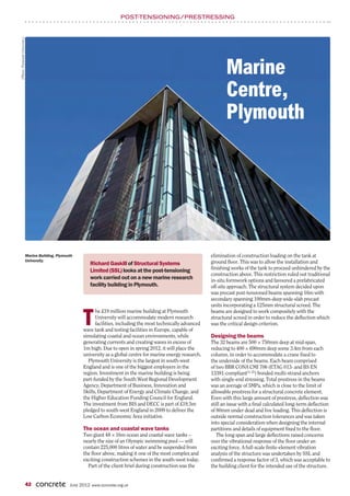
Marine Centre Plymouth
- 1. POST-TENSIONING/PRESTRESSING (Photo: Plymouth University.) Marine Centre, Plymouth Marine Building, Plymouth elimination of construction loading on the tank at University. ground floor. This was to allow the installation and Richard Gaskill of Structural Systems Limited (SSL) looks at the post-tensioning finishing works of the tank to proceed unhindered by the construction above. This restriction ruled out traditional work carried out on a new marine research in-situ formwork options and favoured a prefabricated facility building in Plymouth. off-site approach. The structural system decided upon was precast post-tensioned beams spanning 16m with secondary spanning 100mm-deep wide-slab precast units incorporating a 125mm structural screed. The he £19 million marine building at Plymouth beams are designed to work compositely with the T University will accommodate modern research facilities, including the most technically advanced wave tank and testing facilities in Europe, capable of structural screed in order to reduce the deflection which was the critical design criterion. simulating coastal and ocean environments, while Designing the beams generating currents and creating waves in excess of The 32 beams are 500 × 750mm deep at mid-span, 1m high. Due to open in spring 2012, it will place the reducing to 400 × 690mm deep some 3.4m from each university as a global centre for marine energy research. column, in order to accommodate a crane fixed to Plymouth University is the largest in south-west the underside of the beams. Each beam comprised England and is one of the biggest employers in the of two BBR CONA CMI 706 (ETAG 013- and BS EN region. Investment in the marine building is being 13391-compliant(1–2)) bonded multi-strand anchors part-funded by the South West Regional Development with single-end stressing. Total prestress in the beams Agency, Department of Business, Innovation and was an average of 5MPa, which is close to the limit of Skills, Department of Energy and Climate Change, and allowable prestress for a structural concrete element. the Higher Education Funding Council for England. Even with this large amount of prestress, deflection was The investment from BIS and DECC is part of £19.5m still an issue with a final calculated long-term deflection pledged to south-west England in 2009 to deliver the of 80mm under dead and live loading. This deflection is Low Carbon Economic Area initiative. outside normal construction tolerances and was taken into special consideration when designing the internal The ocean and coastal wave tanks partitions and details of equipment fixed to the floor. Two giant 48 × 16m ocean and coastal wave tanks – The long span and large deflections raised concerns nearly the size of an Olympic swimming pool –– will over the vibrational response of the floor under an contain 225,000 litres of water and be suspended from exciting force. A full-scale finite-element vibration the floor above, making it one of the most complex and analysis of the structure was undertaken by SSL and exciting construction schemes in the south-west today. confirmed a response factor of 3, which was acceptable to Part of the client brief during construction was the the building client for the intended use of the structure. 42 concrete JUNE 2012 www.concrete.org.uk
- 2. POST-TENSIONING/PRESTRESSING Right: Design development CAD images of one of the 16m-span precast post- tensioned beams. ❝ Lifting under the beam self weight. Under full-load stress, The beam reinforcement was fixed in a yard off-site reversal took place and the tensile stresses in the bottom and cast in a custom-made steel mould. Using steel as of the beam took on their maximum value. The beams the formwork ensured a consistent finish to all beams, The on-site column reinforcement was fitted with weighed 13 tonnes resulting in an aesthetically pleasing concrete. The couplers at the underside level of the beam in order to and were some beam was then lifted out of the mould and allowed to receive H32 continuity reinforcement bars threaded of the largest cure. through 6 × 60mm vertical ducts formed in the enlarged precast beams to Once the concrete reached the required design hammer head end section of the beam. A fitting strength the beam was stressed using a multi-strand tolerance of 11mm horizontally was required in order be used in building jack and stored in the yard until required on-site. to achieve coupling of the column reinforcement. This construction in Transporting the 16.3m beams to site was a logistical is less than the typical construction allowance and was the UK. ❞ feat in itself and required a specialised trailer and a large achieved by paying close attention to the short-term crane on-site to lift the beams into position. The beams shrinkage characteristics of the prestressed concrete weighed 13 tonnes and were some of the largest precast and fixing reinforcement in the yard and on-site to very beams to be used in building construction in the UK. In tight tolerances. order to lift and place them onto the columns over the Once the beams were lifted into place the underside 50m building length a special high-load-capacity crane of the beam was grouted to achieve a uniform bearing was imported from Asia. surface. The bars were threaded and secured to the couplers and finally the ducts were grouted to secure the beam permanently in position. Supporting the beams Supporting the beams on a relatively small column width meant that the traditional recess provided for the multi-strand anchor interfered with the anchorage length for the support reinforcement. Placing the anchor-bearing plate on the external face of the beam removed the recess requirement but left the anchor exposed. The architect accepted the detail once a plastic end cap was sourced to minimise the impact of the protrusion on the building space. SSL (UK) also undertook the in-situ prestressing of two beams providing support for one of the suspended coastal tanks. The beams were 800 wide × 1000mm deep and carried the 300-tonne tank over a 16m span. These beams were cast in-situ at mezzanine level using traditional formwork construction. Use of two BBR CONA CMI 706 multi-strand anchors for each beam eliminated three layers of congested bottom reinforcement and provided a crack-free structure, increasing the durability and design life of the tank. ● Above: The beam Design of the beam had to consider the different reinforcement and post- tensioning was fixed and permutations involved in the lifting process. The initial installed in an off-site lift out of the mould occurred without the prestress References concrete precast yard. applied so it was crucial that sufficient reinforcement was provided to enable this lift to occur without 1. EUROPEAN ORGANISATION FOR TECHNICAL APPROVALS, ETAG damaging the beam. During the lifting process for 013. Guideline for European Technical Approval of Post-Tensioning Kits for Prestressing of Structures. EOTA, Brussels, 2002. transport to site the tensile stress in the top of the beam 2. BRITISH STANDARDS INSTITUTION, BS EN 13391. Mechanical was at its maximum due to the combined beam prestress tests for post-tensioning systems. BSI, London, 2004. and the moment arising from the lifting point locations 44 concrete JUNE 2012 www.concrete.org.uk