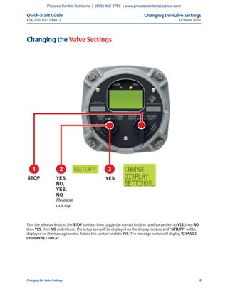
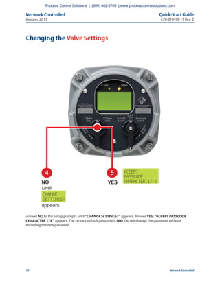
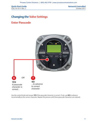
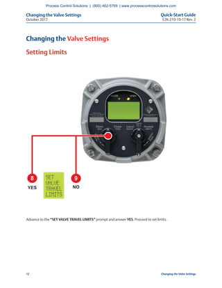
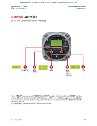
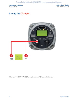
The quick-start guide provides instructions for setting up and configuring an EIM TEC2 electric actuator with a model 500. It describes how to power on the actuator, set the initial position limits for electrical or manual operation, check the open and closed settings, change valve settings like display configuration, and set the network address if using network control. The guide walks through each step using images and text to ensure the actuator is ready for normal operation.
An introduction to Semiconductor and its types.pptx
EIM TEC2 Electric Actuator with Model 500 Quick-Start Guide
1. Quick-Start Guide
E2K-210-10-17 Rev. 2
October 2017
EIM TEC2 Electric Actuator with
Model 500 Quick-Start Guide
Process Control Solutions | (800) 462-5769 | www.processcontrolsolutions.com
3. Welcome to TEC2
October 2017
Quick-Start Guide
E2K-210-10-17 Rev. 2
1Welcome to TEC2
Welcome to TEC2
The TEC2 actuator’s Local Display Module (LDM) and Remote Display Module (RDM) provide easy-to-read
actuator information.
The screen graphics will display the mode of operation, valve status, position, torque, and alarm symbols.
The message center will display actuator setup options, data entry feedback, and alarm messages.
Once you follow the simple steps outlined in this guide, the actuator will be ready for normal operation.
The bar graph, position digits, icons, and LEDs will indicate the valve status.
LED Indicators
Valve Torque
Display Diagnostic
Operation
Module
Moving Status
Process Control Solutions | (800) 462-5769 | www.processcontrolsolutions.com
4. Welcome to TEC2 Quick-Start Guide
E2K-210-10-17 Rev. 2October 2017
2 Welcome to TEC2
Factory Settings
The actuator has been configured as specified in the order. No further changes should be necessary other than
setting the position limits, and, if network controlled, setting a unique network address. If full data was not
provided when ordering or if changes are needed, see the TEC2 Installation & Operation Manual
(E2K-420-0117), which can be found at www.emerson/eim.
Power Actuator
Verify the voltage rating on the unit nameplate. Connect power to the unit.
Are Position Limits Set?
Does “SET LIMITS BEFORE OPERATING,” “EE%,” and the alarm icon appear, and is the yellow LED
blinking? If so, then position limits have not been set.
Process Control Solutions | (800) 462-5769 | www.processcontrolsolutions.com
5. Setting Valve Position Limits Initially
October 2017
Quick-Start Guide
E2K-210-10-17 Rev. 2
3Setting Valve Position Limits Initially
Setting Valve Position Limits Initially
2 3 4
YES LOCALYES,
NO,
YES,
NO
Release
quickly.
1
STOP
Place the selector knob in the STOP position. Then toggle the control knob in rapid succession to YES, then
NO, then YES, then NO and release. The Setup icon will be displayed on the display module and “SETUP?” will
be displayed on the message center. Rotate the control knob to “YES.” The message center will display “SET
LIMITS BEFORE OPERATING.” Set position limits as described on the next pages.
Process Control Solutions | (800) 462-5769 | www.processcontrolsolutions.com
6. Setting Position Limits for Electrical Operation Quick-Start Guide
E2K-210-10-17 Rev. 2October 2017
4 Setting Position Limits for Electrical Operation
Setting Position Limits for Electrical Operation
STEP 1: CLOSED Valve Position
2 3 4
YESLOCAL CLOSE
Hold until
desired
position is
reached.
1
STOP
Turn the selector knob to the LOCAL position. At the “CLOSE VALVE THEN SELECT STOP” prompt, hold the
control knob in the CLOSE position until the desired position is reached. Return the selector knob to the STOP
position. At the “ACCEPT CLOSE LIMIT” prompt, select “YES.”
Process Control Solutions | (800) 462-5769 | www.processcontrolsolutions.com
7. Setting Position Limits for Electrical Operation
October 2017
Quick-Start Guide
E2K-210-10-17 Rev. 2
5Setting Position Limits for Electrical Operation
Setting Position Limits for Electrical Operation
STEP 2: OPEN Valve Position
Turn the selector knob to the LOCAL position. At the “OPEN VALVE THEN SELECT STOP” prompt, hold the
control knob in the OPEN position until the desired position is reached. Return the selector knob to the STOP
position. At the “SAVE LIMITS” prompt, select “YES.” Rotate selector knob to either next or back until “EXIT”
is displayed, then select “YES.”
2 3 4
YESLOCAL OPEN
Hold until
desired
position is
reached.
1
STOP
Process Control Solutions | (800) 462-5769 | www.processcontrolsolutions.com
8. Setting Position Limits for Manual Operation Quick-Start Guide
E2K-210-10-17 Rev. 2October 2017
6 Setting Position Limits for Manual Operation
Setting Position Limits for Manual Operation
STEP 1: CLOSED Valve Position
Turn the selector knob to the LOCAL position. At the “CLOSE VALVE THEN SELECT STOP” prompt, depress the
declutch lever while rotating the handwheel until the clutch is fully engaged. Release the lever.
When the valve is fully closed, move the valve in the open direction for one handwheel turn to allow for
coasting of the motor. Return the selector knob to the STOP position. At the “ACCEPT CLOSE LIMIT” prompt,
select “YES.”
Advance to the “SAVE CHANGES?” prompt and answer YES to save the changes.
2 3 4
YESLOCAL
1
STOP
5
Depress
declutch,
rotate
handwheel
until...
declutch is fully
engaged.
Release
declutch,
rotate toward
open for 1 turn.
Process Control Solutions | (800) 462-5769 | www.processcontrolsolutions.com
9. Setting Position Limits for Manual Operation
October 2017
Quick-Start Guide
E2K-210-10-17 Rev. 2
7Setting Position Limits for Manual Operation
Setting Position Limits for Manual Operation
STEP 2: OPEN Valve Position
Turn the selector knob to the LOCAL position. At the “OPEN VALVE THEN SELECT STOP” prompt, depress the
declutch lever while rotating the handwheel until the clutch is fully engaged. Release the lever.
When the valve is fully opened, move the valve in the close direction for one handwheel turn to allow for
coasting of the motor. Return the selector knob to the STOP position. At the “SAVE LIMITS” prompt,
select “YES.”
Advance to the “SAVE CHANGES?” prompt and answer YES to save the changes.
2 3 4
YESLOCAL
1
STOP
5
Depress
declutch,
rotate
handwheel
until...
declutch is fully
engaged.
Release
declutch,
rotate toward
open for 1 turn.
Process Control Solutions | (800) 462-5769 | www.processcontrolsolutions.com
10. Check the Open/Closed Settings Quick-Start Guide
E2K-210-10-17 Rev. 2October 2017
8 Check the Open/Closed Settings
Check the Open/Closed Settings
Valve Closed
As you operate the valve in the close direction, verify
that the green LED is blinking. When fully closed is
reached, verify that the green LED stays ON and 0%
is displayed.
1 When turning to close,
green LED blinks.
2 When fully closed,
green LED remains lit.
Valve Open
As you operate the valve in the open direction, verify
that the red LED is blinking. When fully open is
reached, verify that the red LED stays ON and 100%
is displayed.
1 When turning to
open, red LED blinks.
2 When fully open,
red LED remains lit.
Note
It is also configurable to have a red LED for
Valve Closed.
Note
It is also configurable to have a green LED for
Valve Open.
Process Control Solutions | (800) 462-5769 | www.processcontrolsolutions.com
11. Changing the Valve Settings
October 2017
Quick-Start Guide
E2K-210-10-17 Rev. 2
9Changing the Valve Settings
Changing the Valve Settings
Turn the selector knob to the STOP position then toggle the control knob in rapid succession to YES, then NO,
then YES, then NO and release. The setup icon will be displayed on the display module and “SETUP?“ will be
displayed on the message center. Rotate the control knob to YES. The message center will display “CHANGE
DISPLAY SETTINGS”.
2 3
YESYES,
NO,
YES,
NO
Release
quickly.
1
STOP
Process Control Solutions | (800) 462-5769 | www.processcontrolsolutions.com
12. Network Controlled Quick-Start Guide
E2K-210-10-17 Rev. 2October 2017
10 Network Controlled
Changing the Valve Settings
Answer NO to the Setup prompts until “CHANGE SETTINGS?” appears. Answer YES. “ACCEPT PASSCODE
CHARACTER 1?X” appears. The factory default passcode is 000. Do not change the password without
recording the new password.
4 5
YESNO
Until
appears.
Process Control Solutions | (800) 462-5769 | www.processcontrolsolutions.com
13. Network Controlled
October 2017
Quick-Start Guide
E2K-210-10-17 Rev. 2
11Network Controlled
Changing the Valve Settings
Enter Passcode
Use the control knob and answer YES if the passcode character is correct. If not, use NO to advance
incrementally to the correct character. Repeat this process until three passcode characters are entered.
6 7
YES NO
If passcode
character is
correct...
...to advance
to correct
character.
OR
Process Control Solutions | (800) 462-5769 | www.processcontrolsolutions.com
14. Changing the Valve Settings Quick-Start Guide
E2K-210-10-17 Rev. 2October 2017
12 Changing the Valve Settings
Changing the Valve Settings
Setting Limits
Advance to the “SET VALVE TRAVEL LIMITS” prompt and answer YES. Proceed to set limits.
8 9
YES NO
Process Control Solutions | (800) 462-5769 | www.processcontrolsolutions.com
15. Network Controlled
October 2017
Quick-Start Guide
E2K-210-10-17 Rev. 2
13Network Controlled
Network Controlled
(CAM and Controlinc®
option required)
In the “SETUP” mode advance to “NETWORK SETUP?” using the selector knob in the REMOTE position.
Answer YES. Hold the control knob in the NO position until the correct address appears. Answer YES. Unit
is now network controlled. If other configuration changes are needed, please see the TEC2 Installation &
Operation Manual
(E2K-420-0117), which can be found at www.emerson/eim.
2 3 4
YESNO
Until...
1
REMOTE
5
NO
Until
correct
address...
YES
Process Control Solutions | (800) 462-5769 | www.processcontrolsolutions.com
16. Saving the Changes Quick-Start Guide
E2K-210-10-17 Rev. 2October 2017
14 Saving the Changes
Saving the Changes
Advance to the “SAVE CHANGES?” prompt and answer YES to save the changes.
1 2
YES NOCHANGES?
Process Control Solutions | (800) 462-5769 | www.processcontrolsolutions.com