
Recommended
Recommended
More Related Content
Similar to Caterpillar Cat D6T XW TRACK-TYPE TRACTOR (Prefix TMY) Service Repair Manual Instant Download.pdf
Similar to Caterpillar Cat D6T XW TRACK-TYPE TRACTOR (Prefix TMY) Service Repair Manual Instant Download.pdf (14)
More from onyvzcwadtu05
More from onyvzcwadtu05 (20)
Recently uploaded
Recently uploaded (20)
Caterpillar Cat D6T XW TRACK-TYPE TRACTOR (Prefix TMY) Service Repair Manual Instant Download.pdf
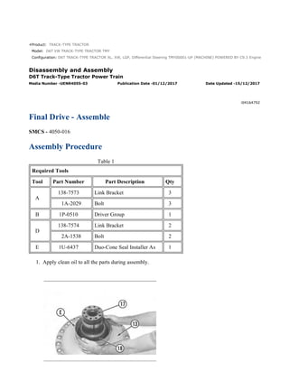
- 1. Product: TRACK-TYPE TRACTOR Model: D6T XW TRACK-TYPE TRACTOR TMY Configuration: D6T TRACK-TYPE TRACTOR XL, XW, LGP, Differential Steering TMY00001-UP (MACHINE) POWERED BY C9.3 Engine Disassembly and Assembly D6T Track-Type Tractor Power Train Media Number -UENR4055-03 Publication Date -01/12/2017 Date Updated -15/12/2017 i04164792 Final Drive - Assemble SMCS - 4050-016 Assembly Procedure Table 1 Required Tools Tool Part Number Part Description Qty A 138-7573 Link Bracket 3 1A-2029 Bolt 3 B 1P-0510 Driver Group 1 D 138-7574 Link Bracket 2 2A-1538 Bolt 2 E 1U-6437 Duo-Cone Seal Installer As 1 1. Apply clean oil to all the parts during assembly. 1/6 D6T TRACK-TYPE TRACTOR XL, XW, LGP, Differential Steering TMY00001-UP ... 2021/8/29 https://127.0.0.1/sisweb/sisweb/techdoc/techdoc_print_page.jsp?returnurl=/sis...
- 2. Illustration 1 g00841209 2. Use Tooling (B) to install lip seal (17) in spindle (13) to a minimum depth of 9.65 mm (0.4 inch). Do not apply excessive force to lip seal (17) during installation in order to avoid damaging the seal. Put clean oil on the lip of the seal. 3. Raise the temperature of bearing cone (18) to a maximum temperature of 135 °C (275 °F). Install bearing cone (18) on spindle (13) . Note: Before the installation of the Duo-Cone seal, refer to Disassembly and Assembly, "Duo- Cone Conventional Seals - Install" for the correct procedure. 4. Use Tooling (E) to install the Duo-Cone seal on spindle (13) . Illustration 2 g00841210 5. Lower the temperature of bearing cups (14) and (16). Install bearing cups (14) and (16) in hub (12) . 6. Use Tooling (E) to install the Duo-Cone seal in hub (12) . Illustration 3 g01195917 7. Install Tooling (D) on hub (12). Attach a suitable lifting device to Tooling (D). Carefully position hub (12) on spindle (13) . 2/6 D6T TRACK-TYPE TRACTOR XL, XW, LGP, Differential Steering TMY00001-UP ... 2021/8/29 https://127.0.0.1/sisweb/sisweb/techdoc/techdoc_print_page.jsp?returnurl=/sis...
- 3. Illustration 4 g00841212 8. Raise the temperature of bearing cone (11). Install bearing cone (11) on spindle (13). Illustration 5 g01195915 9. Attach a suitable lifting device to hub (9) and position hub (9) in ring gear (8). Install retaining ring (10) . Illustration 6 g01195913 3/6 D6T TRACK-TYPE TRACTOR XL, XW, LGP, Differential Steering TMY00001-UP ... 2021/8/29 https://127.0.0.1/sisweb/sisweb/techdoc/techdoc_print_page.jsp?returnurl=/sis...
- 4. 10. Turn over the hub (9) and ring gear (8). Attach a suitable lifting device to hub (9) and the ring gear (8) into position in hub (12). Illustration 7 g00841092 11. Put retainer (7) into position. Install bolts (6) while the hub is slowly rotated. Tighten bolts (6) evenly to a torque of 135 ± 15 N·m (100 ± 11 lb ft). The retainer must contact the end of spindle (13) after bolts (6) have been tightened. Illustration 8 g00841213 12. Lower the temperature of bearing cups (20) and (21). Install the bearing cups in three planetary gears (4) . 4/6 D6T TRACK-TYPE TRACTOR XL, XW, LGP, Differential Steering TMY00001-UP ... 2021/8/29 https://127.0.0.1/sisweb/sisweb/techdoc/techdoc_print_page.jsp?returnurl=/sis...
- 5. Illustration 9 g00841215 Illustration 10 g00841216 13. Position the planetary carrier in a press. The shaft (22) must be in position with proper support in order to be a positive stop for the shaft. NOTICE The shaft must be correctly installed. If the shaft is incorrectly installed, the bearing preload will be incorrect. This will result in component damage. 14. Position planetary gear (4) in the planetary carrier. 15. Lower the temperature of shaft (22). Use a suitable press to install the shaft in the planetary carrier. After the installation, the end of shaft (22) must be flush with the retainer of the planetary carrier. This will provide the correct bearing preload. The gear must rotate by hand after installation. If the gear does not rotate, the problem must be corrected. Repeat this procedure for all three shafts. 5/6 D6T TRACK-TYPE TRACTOR XL, XW, LGP, Differential Steering TMY00001-UP ... 2021/8/29 https://127.0.0.1/sisweb/sisweb/techdoc/techdoc_print_page.jsp?returnurl=/sis...
- 6. Illustration 11 g01195912 16. Install three retainers (2) on shafts (22) . 17. Install Tooling (A). Attach a suitable lifting device to Tooling (A). Install the two O-ring seals on the planetary carrier. Align the drain hole in the planetary carrier with the drain hole in the hub. 18. Position the planetary carrier in the hub. 19. Install bolts (1) that hold planetary carrier (3) to the hub. Remove Tooling (A) . End By: Install the final drives. 6/6 D6T TRACK-TYPE TRACTOR XL, XW, LGP, Differential Steering TMY00001-UP ... 2021/8/29 https://127.0.0.1/sisweb/sisweb/techdoc/techdoc_print_page.jsp?returnurl=/sis...
- 7. Product: TRACK-TYPE TRACTOR Model: D6T XW TRACK-TYPE TRACTOR TMY Configuration: D6T TRACK-TYPE TRACTOR XL, XW, LGP, Differential Steering TMY00001-UP (MACHINE) POWERED BY C9.3 Engine Disassembly and Assembly D6T Track-Type Tractor Power Train Media Number -UENR4055-03 Publication Date -01/12/2017 Date Updated -15/12/2017 i06852073 Final Drive, Steering Differential, and Brake (Left Side) - Remove and Install SMCS - 4050-010-LT; 4132-010-LT Removal Procedure Table 1 Required Tools Tool Part Number Description Qty A FT-1952 Axle Removal Tool 1 1U-7432 Adapter Assembly 1 B 8T-3207 Lifting Bracket 1 5P-8622 Shackle 1 1D-4615 Bolt 2 1B-4331 Nut 2 5P-8248 Washer 4 C 1B-4331 Nut 1 5P-8248 Washer 2 439-3939 Link Bracket 1 439-3940 Link Bracket 1 8S-9906 Ratchet Puller 1 1A-1460 Bolt 1 5P-8245 Washer 1 1A-8063 Bolt 1 1/7 D6T TRACK-TYPE TRACTOR XL, XW, LGP, Differential Steering TMY00001-UP ... 2021/8/29 https://127.0.0.1/sisweb/sisweb/techdoc/techdoc_print_page.jsp?returnurl=/sis...
- 8. D 5B-4274 Bolt 3 Start By: a. Separate the track. b. Remove the drive axles. c. Remove the steering motor. d. Drain the oil from the final drive. Refer to Operation and Maintenance Manual, "Final Drive Oil - Change". Illustration 1 g01127146 1. Remove bolts (1) from adapter (2). 2. Install Tooling (D) in Holes (X). Remove adapter (2). 2/7 D6T TRACK-TYPE TRACTOR XL, XW, LGP, Differential Steering TMY00001-UP ... 2021/8/29 https://127.0.0.1/sisweb/sisweb/techdoc/techdoc_print_page.jsp?returnurl=/sis...
- 9. Illustration 2 g01127151 3. Remove O-ring seal (3) from adapter (2). 3/7 D6T TRACK-TYPE TRACTOR XL, XW, LGP, Differential Steering TMY00001-UP ... 2021/8/29 https://127.0.0.1/sisweb/sisweb/techdoc/techdoc_print_page.jsp?returnurl=/sis...
- 10. Illustration 3 g01127160 Illustration 4 g01127169 4. Insert Tooling (A) 940 mm (37.0 inch) in the final drive housing. Use Tooling (A) in order to slide the sliding carrier off the bevel gear shaft. 5. Rotate Tooling (A) by 180 degrees. 6. Pull Tooling (A) until the sliding carrier stops. 7. Rotate Tooling (A) by 180 degrees and remove Tooling (A). 4/7 D6T TRACK-TYPE TRACTOR XL, XW, LGP, Differential Steering TMY00001-UP ... 2021/8/29 https://127.0.0.1/sisweb/sisweb/techdoc/techdoc_print_page.jsp?returnurl=/sis...
- 11. Illustration 5 g01127173 Illustration 6 g01127177 5/7 D6T TRACK-TYPE TRACTOR XL, XW, LGP, Differential Steering TMY00001-UP ... 2021/8/29 https://127.0.0.1/sisweb/sisweb/techdoc/techdoc_print_page.jsp?returnurl=/sis...
- 12. 8. Adjust Tooling (B) as Tooling (B) is shown in Illustration 5. Remove two bolts (4). Install Tooling (B) and a suitable lifting device. The weight of the final drive, the differential, and the brake is approximately 730 kg (1610 lb). 9. Remove seven bolts (5). Install Tooling (C). Illustration 7 g01127323 10. Remove remaining bolts (5) and remove bolts (7). Do not remove bolts (6). 6/7 D6T TRACK-TYPE TRACTOR XL, XW, LGP, Differential Steering TMY00001-UP ... 2021/8/29 https://127.0.0.1/sisweb/sisweb/techdoc/techdoc_print_page.jsp?returnurl=/sis...
- 13. Illustration 8 g01127327 11. Pull outward on final drive (9), steering differential (10), and brake (11) by approximately 25 mm (1.0 inch). Final drive (9), steering differential (10), and brake (11) should move freely. 12. Use Tooling (C) in order to rotate final drive (9), steering differential (10), and brake (11) by 45 to 60 degrees counterclockwise. 13. Remove final drive (9), steering differential (10), and brake (11). 14. Remove O-ring seals (8). Installation Procedure 1. Install the left side assembly in the reverse order of the removal procedure. a. Tighten bolts (5) to a torque of 800 ± 90 N·m (590 ± 66 lb ft). b. Lubricate two new sprocket segment bolts (4) with SAE 30 oil. Install new sprocket segment bolts (4). c. Tighten bolts (4) to a torque of (4) to a torque of 175 ± 40 N·m (130 ± 30 lb ft). Tighten bolts (4) for another 1/3 turn. The final torque for bolts (4) must be a minimum of 380 N·m (280 lb ft). 7/7 D6T TRACK-TYPE TRACTOR XL, XW, LGP, Differential Steering TMY00001-UP ... 2021/8/29 https://127.0.0.1/sisweb/sisweb/techdoc/techdoc_print_page.jsp?returnurl=/sis...
- 14. Product: TRACK-TYPE TRACTOR Model: D6T XW TRACK-TYPE TRACTOR TMY Configuration: D6T TRACK-TYPE TRACTOR XL, XW, LGP, Differential Steering TMY00001-UP (MACHINE) POWERED BY C9.3 Engine Disassembly and Assembly D6T Track-Type Tractor Power Train Media Number -UENR4055-03 Publication Date -01/12/2017 Date Updated -15/12/2017 i06983822 Steering Differential and Brake - Disassemble SMCS - 4131-015 Disassembly Procedure Table 1 Required Tools Tool Part Number Description Qty A 138-7573 Link Bracket 2 B 3K-4897 Spring Pin 8 C 6V-4072 Spanner Wrench 1 D 9S-9154 Step Plate 1 6V-3009 Bar 1 8S-6470 Forcing Screw 3/4 inch - 16 by 4 inch 1 8S-5133 Plug 1 5P-8245 Washer 4 1D-4719 Nut 1/2 inch - 13 2 2H-6488 Bolt 1/2 inch - 13 by 5 inch 2 E 9S-9154 Step Plate 1 6V-3009 Bar 1 8S-6470 Forcing Screw 3/4 inch - 16 by 4 inch 1 8S-5133 Plug 1 5P-8245 Washer 4 1D-4719 Nut 1/2 inch - 13 2 1/18 D6T TRACK-TYPE TRACTOR XL, XW, LGP, Differential Steering TMY00001-UP ... 2021/8/29 https://127.0.0.1/sisweb/sisweb/techdoc/techdoc_print_page.jsp?returnurl=/sis...
- 15. 1D-4574 Bolt 1/2 inch - 13 by 6 inch 2 8H-0663 Bearing Puller 1 F 138-7575 Link Bracket 3 G 8B-7550 Leg 2 8B-7559 Adapter 2 3H-0465 Plate 4 1P-0498 Plate 1 1B-4207 Nut 3/4 inch - 16 2 5H-9976 Forcing Screw 1 inch - 14 by 5 3/4 inch 1 5B-0637 Nut 1 inch - 14 1 8H-0684 Ratchet Wrench 1 8B-7563 Handle 1 5F-7353 Washer (Thrust) 1 8B-7548 Push-Puller Tool Gp 1 Start By: a. Remove the left final drive, the steering differential, and the brake. Refer to Disassembly and Assembly, "Final Drive, Steering Differential, and Brake (Left Side) - Remove" . 2/18 D6T TRACK-TYPE TRACTOR XL, XW, LGP, Differential Steering TMY00001-UP ... 2021/8/29 https://127.0.0.1/sisweb/sisweb/techdoc/techdoc_print_page.jsp?returnurl=/sis...
- 16. Illustration 1 g00823680 1. Remove bolts (1) and washers. 2. Remove two opposite bolts (2). 3/18 D6T TRACK-TYPE TRACTOR XL, XW, LGP, Differential Steering TMY00001-UP ... 2021/8/29 https://127.0.0.1/sisweb/sisweb/techdoc/techdoc_print_page.jsp?returnurl=/sis...
- 17. Illustration 2 g00823691 3. Attach Tooling (A) and a suitable lifting device. 4. Remove sliding carrier (3). The weight of sliding carrier (3) is approximately 48 kg (105 lb). 5. Remove Tooling (A). Illustration 3 g06187075 6. Remove remaining bolts (2) and slinger (4) from planetary carrier (7). 4/18 D6T TRACK-TYPE TRACTOR XL, XW, LGP, Differential Steering TMY00001-UP ... 2021/8/29 https://127.0.0.1/sisweb/sisweb/techdoc/techdoc_print_page.jsp?returnurl=/sis...
- 18. 7. Remove retaining ring (5), thrust ring (5A), and planetary carrier (7) from ring gear (6). Illustration 4 g00823775 8. Remove seal ring (10) from planetary carrier (7). 9. Use a hammer and a punch to push pin (12) in shaft (11). 10. Remove shaft (11), planetary gear (9), discs (8), and bearing (13) from planetary carrier (7). 11. Remove pin (12) from shaft (11). 12. Repeat Steps 9 through 11 for the remaining planetary gears. 5/18 D6T TRACK-TYPE TRACTOR XL, XW, LGP, Differential Steering TMY00001-UP ... 2021/8/29 https://127.0.0.1/sisweb/sisweb/techdoc/techdoc_print_page.jsp?returnurl=/sis...
- 19. Illustration 5 g00823759 13. Remove lockring (14) and remove retaining ring (16). 14. Remove sun gear (15) from planetary carrier (18). 15. Remove spacer (17). 6/18 D6T TRACK-TYPE TRACTOR XL, XW, LGP, Differential Steering TMY00001-UP ... 2021/8/29 https://127.0.0.1/sisweb/sisweb/techdoc/techdoc_print_page.jsp?returnurl=/sis...
- 20. Illustration 6 g00823816 16. Remove bolts (19), plate (20), and gear (21) from planetary carrier (18). 17. Use Tooling (B) to compress the retaining ring that holds planetary carrier (18) in ring gear (6). 18. Separate planetary carrier (18) from ring gear (6). 19. Remove the retaining ring from planetary carrier (18). 20. Use a hammer and a punch to push pin (23) in shaft (24). 7/18 D6T TRACK-TYPE TRACTOR XL, XW, LGP, Differential Steering TMY00001-UP ... 2021/8/29 https://127.0.0.1/sisweb/sisweb/techdoc/techdoc_print_page.jsp?returnurl=/sis...
- 21. Illustration 7 g00823872 21. Remove shaft (24), planetary gear (22), discs (26), and bearing (25) from planetary carrier (18). 22. Remove pin (23) from shaft (24). 23. Repeat Steps 20 through 22 for the remaining planetary gears. 8/18 D6T TRACK-TYPE TRACTOR XL, XW, LGP, Differential Steering TMY00001-UP ... 2021/8/29 https://127.0.0.1/sisweb/sisweb/techdoc/techdoc_print_page.jsp?returnurl=/sis...
- 22. Illustration 8 g00823878 24. Place a bolt in the teeth of bevel pinion (27) to prevent movement. 9/18 D6T TRACK-TYPE TRACTOR XL, XW, LGP, Differential Steering TMY00001-UP ... 2021/8/29 https://127.0.0.1/sisweb/sisweb/techdoc/techdoc_print_page.jsp?returnurl=/sis...
- 23. Illustration 9 g00823884 25. Bend the tang on lock washer (29) away from nut (28). 26. Use Tooling (C) to remove nut (28) from the pinion. 27. Remove lockwasher (29) and washer (30) from the pinion. 28. Remove bolt (32). 29. Remove planetary carrier (31) from the support bracket. Illustration 10 g00823890 30. Use Tooling (D) to force bevel pinion (27) from bearing cone (33) and planetary carrier (31). 10/18 D6T TRACK-TYPE TRACTOR XL, XW, LGP, Differential Steering TMY00001-... 2021/8/29 https://127.0.0.1/sisweb/sisweb/techdoc/techdoc_print_page.jsp?returnurl=/sis...
- 24. Illustration 11 g00824243 31. Use Tooling (E) to remove bearing cone (34) from planetary pinion (27). 11/18 D6T TRACK-TYPE TRACTOR XL, XW, LGP, Differential Steering TMY00001-... 2021/8/29 https://127.0.0.1/sisweb/sisweb/techdoc/techdoc_print_page.jsp?returnurl=/sis...
- 25. Illustration 12 g00824263 32. Remove bearing cups (35) from carrier (31). Illustration 13 g00824265 33. Remove bolts (36). 34. Remove support bracket (37) and shims (38) from the housing. 35. Remove bolts (39). 36. Remove bevel gear (40) from housing (41). 12/18 D6T TRACK-TYPE TRACTOR XL, XW, LGP, Differential Steering TMY00001-... 2021/8/29 https://127.0.0.1/sisweb/sisweb/techdoc/techdoc_print_page.jsp?returnurl=/sis...
- 26. Illustration 14 g00824268 37. Attach Tooling (F) and a suitable lifting device to brake housing (42). 38. Remove bolts (43). 39. Remove brake housing (42) from the final drive housing (44). The weight of brake housing (42) is approximately 150 kg (335 lb). 13/18 D6T TRACK-TYPE TRACTOR XL, XW, LGP, Differential Steering TMY00001-... 2021/8/29 https://127.0.0.1/sisweb/sisweb/techdoc/techdoc_print_page.jsp?returnurl=/sis...
- 27. Illustration 15 g00824819 Illustration 16 g00824349 14/18 D6T TRACK-TYPE TRACTOR XL, XW, LGP, Differential Steering TMY00001-... 2021/8/29 https://127.0.0.1/sisweb/sisweb/techdoc/techdoc_print_page.jsp?returnurl=/sis...
- 28. Personal injury can result from parts and/or covers under spring pressure. Spring force will be released when covers are removed. Be prepared to hold spring loaded covers as the bolts are loosened. 40. Remove bolts and washers (45). 41. Remove retainer (46) and thrust washer (47). 42. Remove hub (48), friction discs, and brake plates (49). 43. If necessary, remove ring (50) from hub (48). 44. Remove thrust washer (51). Illustration 17 g00824351 15/18 D6T TRACK-TYPE TRACTOR XL, XW, LGP, Differential Steering TMY00001-... 2021/8/29 https://127.0.0.1/sisweb/sisweb/techdoc/techdoc_print_page.jsp?returnurl=/sis...
- 29. Suggest: If the above button click is invalid. Please download this document first, and then click the above link to download the complete manual. Thank you so much for reading
- 30. Personal injury can result from parts and/or covers under spring pressure. Spring force will be released when covers are removed. Be prepared to hold spring loaded covers as the bolts are loosened. 45. Remove bolts (52) slowly. 46. Remove retainer (53), ring (54), and ring seal (55) from brake housing (42). Illustration 18 g00824691 47. Remove bolts (56), plate (57), shim pack (58), piston (59), and spring (60) from brake housing (42). 16/18 D6T TRACK-TYPE TRACTOR XL, XW, LGP, Differential Steering TMY00001-... 2021/8/29 https://127.0.0.1/sisweb/sisweb/techdoc/techdoc_print_page.jsp?returnurl=/sis...