1. CONTAINER
HANDLING This article first appeared in Port Technology International, Edition 44
Parallel RMGs with transverse
container storage: another option for
automated container yards
Mark Sisson, PE., Senior Port Planner/Analyst, AECOM, Oakland, CA, USA
In large ports – and particularly those confronting high labour ground slots (TGS). In terminals with less than perhaps 30 TGS of
costs – end-loaded automatic stacking cranes (ASCs) are quickly storage length, the ratio of ASCs per TGS of storage may become
becoming the 21st-century standard for container operations. unacceptably high. Operators would be forced to choose between
These systems feature an appealing combination of high-density placing two ASCs (costing perhaps $2.5 million each) in a short
storage, clean electric power, and driverless crane operations that row where they will be lightly utilised, or using only one ASC
can work in combination with either automated guided vehicles per row and facing the attendant risk of lack of access to any
(AGVs) or straddle carriers/shuttles for waterside transport. The containers in that row if the single ASC is not operational.
consideration of ASC systems gained significant momentum Many of these limitations can be overcome with an alternative
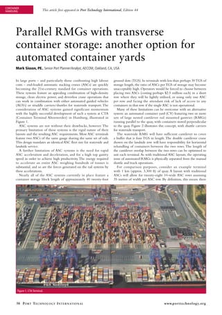
with the highly successful development of such a system at CTA system: an automated container yard (CY) featuring two or more
(Container Terminal Altenwerder) in Hamburg, illustrated in sets of large nested cantilever rail mounted gantries (RMGs)
Figure 1. running parallel to the quay, with containers stored perpendicular
ASC systems are not without their drawbacks, however. The to the quay. Figure 2 illustrates this concept, with shuttle carriers
primary limitation of these systems is the rigid nature of their for waterside transport.
layouts and the resulting ASC requirements. Most ASC terminals The waterside RMG will have sufficient cantilever to cover
feature two ASCs of the same gauge sharing the same set of rails. a buffer that is four TGS in length. The double cantilever crane
This design mandates an identical ASC fleet size for waterside and shown on the landside row will have responsibility for horizontal
landside service. rehandling of containers between the two rows. The length of
A further limitation of ASC systems is the need for rapid the cantilever overlap between the two rows can be optimised to
ASC acceleration and deceleration, and for a high top gantry suit each terminal. As with traditional ASC layouts, the operating
speed in order to achieve high productivity. The energy required zone of automated RMGs is physically separated from the manual
to accelerate an entire ASC weighing hundreds of tonnes is shuttle and truck operations.
substantial, and so are the forces generated on the rail systems by For comparison purposes, consider an example terminal
these accelerations. with 1 km (approx. 3,300 ft) of quay. A layout with traditional
Nearly all of the ASC systems currently in place feature a ASCs will allow for twenty-eight 10-wide ASC rows assuming
container storage block length of approximately 40 twenty-foot 35 metres of width per ASC row. By definition, this means there
Figure 1. CTA Terminal.
38 P o rt t e c h n o l o g y I n t e r n at I o n a l www.porttechnology.org
2. CONTAINER
HANDLING
Figure 2. Section view of transverse RMG options.
will be 28 ASCs available for quay crane support. One km of number of cranes on the terminal (as opposed to the inherent
quay will probably only support 10 quay cranes; in this case there compromises built into an ASC system).
is a 2.8 to 1 ratio of ASCs/quay crane. This assigns more ASCs Another advantage of the parallel cantilever RMG system is
than are necessary in most cases, but without changing the layout the increased number of buffer slots available. In order to position
of the ASC rows, there is no way to reduce the number of ASCs the ASC over the buffer, ASC operations must allow for ASC
without shifting to the unacceptable option of one ASC per run. rails to intermix with buffer areas. This is illustrated in Figure 3,
One option is simply to use wider ASCs, which may make which shows the strad/ASC buffer area at DPW Antwerp.
sense in some cases. The approach carries two big drawbacks, Up to 50 per cent more buffer space will be available
however. Wider ASCs will be heavier, with correspondingly with a cantilever system because there will be no RMG rails
higher costs per ASC – and lower performance. Wider ASCs in the buffer area. The entire waterside cantilever area can be
will also limit landside productivity because the landside ASC continuously striped for buffer storage. This is a particularly
is a conjoined twin to the waterside ASC. The number of each powerful advantage with straddle carrier or shuttle carrier–based
is by definition identical and fixed due to the geometry of the systems because it allows for a great deal more storage. Because
rails. Depending on the transshipment fraction and the level of this buffer storage allows the terminal to smooth out peaks in
peaking in the truck arrival pattern, 28 landside ASCs may be RMG demand, this increased buffer may actually reduce the
a good number to serve the terminal, so any reduction in the number of waterside RMGs required. Landside buffer areas for
number of ASC rows may compromise the performance of the truck service will be similarly larger.
landside ASCs. One waterside RMG should be able to equal or surpass the
The parallel RMG design has the powerful advantage productivity of a single hoist quay crane. The lift dimensions
of decoupling the number of RMGs that can be used for are smaller, and there is no delay for inter-box connector (IBC)
stevedoring as opposed to providing gate service. With RMGs handling or hatch cover operations. Picking or setting containers
running parallel to the wharf, different numbers of cranes can from a CY stack or the buffer area is mechanically simpler than
be ordered for vessel and gate service, optimising the total picking or setting to a ship.
Figure 3. DPW Antwerp Strad/ASC Buffer (Courtesy of Gottwald).
P o rt t e c h n o l o g y I n t e r n at I o n a l 39
3. CONTAINER
HANDLING
Table 1: SySTem highlighTS compared
10-wide ASCs perpendicular to RMGs parallel to quay
quay on same set of rails with transverse storage
Maximum terminal depth with one handoff Over 40 TGS 20 TGS
between waterside/landside CY cranes
Maximum height of machines in use. 1-over-5 1-over-8*
Ratio of waterside CY cranes to quay crane 2.8:1 1:1 to 1.5:1
Minimum spreader spacing parallel to the quay 35 metres 14 metres
Weight of machinery that must accelerate rapidly Entire ASC – perhaps 200 tonnes Trolley + spreader only – perhaps 80 tonnes
to move containers
Typical length of RMG rail per TGS of storage 2.1 metres 0.6 metres
Waterside strad buffer rows per kilometre of quay 112** 164***
Minimum number of horizontal rehandle moves 0 1
(Landside ASC picks from where (Waterside ASC must rehandle once.
waterside ASC drops.) Landside ASC may also need to rehandle
at high levels of utilization.)
*Based on traditional RMGs in Singapore. **Assumes 4 per ASC storage block. ***Assumes striping for access to adjacent slots simultaneously
(6.1 metres between centres)
This means that 10 quay cranes will only require at most 10 (TGS of storage) while only using 30 per cent of the rail length
RMGs for direct service, as opposed to the requirement for 28 required for an ASC system.
ASCs we calculated previously. Depending on the vessel work Transverse RMG systems are not without drawbacks. A
schedule, and the desired gate availability, more RMGs may be sophisticated terminal operating system (TOS) will be required
required to allow for a certain level of horizontal rehandling to achieve high productivity, and the first version of the software
(stack-to-stack transfers) to occur simultaneously with peak will carry more risk than a TOS for an ASC terminal (proven,
vessel activity. Clever use of a large waterside shuttle buffer successful ASC systems can be drawn upon as models to design
may allow less than 10 waterside RMGs to keep up with 10 new ASC terminals). ASC systems are relatively easy to phase into
quay cranes. existing operations (especially existing strad terminals) because
The ratio of waterside RMGs to quay cranes will probably they can be added one row at a time. A parallel system will be
be in the range of 1:1 or 1.5:1, as opposed to the 2.8:1 ratio for more difficult to phase into an existing operation.
10-wide ASCs. Even if large RMGs cost twice as much as an A parallel system will require more horizontal rehandling to
ASC, the overall cost for waterside CY cranes could be as much transfer containers from landside to waterside and vice versa.
as 30 per cent less than that required for an ASC operation. Depending on the working schedule and demand peaking at
Because the containers only need to pass through the legs of the terminal, this may require more RMGs to be purchased,
the RMG crane in the transverse direction, the RMGs can have specifically to allow for rehandling during peak operating periods.
a dimension along the rails of approximately 13 metres (versus The limitations on crane width will probably limit a two-
24 metres with a conventional double-cantilever RMG that has crane system to 20 TGS in depth (i.e., two nested RMGs of 10
to pass the long dimension of the container through the legs of TGS each). Although the higher ratio of ground slots per acre will
the crane). The RMGs can therefore be somewhat lighter and enhance this somewhat, it is still much less CY storage capacity than
cheaper than conventional dual cantiliever RMGs and they can in an ASC system. With RMGs of up to 1-over-8 high, taller stacks
also work closer together. might generate adequate storage if rehandling can be managed.
The relatively narrow RMGs can work at a distance of Otherwise a third row of RMGs may be required to generate
14 metres between machine centres (if need be) to respond to adequate CY capacity. This will increase the cost and complexity
peak demands for either the vessel or the landside. By contrast, a of the system considerably, because the middle set of RMGs will be
10-wide ASC system can only place one spreader every 35 metres required strictly for rehandling between the landside and waterside
along the quay. Achieving effective operations at high density rows. The two systems are compared in Table 1.
will requires a very sophisticated terminal operating system to No one system will be optimal for every terminal. However,
constantly spread the overall working pattern along the length of transverse cantilever RMGs are an appealing option for terminal
the terminal – especially at the gate. operators seeking to develop an automated container yard.
Another important advantage of the parallel system is This is particularly true for terminals of limited depth, or those
a dramatic reduction in the length of RMG rails that will be characterised by short dwell times and correspondingly low
required. A transverse RMG system can service the same volume storage requirements.
abouT The auThor and company
mark Sisson, p.e., leads AECOM’s marine analysis group. He is responsible offers high level planning expertise that includes large-scale regional and port
for business development, project execution, and oversight of research and master planning; marine terminal gates and buildings; system planning for
development of AECOM’s transportation simulation models. Mr. Sisson has 14 transportation, intermodal facilities, maintenance facilities and port operation; and
years of experience managing and executing a wide range of marine terminal advanced computer modeling.
planning, simulation, and analysis projects. enquirieS
aecom is a leader in planning, design and construction management for a Email: mark.sisson@aecom.com
diverse range of ports, harbours and marine facilities worldwide. AECOM also Web: www.aecom.com
40 P o rt t e c h n o l o g y I n t e r n at I o n a l www.porttechnology.org