
Recommended
More Related Content
Recently uploaded
Recently uploaded (20)
Featured
Featured (20)
Circuit diagramz comautomatic-battery-charger-circuit-diagram-circuit-diagramz
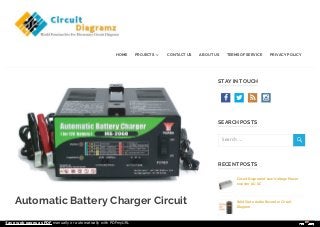
- 1. Automatic Battery Charger Circuit STAY IN TOUCH SEARCH POSTS RECENT POSTS Circuit Diagramof Low-Voltage Power Inverter AC-DC Solid State Audio Recorder Circuit Diagram HOME PROJECTS CONTACT US ABOUT US TERMS OF SERVICE PRIVACY POLICY Search … Save web pages as PDF manually or automatically with PDFmyURL
- 2. Diagram | Circuit Diagramz FEBRUARY 26, 2017 IBRAHEEM AUTOMOTIVE CIRCUIT DIAGRAMS, BATTERY CARGER, HOME AUTOMATION CIRCUIT DIAGRAMS Keeping your car battery constantly charged when the car is not in use appreciably increases the life of the battery. Charging is, of course, normally possible in your garage. The charger described here provides a constant charging current that may, for example, be fed to the battery via the cigarette lighter. Automatic battery charger circuit detail: The charger consists of a mains transformer, Tr1, bridge rectifier B1and smoothing capacitor C1. The charging current through the regulator, IC1 and the switched series resistors is 107 mA (47Ω); 230 mA (22 Ω); 500 mA (10 Ω) or 1A (5 Ω). Diodes D1D4 indicate the position of the switch. Transistor T1, resistor R1 and diode D5 ensure the brightness of the diodes. When the battery is not connected the relay is not energized and the mains is switched off. Automatic Battery Charger Circuit Diagram: Auto Power off for Audio Equipment Circuit Diagram Simple DC Voltage Doubler Circuit Diagram NiMH Battery Charger Circuit Diagram SUBSCRIBE TO A CATEGORY Subscribe To ASpecific Category Get Notified Whenever There Is A New Project In Your Desired Category SUBSCRIBE! VIEW ALL CIRCUIT CATEGORIES Amplifier Circuit Diagrams Audio Circuit Diagrams Save web pages as PDF manually or automatically with PDFmyURL
- 3. When the battery is connected C3 is get charged, T4 is switched ON and the relay is energized. The mains is then switched ON and the battery is charged via D7. The consequent voltage drop across D7 causes T3 and T2 to be switched ON, so that the relay remains energized although, since its collector is at +12V, transistor T4 is switched off. Resistor R5 ensures thatC1 is kept charged so that T4 remains off. To ensure that the charger works with flat batteries, the relay contact may be bypassed by S1 which enables the charger to switches ON manually. Note that during constant charging of lead acid batteries there is the risk that water dissolves into hydrogen and oxygen and this will reduce the liquid in the battery. Since sealed batteries cannot be topped up, the present charger is not suitable for this type of battery. Also do not use a current higher than necessary; in most cases 100 mA is ample. Calculator & Measurement Circuit Diagram Softwares Clock & Timer Circuit Diagrams Counter Circuit Diagrams DIY-Tutorials Electronic Keys & Locks Filter Circuit Diagrams Fire Alarm Fun & Game Circuit Diagrams High Voltage Circuit Diagrams Home Automation Circuit Diagrams How-to-draw-circuit- schematic-diagram LCD-LED Display Lights and Display Board Circuits Metering and Instrument Circuits Save web pages as PDF manually or automatically with PDFmyURL
- 4. « Circuit Diagram of Low-Voltage Power Inverter AC-DC The larger currents are intended for charging large NiCd batteries. LEAVE A REPLY Your email address will not be published. Required fields are marked * Comment Name * Email * Website Motor Circuit Diagrams Power Supplies Radio – Wireless Schematic Symbols Security & Saftey Signal Generators Simple Circuits Solar Circuit Diagrams Speed Controller Circuit Diagrams Telephone Related Television – TV Related Three phase circuit Diagrams Tone generator circuit Diagrams UPS – Inverter – Power Generator Circuits USB Circuit Diagrams Save web pages as PDF manually or automatically with PDFmyURL
- 5. POST COMMENT Voltage Regulators Circuit Diagrams Sensors – Tranducers Circuits © 2017 Copyrights and all rights reserved by Circuit-Diagramz.com Privacy & Terms Type the text Save web pages as PDF manually or automatically with PDFmyURL