Flameproof Flanged Pressure Switches FC series
•
1 like•136 views

Flameproof Pressure Switches are designed as per IS2148 for Gas Gr. IIC Flameproof - CE Certification and approved by a leading European Lab – “BASEEFA” for ATEX & ICEEX certificates Various Ranges : from 0 to 150 mm Wc upto 0 to 400 Bar Differential (Dead Band) : Fixed (Within 10% of set value) Or, Adjustable Sensing Element : Diaphragm (PTFE, Neoprene or, SS 316) or Piston Enclosure : Flameproof to group IIC

Recommended
Recommended
More Related Content
What's hot
What's hot (18)
Viewers also liked
Viewers also liked (20)
Similar to Flameproof Flanged Pressure Switches FC series
Similar to Flameproof Flanged Pressure Switches FC series (20)
More from NK Instruments Pvt. Ltd.
More from NK Instruments Pvt. Ltd. (20)
Recently uploaded
Recently uploaded (20)
Flameproof Flanged Pressure Switches FC series
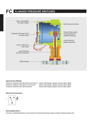
- 1. FC FLANGED PRESSURE SWITCHES Large Flamepaths for better safety Seperate Terminal block for safe wiring Internal ground screw Robust Snap action microswitches for reliable switching Lock Screw for stable set-points Cover chained to main body Large Springs for finer set-points ANSI Flange Approximate Weight : Pressure switches with Aluminium enclosure : Varies with flange, please consult sales office Pressure switches with Grey CI enclosure : Varies with flange, please consult sales office Pressure switches with SS enclosure : Varies with flange, please consult sales office Electrical Connection : Z 2 3 1 SomeApplications : For slurry, colloidal solutions, corrosive & non-corrosive working media (unclean working media), etc.
- 2. FLANGED PRESSURE SWITCHES FC PRESSURE CAPSULE DETAILS No. Description 1. ANSI FLANGE to your specifications please refer table for possible combinations 2. Sealing Ring 3. Diaphragm 4. Disc 5. Plunger 5 3 4 2 Note : wetted parts are mentioned in italics. 1 INSTALLATION DRAWING 145.0 126.0 (5.7) (5.0) CABLE ENTRY 1/2" NPT(F) (Options Avail.) 110.0 (4.3) 26.0 (1.0) Ø7 (Ø 0.27), Mounting Holes, 2nos 1"NB 2500 RF ANSI FLANGE Ø50.8 Ø158.7 (Ø2.0) (Ø6.2) Ø158.7 (Ø6.2) APPROX. DIMENSIONS IN inches
- 3. FC FLANGED PRESSURE SWITCHES RANGE SELECTION TABLE Range Code Range bar (psi) Differential* bar (psi) Maximum Working Pressure bar (psi)Approximate Maximum for "A1" microswitch H01 0.1 - 1.0 (1.45 - 14.50) 0.10 (1.45) As per the class of flange Please consult Sales Office in case you need clarification on availability of maximum working pressure for a particular range. H02 0.1 - 1.5 (1.45 - 21.76) 0.12 (1.74) H03 0.2 - 2.6 (2.90 - 37.71) 0.15 (2.17) H04 0.2 - 3.6 (2.90 - 52.21) 0.20 (2.90) H07 0.5 - 7.0 (7.25 - 101.50) 0.20 (2.90) H10 0.5 - 10.0 (7.25 - 145.04) 0.40 (5.80) H15 1.0 - 15.0 (14.50 - 217.56) 0.50 (7.25) H30 5.0 - 25.0 (72.51 - 362.56) 1 (14.50) H4T 5 - 40 (72.51 - 580.15) 5 (72.51) H1H 10 - 100 (145.04 - 1450.38) 12 (174.05) H2H 7 - 200 (101.53 - 2900.76) 24 (348.09) * Minimum differential increases with setpoint (Graphs available on request) * Differentials of miroswitches A2 through A9 will vary. Differentials for A7 are typically twice that for A1 microswitch. Please indicate specifically the differential value in enquiry/order, when it is critical in your application. FLANGE CODE TABLE (Please refer page no. 228 & 229 for more options) SS316L Hastelloy C276 Monel Titanium Tantalum RF* FF* RF* FF* RF* FF* RF* FF* RF* FF* 150 # 1" NB 2" NB AC AF BS BV DI DL EY FB GO GR IE IH JU JX LK LN NA ND OQ OT 300# 1" NB 2" NB AI AL BY CB DO DR FE FH GU GX IK IN KA KD LQ LT NG NJ OW OZ 2500# 1" NB 2" NB BM BP DC DF ES EV GI GL HY IB JO JR LE LH MU MX OK ON QA QD RANGE AVAILABILITY AS PER BORE SIZES H01 to H04 H07 H10 H15 H30 H2T to H2H 1" NB NA Yes Yes Yes Yes Yes 2" NB Yes Yes Yes Yes Yes Yes *RF = Raised Face *FF = Flat Face
- 4. FLANGED PRESSURE SWITCHES FCOWTOOEFLEPOOFFLGEPESSESWITES st ct GsG ssfct EtySzStcTy vs cstc Ty GoupGoupGoupGoupGoupGoupGoupGoup FSz t F= Ff ssstc, ATEx&IEEx v,t A sIS/IE fGs G.II svf st tst cv ct.W vy fct, yft tf syts tcst. = ASIF ssstc, fxfft ttsc = ASIF ssstc, fxfft tsc = ASIF ssstc, fxfft tscs =SS =Tt GoupGoupGoupGoupGoupGoupGoupGoup .AffstcfsII,t½"PTctystASIf,v.tss,t A.cstc,"BFSSf&SSsscfy Psscfyftvty.Ifytfsttsscf,ctstcststtt tscsss. FAAA = .. = .. = .. = .. = .. = .. = .. = .. T= = = = = = = = = = = tt Psscts= F =TfT Ftcsss =sty szss= f. =Tt & =A. ½"PTts =A. ¾"PTts =A. x. ts =GyI ½"PT ts =GyI ¾"PT ts =GyI x. ts =SS½" PTts =SS ¾"PT ts =SS x. ts Continuous efforts for product development may necessitate changes in these details without notice