Download to read offline

![enc.Frames.Add(BitmapFrame.Create(bitmapImage));
enc.Save(outStream);
System.Drawing.Bitmap bitmap = new System.Drawing.Bitmap(outStream);
return new Bitmap(bitmap);
}
}
private ImageSource Bitmap2ImageSource(Bitmap bitmapImage)
{
// BitmapImage bitmapImage = new BitmapImage(new Uri("../Images/test.png",
UriKind.Relative));
using (MemoryStream outStream = new MemoryStream())
{
MemoryStream ms = new MemoryStream();
bitmapImage.Save(ms, ImageFormat.Bmp);
ms.Seek(0, SeekOrigin.Begin);
BitmapImage bi = new BitmapImage();
bi.BeginInit();
bi.StreamSource = ms;
bi.EndInit();
bi.Freeze();
return bi;
}
}
private void pick_templete_image_Click(object sender, RoutedEventArgs e)
{
Microsoft.Win32.OpenFileDialog dlg = new Microsoft.Win32.OpenFileDialog();
dlg.DefaultExt = ".png";
dlg.Filter = "PNG Files (*.png)|*.png|JPG Files (*.jpg)|*.jpg|GIF Files
(*.gif)|*.gif";
Nullable<bool> result = dlg.ShowDialog();
if (result == true)
{
ImageSource tempImage = new BitmapImage(new Uri(dlg.FileName));
dimg.Source = tempImage;
}
}
private Bitmap bitmapconverter(Bitmap image)
{
Bitmap pic1 = new Bitmap(image.Width, image.Height,
System.Drawing.Imaging.PixelFormat.Format24bppRgb);
return image;
}
private void cmp_Click(object sender, RoutedEventArgs e)
{
BitmapImage srcimg = src_imgBox.Source as BitmapImage;
Bitmap img = BitmapImage2Bitmap(srcimg);
EuclideanColorFiltering filter = new EuclideanColorFiltering();
// set center color and radius
filter.CenterColor = new RGB(255, 10, 10);
filter.Radius = 150;
filter.ApplyInPlace(img);
BlobCounter blobCounter = new BlobCounter();
blobCounter.MinWidth = 5;
blobCounter.MinHeight = 5;
blobCounter.FilterBlobs = true;
blobCounter.ObjectsOrder = ObjectsOrder.Size;
blobCounter.ProcessImage(img);
System.Drawing.Rectangle[] rects = blobCounter.GetObjectsRectangles();
ExtractBiggestBlob filter1 = new ExtractBiggestBlob();](https://image.slidesharecdn.com/22f624a5-fa7a-4990-9274-8fd895ea1400-170124051242/85/project-complete-Copy-12-320.jpg)
![// apply the filter to get original output
Bitmap biggestBlobsImage = filter.Apply(img);
foreach (System.Drawing.Rectangle recs in rects)
if (rects.Length > 0)
{
System.Drawing.Rectangle objectRect = rects[0];
Graphics g = Graphics.FromImage(img);
using (System.Drawing.Pen pen = new
System.Drawing.Pen(System.Drawing.Color.FromArgb(160, 255, 160), 5))
{
g.DrawRectangle(pen, objectRect);
}
g.Dispose();
}
/*Dispatcher.BeginInvoke(new ThreadStart(delegate
{
speechSynthesizer.Speak("Warning!!!");
}));*/
MemoryStream ms = new MemoryStream();
img.Save(ms, ImageFormat.Bmp);
ms.Seek(0, SeekOrigin.Begin);
BitmapImage bi = new BitmapImage();
bi.BeginInit();
bi.StreamSource = ms;
bi.EndInit();
bi.Freeze();
Dispatcher.BeginInvoke(new ThreadStart(delegate
{
dimg.Source = bi;
}));
}
}
}
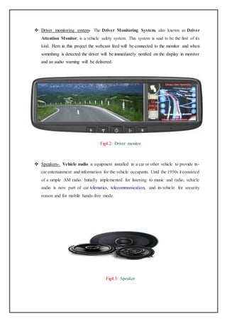
Fig4.4: Main Code](https://image.slidesharecdn.com/22f624a5-fa7a-4990-9274-8fd895ea1400-170124051242/85/project-complete-Copy-13-320.jpg)
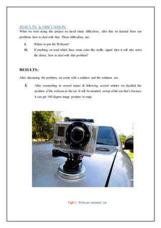

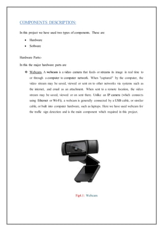
This project report summarizes a student project to develop an automatic traffic sign and signal detection system. The report was submitted by three students - Milan Mahadani, Piyush Benia, and Nishat Tarik - to fulfill requirements for their Bachelor of Technology degree in Electronics and Communication Engineering from Maulana Abul Kalam Azad University of Technology. The report provides background on the project, describes the components used including a webcam and main code, explains the operation and flow, discusses results from testing the system, and outlines potential applications and advantages of the system. Certification is provided from the project guide and department head to verify completion of the project.