
Recommended
More Related Content
What's hot
What's hot (16)
Similar to Flowhub Bulletin
Similar to Flowhub Bulletin (20)
Flowhub Bulletin
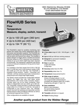
- 1. 1290 E. Waterford Ave. Milwaukee, WI 53235 Tel: (414) 769-6400 Fax: (414) 769-6591 E-mail: sales@webster-inst.com Webster Instruments (A Division of Webtec Products) FlowHUB Series Flow Temperature Measure, display, switch, transmit ● Up to 100 US gpm (360 lpm) ● Up to 6,000 psi (420 bar) ● Up to 194 °F (90 °C) The FlowHUB is ideal for condition monitoring, test Features stands and closed loop control applications both for ● 5 flow sizes range of: 0.25 - 100 US gpm, 1 - 360 fluid power and lubrication systems. The FlowHUB can measure and display flow and temperature readings as lpm well as switch and transmit flow values. This enables a ● Up to 6,000 psi (420 bar) working pressure system designer to trigger alarms, shutoffs and transmit real-time values to a PLC using just one component, ● Designed for permanent installation instead of up to six which might have been required (few wearing parts) conventionally. This represents a significant cost saving ● Easy to operate in terms of reduced complexity of wiring and far fewer 4 digit LED display components. 3 large keys It is available in five flow ranges from 0.25 to 100 US gpm (1 to 360 lpm) and in two pressure ranges 3,000 ● Accuracy better than 3% FSD and 6,000 psi (210 and 420 bar). The FlowHUB is ● Repeatability better than 1% available in three versions - ‘Switch’, ‘Transmitter’ and ‘Ultimate’, all three versions have built in temperature ● Temperature measurement built-in measurement and a large bright digital display. ● Wide range of options: The 'Switch' version provides two configurable switched Choice of analog outputs V or mA outputs; the trigger flow rate, time delay, sense Two programmable switches/alarms (above/below) and normal mode (normally closed / Complete with adaptors fitted (JIC or BSP) normally open) can all be freely configured. Each Engineering units gpm / F (lpm / C) switch is independent and can switch up to 500 mA. The 'Transmitter' version provides a conditioned analog ● Easy installation output either 0 to 5 Volts or 4 to 20 mA - full scale is Mount in any orientation configurable to any maximum flow. The 'Ultimate' No special piping required version has both the switches and transmitter and the Allows reverse flow highest pressure rating of 6,000 psi (420 bar) as well as an enhanced response time of 50 ms. ● Traceable calibration on request Other configurations are available on request. ● Patent Pending Design Another quality product from the Webtec Range 04/09 FLOWHUB-BU-USA-2310.pdf
- 2. Specification Functional Electrical specification Flow range: see model configuration Supply voltage: 15 to 30 VDC class 2 supply only Pressure range: see model configuration Typical current: 35 mA Operating temperature: ambient: 41 - 104°F Maximum current excluding switch current: 60 mA (5 to 40 °C) Switch current: 500 mA per switch max. Fluid type: hydraulic oil Switch Voltage: Supply voltage - 0.5 V Fluid temperature: 41 - 194 °F (5 to 90 °C) Connector type: M12 - 5 pin male Accuracy: ± 3% of full scale at 21 cSt Voltage output: minimum load = 10K Ohms (higher accuracy on request) Current output: maximum load = (supply voltage x 46) Repeatability: Better than ± 1% - 200 ohms Response time: 150 ms (Switch and Transmitter), 50 ms (Ultimate) Protection: Designed to meet IP64 / NEMA4 Weight: 4.4 lbs (2 Kg) Installation Dimensions in Inches (Millimetres) 1.96 (50) A/F (Each End) 5.03 (127.9) R1 .11 (28 .3) 2.36 (60) 0.47 2.12 (54) (12.0) 3.93 (100) 1.62 (41.2) 9.07 (230.4) Flow versus Pressure Drop (at 21 cSt in forward direction) Flow (US gpm) 0 10 20 30 40 50 60 70 80 90 100 110 100 360 lpm (100 US gpm) 7 90 6 80 Pressure Drop (bar) Pressure Drop (psi) 5 70 240 lpm (64 US gpm) 60 4 50 3 40 120 lpm (32 US gpm) 30 60 lpm (16 US gpm) 2 20 30 lpm (8 US gpm) 1 10 0 0 0 20 40 60 80 100 120 140 160 180 200 220 240 260 280 300 320 340 360 380 400 Flow (lpm)
- 3. Model configuration Examples US HF100 - TRNMA-3 - S100V Code 1 Code 2 Code 3 Above model number is a FlowHUB Transmitter: Flow range: 2 - 100 US gpm, Maximum pressure: 3000 psi (210 bar), Temperature: °F, Analog output: 4 - 20 mA, no switches, 1 5/16” 37 Deg JIC Male Flare. EU HF360 - TRNMA-3 - B100V Code 1 Code 2 Code 3 Above model number is a FlowHUB Transmitter: Flow range: 8 - 360 lpm, Maximum pressure: 210 bar (3,000 psi), Temperature: °C, Analog output: 4 - 20 mA, no switches, 1” BSPP adaptors. Step 1 - Choose flow range and engineering units US flow range (US gpm and °F) EU flow range (lpm & °C) Code 1 Flow range Standard adaptors Code 1 Flow Range Standard adaptors HF008 0.3 - 8 1 1/16” or 3/4” JIC Male HF030 1 - 30 1/2” or 3/4” BSPP HF016 0.5 - 16 1 1/16” or 3/4” JIC Male HF060 2 - 60 1/2” or 3/4” BSPP HF032 1 - 32 1 1/16” or 1 5/16 JIC Male HF120 4 - 120 3/4” or 1” BSPP HF064 2 - 64 1 5/16” JIC Male HF240 8 - 240 1” BSPP HF100 2 - 100 1 5/16” JIC Male HF360 8 - 360 1” BSPP Step 2 - Choose electronics and maximum pressure Electronic control and maximum pressure options Code 2 Maximum working pressure Function description SWTNA-3 3,000 psi (210 bar) Two programmable switches TRN5V-3 3,000 psi (210 bar) Analog output 0 - 5 Volt TRNMA-3 3,000 psi (210 bar) Analog output 4 - 20 mA ULT5V-6 6,000 psi (420 bar) Two programmable switches, analog output 0 - 5 Volt ULTMA-6 6,000 psi (420 bar) Two programmable switches, analog output 4 - 20 mA Step 3 - Choose adaptors Adaptors SAE options BSPP options Code 3 Description Code 3 Description S050V 3/4”JIC Male B050V 1/2”BSPP S075V 1 1/16” JIC Male B075V 3/4”BSPP S100V 1 5/16” JIC Male B100V 1” BSPP Custom configurations are available (volume dependant), please contact sales. Build your own FlowHUB - - Code 1 Code 2 Code 3
- 4. Filtration Reverse flow operation It is recommended that a 25-micron filter is installed The FlowHUB will allow reverse flow but it will not in the hydraulic circuit prior to the FlowHUB. measure the flow rate. The pressure drop in reverse flow is considerably higher then that for forward flow. Calibration Please see chart below for details. The above specification is met without ‘wet’ calibration - if full traceable calibration is required Reverse flow pressure drop then please state at the time of ordering - this is an Pressure drop at Pressure drop at option and will incur an additional charge. As Flow range 1/2 full flow full flow standard it is completed at 21 cSt (ISO 32 oil at 122 100 US gpm (360 lpm) 70 psi @ 180 lpm 260 psi @ 360 lpm °F / 50 °C) 64 US gpm (240 lpm) 40 psi @ 120 lpm 130 psi @ 240 lpm 32 US gpm (120 lpm) 110 psi @ 60 lpm 400 psi @ 120 lpm Construction material 16 US gpm (60 lpm) 30 psi @ 30 lpm 90 psi @ 60 lpm 8 US gpm (30 lpm) 9 psi @ 15 lpm 28 psi @ 30 lpm Flow body: High tensile aluminium 2014 T6 Internal parts: Brass CZ121, Stainless steel 316, (1 bar = 14.5 psi, 10 lpm = 2.64 USgpm) Steel 212A42 Adaptors: High pressure - Steel 212A42 zinc Fluid viscosity plated and clear trivalent passivate. The performance of the FlowHUB can be affected by Standard - Steel 230M07 zinc plated. the viscosity of the fluid measured. All units are Electronics enclosure: Die cast aluminium designed to meet the specification at a viscosity of 21 cSt, which is a typical kinematic viscosity for a Operation hydraulic fluid operating at 50°C. The shaded area of All FlowHUBs work on the same theory - the fluid flow the table shows the expected range of viscosities that is used to move a magnet which is mounted within a can be used by the FlowHUB (models 8, 16, 32, 64 piston, the distance moved is proportional to the flow US gpm & 30, 60, 120, 240 lpm) with minimal effect rate. This movement is measured by a sensitive on the accuracy (less than ± 3% FS). FlowHUBs can magnetic device. The piston is designed to minimise be specially calibrated at a different viscosity or we the effects of variations in temperature and viscosity can advise on the expected error when it is used at and built-in flow conditioning eliminates flow swirl and other viscosities. For more detailed information about allow any connection to be made at the input without viscosity changes and information on the 360 lpm or the normal 10 diameters of straight pipe. The on- 100 US gpm models please contact Webtec. board electronics condition the signal and convert the linear movement to fluid flow. The FlowHUB also Table showing kinematic viscosity (cSt) allows unmeasured flow in the reverse direction. of different mineral oils at specific temperatures Installation Fluid type The FlowHUB can be installed in any orientation and Temp °C ISO15 ISO22 ISO32 ISO37 ISO46 ISO68 since the unit has built-in flow conditioning, no 0 85.9 165.6 309.3 449.9 527.6 894.3 lengths of straight tube are needed. As the unit 10 49.0 87.0 150.8 204.7 244.9 393.3 contains a sensitive magnetic device it is 20 30.4 50.5 82.2 105.5 127.9 196.1 30 20.1 31.6 48.8 59.8 73.1 107.7 recommended to mount away from strong magnetic 40 14.0 21.0 31.0 36.6 44.9 63.9 fields and large ferrous objects, a distance of 80 mm 50 10.2 14.7 20.8 23.9 29.4 40.5 is recommended. For this reason it is also 60 7.7 10.7 14.7 16.5 20.2 27.2 recommended to use only the adaptors supplied as 70 6.0 8.1 10.9 12.0 14.6 19.2 different shaped adaptors can effect the readings. 80 4.8 6.4 8.4 9.1 11.1 14.3 90 4.0 5.2 6.6 7.2 8.7 11.1 100 3.3 4.3 5.5 6.0 7.1 8.9 Grey area denotes operation with standard calibration will give flow accuracy of better than 3% FS. Certificate No.8242 Webster Instruments reserve the right to make improvements and changes to the specification without notice