More Related Content
Similar to Arc flash hazard labeling do's and don'ts
Similar to Arc flash hazard labeling do's and don'ts (20)
Arc flash hazard labeling do's and don'ts
- 1. Arc Flash Hazard Labeling
Do’s and Don’ts
© 2008 ESA, Inc.
ESA • PO Box 2110 • Clackamas, OR 97015 • Tel: 503.655.5059 • Fax: 503.655.5542 • www.EasyPower.com
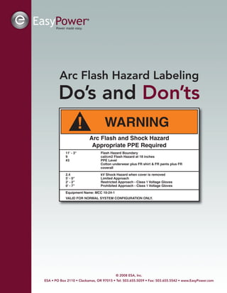
! WARNING
Arc Flash and Shock Hazard
Appropriate PPE Required
11' - 3" Flash Hazard Boundary
9 cal/cm2 Flash Hazard at 18 inches
#3 PPE Level
Cotton underwear plus FR shirt & FR pants plus FR
coverall
2.4 kV Shock Hazard when cover is removed
5' - 0" Limited Approach
2' - 2" Restricted Approach - Class 1 Voltage Gloves
0' - 7" Prohibited Approach - Class 1 Voltage Gloves
Equipment Name: MCC 10-24-1
VALID FOR NORMAL SYSTEM CONFIGURATION ONLY.
- 2. © 2008 ESA, Inc. | Arc Flash Hazard Labeling Do’s and Don’tsPage 2
Overview
With industry adopting NFPA 70E, and Canada’s Z462 as the consensus electrical safety standard, North
American facilities and many of their counterparts worldwide are performing arc flash hazard studies to label
their electrical equipment for safety. The requirement for arc flash hazard labeling is found in the National
Electrical Code, Article 110.16 for new equipment, NFPA 70E-2009 Article 130.3(C) for existing equipment, and
OSHA 1910.335(b)(1) for general safety hazards.
There are as many different ways to label equipment as there are engineers and electricians in industry.
Unfortunately, many of the methods being used are incorrect and may actually decrease worker safety, while
increasing your company’s liability should an accident occur. This article supplies a safe-approach reference
developed through years of experience working with engineers and electricians on their arc flash hazard
projects. The viewpoints expressed in this paper are provided as a guide to industry, recognizing that the NEC,
NFPA, and OSHA set the standards but do not cover the myriad of questions associated with labeling the
different types of electrical equipment in industry.
Common Terms: AFH (arc flash hazard), NFPA 70E (National Fire Protection Association – Standard for
Electrical Safety in the Workplace), OSHA (Occupational Safety and Health Administration), CSA Z462
(Canadian Standards Association - Standard for Electrical Safety in the Workplace), PPE (Personal Protective
Equipment), NEC (National Electrical Code), ANSI (American National Standards Institute).
Don’t label for Energized Work — Do label to warn of hazards
In the majority of facilities hoping to obtain NFPA 70E compliance, the most prevalent mistake we see is
performing an AFH study for the sole purpose of labeling equipment. Following the study, the plant continues
the same day–to-day operations, only now the electricians wear PPE as labeled on the equipment.
Two myths need to be dispelled: 1) Arc flash hazard labeling alone does not provide 70E or OSHA compliance
and 2) Labeling does not eliminate the requirement for work permits, safety programs, or training and planning
when working on energized equipment. What this means in simplified terms is that a facility cannot perform
energized work based solely on the fact that the equipment is labeled and the worker is wearing the
appropriate PPE as designated on the label.
Arc Flash Hazard labels should be applied to warn personnel of a potential hazard. Labels should not be used
to “assess” a hazard, select PPE levels, or perform energized work based on the information provided on the
label. These tasks are part of the planning, documentation and work permit process required by NFPA 70E
130.1. Arc Flash hazard information such as PPE level, incident energy, and boundary information shown on
many labels should only be used as a cross-check with the information provided in the work permit process.
Labels should not be used to “assess” a hazard, select PPE levels,
or perform energized work based on the information provided on the label.
- 3. © 2008 ESA, Inc. | Arc Flash Hazard Labeling Do’s and Don’ts Page 3
Label Worst Case
NFPA 70E, 2009 Article 130.3(C) requires AFH labels to show the incident energy or the required PPE level for
that equipment. Most labels being applied today list both, along with a host of other items such as AFH
boundaries, approach boundaries, glove requirements, etc. Whatever options you select, the listed incident
energy or PPE should be the “worst” case for that equipment.
Many companies choose to label switchgear, for instance, with a working distance of 24-36 inches. They do this
based on the assumption that the only work being done on the equipment is racking out the breaker. However,
that is not a realistic assumption. What happens if the breaker racking mechanism sticks and the electrician
positions himself/herself closer to fix the mechanism? What if there are other work tasks that crop up requiring
a closer working distance?
Other factors contribute to “worst” case results such as generators being turned on/off, motors being turned off
or on during a shutdown condition, etcetera. These variables must be considered in a “worst” case calculation.
AFH labeling with values less than “worst” case requirements will increase your company’s liability, should there
be an arc flash accident. The attorneys working for the injured parties will easily prove that a higher incident
energy existed at a standard working distance of 18 inches or with a different mode of operation, and show the
equipment label did not warn the party of potential increased danger, concluding pure and simple negligence.
This is not to say that you cannot rack a breaker out using the calculated incident energy at a longer distance,
say 36 inches. The important point to note is that each work permit and planning procedure documents a
specific work task and its associated requirements. If that task or working distance changes, a new work permit
is required along with the possible need for new safety procedures. The employee will be properly briefed and
protected if this procedure is followed.
Label with only one working distance and one PPE requirement
When equipment has multiple AFH labels with different working distances, and different PPE levels, it is a
recipe for disaster in the making. With multiple options, workers now have the opportunity to select the
label/PPE of their choice without management oversight. It is human nature for all of us to assume there will not
be an incident. It usually goes something like this.
The worker looks at the front side label and reads an incident energy of 12.4
cal/cm2 and a PPE level of #3.The backside label (breaker terminals) is labeled
3.6 cal/cm2, PPE level #1, due to the feeder breaker instantaneous trip units.The
employee thinks: 1) “Man it’s really hot today. I bet the humidity is 95%.” 2) “I’ve
done this same task for the past 26 years without an incident.” 3) “It’s almost
time to go home. I really don’t want to go back and get in that stupid tank suit.”
AFH labeling with values less than “worst” case requirements will
increase your company’s liability, should there be an arc flash accident.
- 4. © 2008 ESA, Inc. | Arc Flash Hazard Labeling Do’s and Don’tsPage 4
When given the choice, most people are going to take what they perceive as the easy way out. If this worker
initiates an arc flash incident wearing PPE level #1 and ends up with third degree burns over half his body, who
will be blamed and found liable? The objective reader may easily point the blame at the worker for being lazy or
lacking intelligence. However, his attorney is going to claim: 1) The labeling process was confusing. My client
could not tell which label applied to which area of the equipment. 2) The labels did not denote specific work
tasks for the equipment, and they did not segregate boundaries on the equipment for their application. 3) My
client was not properly trained by the company to distinguish how different labels apply to Manufacturer XYZ’s
equipment. In any arc flash hazard lawsuit, if there is any doubt regarding whether or not the corporation
followed the industry mandates, the court jury or judge will rarely side with the corporation. In spite of the fact
that the worker was lazy or broke company policy, the jury will see a traumatized man with multiple skin grafts,
scarred for life and unable to ever work again.
It is critical to label the equipment using only one (worst case) energy PPE level and one working distance per
equipment. Following this procedure will minimize training requirements, confusion, and liability. Additionally, we
strongly recommend standardizing on an 18 inch working distance for all equipment. Considering every
enclosed equipment type from 120V through 34.5 kV, there will always be some work task that will put a worker
in the 18 inch range. Labeling some equipment for 24 or 36 inches, and others for 18 inches adds confusion to
your safety program. If workers want to manage down the PPE level for a “specific task” by working from an
increased distance, this is properly done by an Article 110.7(F) Hazard /Risk assessment and a detailed Article
130.1 work permit combined with proper work procedures and training.
The only exception to this rule might be for isolated and barrier protected main breakers in a switchgear lineup.
Many facilities prefer to label the incoming switchgear breaker separately from the bus and feeder breakers.
This allows work on the feeder breakers to be conducted under the lower PPE level provided by the main
breaker. The problems with this approach are threefold. 1) Workers could follow the ratings on the lower rated
bus label beginning their work in the appropriate area and either accidentally, or intentionally, transition to the
main breaker compartment where the AFH energy will typically be “extreme danger”. 2) This method promotes
work on the bus and feeder breakers using only a label, potentially bypassing the necessary Article 130.1 work
permit requirements. 3) This method can only be done on isolated and barrier protected main devices. In most
facilities this applies only to a minor portion of equipment; therefore, additional training will be required to
ensure all workers understand the specific restrictions for this particular labeling method.
Label per ANSI Z535.4
ANSI Z535.4 provides the consensus standard used in North America for safety labels. Deviation from this
standard is allowed, but courts will rule that Z535 is the minimum acceptable standard. This means that
deviation from this standard requires that you prove increased effectiveness is provided by your equipment
labeling program.
Examples of the Z535 standard are shown below.
- 5. © 2008 ESA, Inc. | Arc Flash Hazard Labeling Do’s and Don’ts Page 5
The Z535 format includes a triangle with an exclamation mark which is the safety alert symbol. This symbol
appears to the left of the signal word DANGER, WARNING or CAUTION and signifies that there is a personal
injury hazard potential. The ANSI Z535.4-2002 revision makes this symbol a universal element on all U.S.
personal injury-related safety signs and labels.
The Z535 standard requires that a product safety label communicate the following:
• the type of hazard
• the seriousness of the hazard
• the consequence of interaction with the hazard, and
• how to avoid the hazard
We recommend labels that use the orange “Warning” label rather than the red “Danger” label. The reason for
this is that “Danger” often denotes an immediate problem such as open or exposed wiring or moving equipment
and indicates the need to stay away. “Warning” alerts the individual to a potential problem dependent on user
interaction. This reasoning is subjective and the user should select a color based on their safety program
objectives.
We have seen more than one facility color code labels based on PPE levels. Red=Extreme danger (> 40
calories), Orange =PPE Level 4 (> 25 calories), Yellow = PPE Level 2 (> 8 calories), and Green= PPE Level 0
(< 2 calories or <1.2 calories). Because ANSI has selected three colors to denote specific levels of hazard, we
do not recommend color coding AFH labels based on PPE level. Company defined color coding confuses the
basic ANSI color coding and subjectively encourages levels of danger in the facility. In reality, an arc flash of 8
calories can have the same life changing impact as that of a 15 calorie event. Additionally, color coding any
AFH label with green, conveys the message that there are no potential hazards in this equipment, since green
is the universal color for “go” or “safety”. A PPE level of 0 does not mean that there are no potential hazards in
this equipment.
- 6. © 2008 ESA, Inc. | Arc Flash Hazard Labeling Do’s and Don’tsPage 6
The following label is an example of a thorough ANSI Z535 AFH label.
ANSI Z535 labels are the most recognized safety label in North America. Using standardized labels minimizes
safety training requirements for both employees and contractors, thereby reducing liability on the part of the
facility. Custom labels will require specialized training not only for your company employees, but also for every
contractor coming onsite. Note: Labels that display company logos, flashy colors, or vendor advertising should
be avoided, as they distract from the warning!
How Many Labels per equipment?
A frequently asked question is how many labels are
enough? Obviously if one is good, more is better – right?
This philosophy has both positive and negative aspects that
must be considered. The more labels used the higher the
visibility factor. However, too many labels clutter the
objective and cause workers to ignore the warning.
For the MCC above, a simple one-word “warning” label was
used without providing specific PPE, boundary information,
or hazard levels. This minimizes clutter, however, if you take
a step back and see 50-75 of these labels the clutter
becomes obvious. The clutter is even more prevalent and
confusing if the standard AFH information is included on
the labels. The worker looking at the MCC must then
determine 1) Which label is important? 2) If the labels are
different, what information applies to this task? 3) How do I react to these circumstances?
! WARNING
Arc Flash and Shock Hazard
Appropriate PPE Required
11' - 3" Flash Hazard Boundary
9 cal/cm2 Flash Hazard at 18 inches
#3 PPE Level
Cotton underwear plus FR shirt & FR pants plus FR
coverall
2.4 kV Shock Hazard when cover is removed
5' - 0" Limited Approach
2' - 2" Restricted Approach - Class 1 Voltage Gloves
0' - 7" Prohibited Approach - Class 1 Voltage Gloves
Equipment Name: MCC 10-24-1
VALID FOR NORMAL SYSTEM CONFIGURATION ONLY.
- 7. © 2008 ESA, Inc. | Arc Flash Hazard Labeling Do’s and Don’ts Page 7
When deciding quantity, another factor to consider is the cost of replacing the labels when system changes
take place or when the IEEE-1584 calculation changes are released in 2010-2011? Relabeling an entire facility
is time consuming and expensive.
A common sense approach to labeling seems to make the most sense for general applications. Labeling with
one high profile 4x6 inch or 6x8 inch label front-side and back-side should be sufficient for most switchgear,
switchboard, and panelboard applications. For larger equipment such as long switchboards, two labels should
be sufficient. Labels should be placed where clearly visible; the top is preferable when equipment type allows.
See examples below.
For feeder bus duct, labeling every 15-25 feet with the bus duct “worst case” label, provides sufficient warning
of the potential hazard. It is not necessary or recommended to label each plug-in for the reasons already
stated.
For some equipment, additional labels should be considered at potential entry or work points. Examples might
include open bus vaults or large junction boxes where access can be obtained from several sides.
Examples
This section provides multiple labeling examples for different types of electrical equipment, which can be
modified or extrapolated to fit your system. For some equipment types, multiple options will be provided.
Panels
Panels are typically of box construction with a fixed backing plate attached
to a beam, or wall mounted. The front of the panel, which provides opening
access, is bolted in place. The front cover typically has a hinged opening,
which allows viewing and operation of the breakers. For standard 42 circuit
lighting panels, the typical labeling procedure is one label on the main cover,
top center. See Figure-1.
Figure 1
- 8. © 2008 ESA, Inc. | Arc Flash Hazard Labeling Do’s and Don’tsPage 8
Panelboards
Panelboards, sometimes called distribution panel boards (DPB), or
distribution boards are larger than a standard panel and may range from
400-1200A. They are typically standalone, but smaller units may be wall or
beam mounted. Larger units may be accessible front and back side via
bolted covers. For standard DPB’s, typical labeling procedures is one label
on the main cover, top center. For the example shown in Figure-2, the label
was moved to the bottom to prevent covering the cooling vents.
Panelboards, do not have isolated and barrier protected main breakers
unless specially ordered and should always have only one label.
Dry Type Transformers
Dry type transformers typically have
a bolted on face plate section with
exposed terminals behind the face
plate. Since this is the main access
point, it is usually not necessary to
label the other sides.
Larger units may have two or more cubicles and can be labeled
with one or multiple labels.
Figure 2
Figure 3
Figure 4
- 9. © 2008 ESA, Inc. | Arc Flash Hazard Labeling Do’s and Don’ts Page 9
Variable Frequency Drives,
and Control Cabinets
Variable frequency drives and control cabinets
are typically hinged front opening units with an
open, exposed incoming main breaker. The
incoming breaker or fuse is typically not isolated
or barrier protected from the other sections and
therefore cannot be used for AFH protection. Like
other cabinets, one “worst case” label is typically
sufficient. See Figure-5.
In the example of Figure-6 the incoming line
section (upper left section) is not isolated from
the main SCR/reactor compartments. Therefore,
any arc initiation will propagate instantly to the
incoming protection and prevent its operation.
In the drive example shown in Figure-7 below, the
incoming main breakers shown in the right side cubicle
appear to be properly isolated by a section divider. Once
this has been verified by the facility, the lower value
incident energy/PPE level can be labeled on the other
sections. Facilities employing this approach assume the
three liabilities listed in the previous section entitled,
“Label with only one working distance and one PPE
requirement”. We recommend that only the “worst case”
label for the complete equipment be used. If they are not working in the main incoming section, we recommend
that users manage down the required PPE level via work permit and strict safety procedures.
Figure 5
Figure 6
Figure 7
- 10. © 2008 ESA, Inc. | Arc Flash Hazard Labeling Do’s and Don’tsPage 10
Switchboards and Switchgear
Switchboards and Switchgear are the standard
for low voltage distribution equipment.
Switchgear by definition has isolated and barrier
protected cubicles, rack-in air frame
breakers/switches, and isolated bus.
Switchboards may have similar attributes but will
most likely be equipped with molded case or
insulated case breakers, or fuses in non-isolated
cubicles with non-isolated bus work. By special
order, the main breaker/switch can be isolated,
enhancing arc flash protection.
For a typical 4 section or less switchgear lineup,
only one label (worst case) on the front side is
necessary. See Figure-3 below. For longer
sections additional labels can be applied every
5-10 feet. Since both front and back-side
switchgear covers are hinged, the back-side
covers should also be labeled.
For switchboards, the back-sides are typically
open exposed bus with bolted covers, which
should prevent access. Labeling should be
optional since access is not easily obtained.
If the user prefers to label the main breaker section separately, thereby providing a lower PPE level label for the
bus and feeder breakers, the main incoming section should be sectioned off to clearly demark the switchgear.
The main section will most likely be labeled “Extreme Danger” unless specialized relaying has been
implemented, and the feeder breaker/bus section will typically have a lower PPE level rating. See Figure-9
below. One label on each side of the demarcation is typically sufficient, although the back-side should also be
labeled if it is hinged and easily opened.
Note: ESA recommends “worst case” labeling for all
switchgear and does not advocate demarcation lines to
sectionalize equipment with different labels.The
procedure shown here is presented only to show the
proper method for demarcation. ESA recommends
NFPA 70E Article 130.1 Work Permits, safety
procedures, and proper planning for reduced
PPE level work on different sections.
Figure 8
- 11. © 2008 ESA, Inc. | Arc Flash Hazard Labeling Do’s and Don’ts Page 11
Some switchgear line-ups come in
combination units with a connected
transformer and high voltage primary switch.
These should be sectionalized with a clear
demarcation line for section labeling. The
preferred method is shown in Figure-10,
where the “worst case” low voltage arc flash
results extend from the transformer section
through the low voltage switchgear. This
method can be applied to all switchgear,
switchboard, and panelboard combination
units, with or without main breakers. Note that
the transformer HV terminals would actually
be labeled with the higher incident energy
value LV label, since the HV terminals are in
the same cabinet as the LV terminals. The HV
fused switch terminals should be labeled
separately.
Figure 9
Figure 10
- 12. © 2008 ESA, Inc. | Arc Flash Hazard Labeling Do’s and Don’tsPage 12
For switchgear with an isolated and barrier protected main breaker, the bus and feeder breaker section can
typically be sectionalized with a lower incident energy label. Once again, clear demarcation and additional
training is required. See Figure-11. This same labeling method can be applied to enclosed High Voltage
Switchgear and fused disconnects also.
Feeder Bus Duct
Low Voltage feeder bus duct has become the standard
for many manufacturing facilities where production
requirements require frequent machine tool change out,
updating assembly lines, etc. The ease of simply
plugging in a new feed for a different machine tool has
many advantages. The disadvantages of feeder bus duct
are that the phase conductors are typically not insulated,
the bus structure can flex and become misaligned
creating a hazard when plugging in or removing plug-ins,
and the long lengths of some runs create short circuit
disparities between the beginning and end sections,
which create protection difficulties. All three of these
issues relate directly to the best method for labeling a
feeder bus duct. It is beyond the scope of this paper to
explain the proper procedure for calculating the worst
case PPE level for a feeder bus duct. However, it should
be sufficient to recognize that there can typically be
several different PPE levels along a feeder bus duct
length, due to the changing impedance and varying short
circuit levels.
Figure 11
Figure 12
- 13. © 2008 ESA, Inc. | Arc Flash Hazard Labeling Do’s and Don’ts Page 13
We recommend that the worst case PPE level of the entire bus duct length be used to label the entire bus duct.
We do not recommend different labels for different plug-ins, or the need to label each plug-in. A 4”x6” or 6”x8”
label every 10-20 feet should be sufficient. See Figure-12.
Often, bus duct can have multiple bends which can hide a label from view. Consideration should be given to
labeling these sections if there is potential for plug-ins. For vertical riser sections, it is probably only necessary
to label at each floor level where plug-ins occur. Labeling should include both front and back sides of all runs.
Motor Control Centers
Motor control centers raise more labeling questions than almost any other type of equipment. The reason for
this is the number of individual buckets or units in the equipment. Does each bucket require a label, or can the
equipment be labeled using the same procedures as described for other equipment?
The key factor in labeling MCC’s is understanding that
the breaker/fuse in the individual motor starter bucket
will not protect the worker if they initiate an arc flash in
that bucket. The initial arc caused by the worker will
instantly ionize the air in the bucket. This will propagate
the arc to the breaker/fuse primary terminals, which will
sustain the arc and prevent device operation. Therefore,
the arc energy for each individual bucket is controlled
by the remote tripping of the breaker/fuse that feeds the
MCC. This is the same issue found in panelboards,
switchboards, etc. Since there is only one arc energy for
the entire MCC, we recommend labeling in the same
manner as the other equipment – one “worst case” label
as shown in Figure-13.
If the MCC extends more than 3-4 sections, additional
labeling can be applied as necessary. MCC’s are
manufactured with bolted on side and back sections,
preventing inadvertent exposure of the main and
vertical buses. Additionally, most MCC’s are located
either back-to-back in the center of the room or against
the wall preventing opening of the MCC back panels.
Therefore, labeling the side and back sections of an
MCC is typically not required.
Figure 13
- 14. © 2008 ESA, Inc. | Arc Flash Hazard Labeling Do’s and Don’tsPage 14
Junction Boxes and Miscellaneous Equipment
Junction boxes come in many forms, from standard conduit interconnections, to motor terminal connections. In
a typical facility, there could be hundreds-of-thousands of boxes with accessible electrical wires. NFPA 70E
130.1 indicates it is imperative to train all workers that every electrical equipment is a potential AFH that
requires a work permit before any equipment is opened, including junction boxes.
The key factor in deciding labeling protocol for junction boxes may come down to how frequently are they
opened? If they are never opened, the need for labeling would follow the guidelines as provided for the back of
an MCC or switchboard lineup. However, if they are opened on a routine basis, labeling is appropriate and
necessary. According to Article 130.1, either option still requires a work permit.
Summary – Do’s and Don’ts of AFH labeling
This paper provides guidelines and examples for proper AFH labeling to increase worker safety and minimize
corporate liability. A series of equipment examples have been provided to guide users in labeling decisions. As
in any type of safety procedure, common sense is the key.
Do’s
Do label “WORST” case energy or PPE level. Consider all possible modes of operation.
Do label per ANSI Z535.4
Do label using only one color, Orange for Warning or Red for Danger.
Do standardize on only one working distance – preferably 18 inches for all labels in a facility.
Manage down PPE levels using work permits stating increased distances based on work task and
proper safety procedures.
Label to warn of potential danger, not for the purpose of working on the equipment.
Do use common sense in your hazard labeling.
Do implement NFPA 70E Article 130.1 work permit requirements for all energized work even if a label
is present.
Don’ts
Do not label each MCC bucket, breaker/fuse cubicle, or plug-in (busway).
Do not label using colors for PPE level.
Don’t label with multiple distances or PPE levels on the same equipment.
Don’t make it complicated.
Don’t substitute labeling for NFPA 70E Article 130.1 work permit requirements.