
Recommended
Recommended
More Related Content
What's hot
What's hot (11)
Similar to 1008 a specs valves
Similar to 1008 a specs valves (20)
Recently uploaded
Recently uploaded (20)
1008 a specs valves
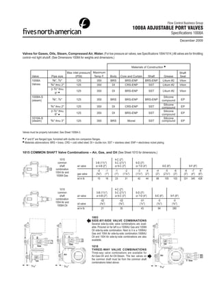
- 1. Flow Control Business Group 1008A ADJUSTABLE PORT VALVES Specifications 1008A December 2009 Valves for Gases, Oils, Steam, Compressed Air, Water. (For low pressure air valves, see Specifications 1004/1014.) All valves are for throttling control--not tight shutoff. (See Dimensions 1008A for weights and dimensions.) Materials of Construction Max inlet pressure Maximum Shaft Valve Pipe size (PSI) Temp F. Body Core and Curtain Shaft Grease Seal 1008A 3⁄8", ½" 125 350 BRS BRS-ENP BRS-ENP Litium #2 Viton Valves ¾" thru 2" 125 350 DI CRS-ENP SST Litium #2 Viton 2-½" thru 125 350 DI BRS-ENP SST Litium #2 Viton 6" 1008A-S Silicone (steam) 3⁄8", ½" 125 350 BRS BRS-ENP BRS-ENP compound EP Silicone ¾" thru 2" 125 350 DI CRS-ENP SST compound EP 2-½" thru Silicone 6" 125 350 DI BRS-ENP SST compound EP 1010A-S Silicone (steam) ¾" thru 3" 125 350 BRS Monel SST compound EP Valves must be properly lubricated. See Sheet 1008A-3. 4" and 6" are flanged type, furnished with ductile iron companion flanges. Materials abbreviations: BRS = brass, CRS = cold rolled steel, DI = ductile iron, SST = stainless steel, ENP = electroless nickel plating. 1015 COMMON SHAFT Valve Combinations – Air, Gas, and Oil (See Sheet 1015 for dimensions.) 1015 4-C (2") common 3-B (1½") 5-C (2½") 6-D (3") shaft air valve or 4-B (2") or 6-C (3") or 7-D (4") 8-E (6") 9-F (8") combination -0 -1 -1 -2 -3 -4 -4 -5 -6 -6 -7 -8 1004 Air and gas valve (3⁄8") (1") (1") (1¼") (1½") (2") (2") (2½") (3") (3") (4") (6") 1008A Gas wt in lb 15 16 23 31 42 44 88 105 103 331 345 428 1015 4-C (2") common 3-B (1½") 5-C (2½") 6-D (3") shaft air valve or 4-B (2") or 6-C (3") or 7-D (4") 8-E (6") 9-F (8") combination -02 -02 -01 -0 -0 1004 Air and oil valve (3⁄8") (3⁄8") (½") (¾") (¾") 1008A Oil wt in lb 21 35 43 94 280 1003 SIDE-BY-SIDE VALVE COMBINATIONS Several side-by-side valve combinations are avail- able. Pictured on far left is a 1008AU Gas and 1008A Oil side-by-side combination. Next to it is a 1008AU Gas and 1004 Air side-by-side combination.1008AU Oil and 1004 Air side-by-side combinations are also available. Gas Oil Gas 1018 THREE-WAY VALVE COMBINATIONS Three-way valve combinations are available for Air Air Air-Gas-Oil and Air-Oil-Steam. The two valves on the common shaft must be from the common shaft Gas Oil combinations listed above. 9⁄16" 9⁄16" 9⁄16"
- 2. SELECTION Fluid Pressure Valve Refer to Air 0-3 psig 1004, 1014 Specifications 1004/1014 0-125 psig 1008A Sheet 1008A-1 and example below Gas, Oil 0-125 psig 1008A Capacities 1008A Water Sheet 1008A-1 and example below Steam (saturated) 0-125 psig 1008A-S Capacities 1008A 1010A-S Sheet 1008A-1 and examples below SIZING Air, 3-125 psig. Subtract desired high flow pressure drop from absolute psia ÷ (35 + 15) psia = 0.8. Use Chart A. Density correction factor for 50 psia upstream of the valve to get absolute pressure downstream of the valve. upstream pressure is 0.53 (from inset, Chart A). Corrected flow is 1225 scfm × Divide this by upstream absolute pressure. If the result is 0.7 or more, refer to 0.53 = 650 cfm. First diagonal line above intersection of 10 psi pressure drop Chart A of Sheet 1008A-1. Multiply the desired maximum air flow, scfm, by the and 650 cfm lines on Chart A represents a 2" valve. appropriate density correction factor from the inset on Chart A, and locate the intersection of lines corresponding to corrected flow and pressure drop. The Gas, 2 psig and up. Follow the same procedure as with 3-125 psig air, first diagonal line above this point indicates the correct valve size. If the ratio of using Chart A for absolute pressure ratios of 0.7 and higher and Chart B for downstream absolute pressure to upstream absolute pressure is 0.69 or less, ratio of 0.69 or less. In either case, multiply flow, scfm, by the appropriate gas read the intersection, on Chart B, of lines corresponding to upstream absolute gravity correction factor from the two-line table across the top of the inset on pressure and flow, scfm (do not multiply by the density correction factor). The Chart A. first diagonal line above this point represents the correct size valve. Steam (saturated), up to 125 psig. (Specify "-S" model.) When ratio of downstream absolute pressure to upstream absolute pressure is 0.7 or greater, Example: Select a valve to control 1225 scfm air in a 35 psig line. Maximum pres- use same selection method as with 3-125 psig air, but select valve from Chart sure drop across the wide open valve should be 10 psi. Pressure downstream C. When pressure ratio is 0.69 or less, follow procedure for 3-125 psig air, but of the valve will be (35 – 10) = 25 psig. Ratio of absolute pressures is (25 + 15) select valve from Chart D. HOW TO ORDER Code for Valve pipe size Options 1008A-_-_ Standard Valve 1008AU-_-_ Valve with optional U bracket (for side by side combo) 1010A-_-_ Brass and Monel construction (for steam or oxygen* service) -02 3⁄8 -01 ½ -0 ¾ -1 1 -2 1¼ -3 1½ -4 2 -5 2½ -6 3 -7 4 -8 6 blank no option -R reverse acting -S steam service -L NEMA 4 low fire switch -LD manual locking device -LDL manual locking device and NEMA 4 low fire switch -C Cleaned for oxygen service *see Bulletin 1010A-C/1008A-C Examples: 1008A-3-R 1½" adjustable port valve reverse acting 1008AU-4-LDL 2" adjustable port valve with U bracket manual locking device and low fire switch 1008A-8 6" adjustable port valve *See Bulletin 1010A-C/1008A-C for oxygen service. Page 2 Specifications 1008A
- 3. Specifications 1008A Page 3 1020 Designates any single valve/operator combination that Fives North American is to ship assembled, regardless of whether FNA sold the operator along with the valve or the customer supplied the operator for FNA to mount. Example: 1020 Valve combination consisting of 1008A-4 Valve with B & L and M940 Operator mounted. 1021 Designates any single valve that Fives North American is to ship with bracket and linkage only assembled without an actuator. 1003 Side-by-Side Valve Combinations – Valve combinations are entered in the following order: 1. Fuel valve 2. Air valve or second fuel valve 3. Air valve 4. Bracket and linkage for customer's control motor, or operator that Fives North American is to supply and mount. Any other modifications of the linkage are also noted here. The operator is normally mounted on the fuel valve, usually an adjustable port valve with "U" bracket. Quantity Part Number Description Example 1 1003 Side-by-Side Valve Combination consisting of: 1008A-4 Valve w/ 1004-6-C Valve w/ B & L for M940 1015 Common Shaft Valve Combinations – Order write-up procedure: 1015 - 04B3 - 02 Common Shaft Valve Combination with B & L and 1008A valve size air valve size where 04 or 14 = air APV valve type B = valve body size 3 = Fives North American pipe code Indicates common shaft APV combination 1018 Three-Way Valve Combinations Quantity Part Number Description Example 1 1018 Three-Way Valve Combination consisting of: 1015 Common Shaft Valve Combination consisting of: 1008A-3 Valve w/ 1004-6-D Valve mounted side-by-side to 1008A-01 Valve w/ B & L for M940 WARNING: Situations dangerous to personnel and property may exist with the operation and maintenance of any combustion equipment. The presence of fuels, oxidants, hot and cold combustion products, hot surfaces, electrical power in control and ignition circuits, etc., are inherent with any combustion application. Parts of this product may exceed 160F in operation and present a contact hazard. Fives North American Combustion, Inc. urges compliance with National Safety Standards and insurance Underwriters recommendations, and care in operation. Fives North American Combustion, Inc. - 4455 East 71st Street - Cleveland, OH 44105 USA - Phone 216.271.6000 Fax 216.641.7852 - email: fna.sales@fivesgroup.com - www.fivesgroup.com/fivesna FNA 12-09-Specs1008A