SlideShare a Scribd company logo
1 of 35
Download to read offline
1998-99 ENGINES
2.4L 4-Cylinder
ENGINE IDENTIFICATION
Vehicle Identification Number (VIN) is stamped on a metal tab, attached to top left end of instrument panel,
near the windshield. Engine can also be identified by an engine code (3rd character) stamped on left side of
cylinder block. See Fig. 1 . See the ENGINE IDENTIFICATION CODES table.
ENGINE IDENTIFICATION CODES
Fig. 1: Locating Partial VIN & Engine Code
Courtesy of GENERAL MOTORS CORP.
ADJUSTMENTS
VALVE CLEARANCE ADJUSTMENT
NOTE: For repair procedures not covered in this article, see ENGINE OVERHAUL
PROCEDURES article in GENERAL INFORMATION.
Application VIN Code Engine ID
2.4L DOHC SFI T LD9
1999 Pontiac Grand Am GT
1998-99 ENGINES 2.4L 4-Cylinder
1999 Pontiac Grand Am GT
1998-99 ENGINES 2.4L 4-Cylinder
me
Wednesday, May 20, 2009 9:20:38 AM Page 1 © 2005 Mitchell Repair Information Company, LLC.
me
Wednesday, May 20, 2009 9:21:20 AM Page 1 © 2005 Mitchell Repair Information Company, LLC.
Engine is equipped with non-adjustable hydraulic valve lifters.
TROUBLE SHOOTING
REMOVAL & INSTALLATION
FUEL PRESSURE RELEASE
Disconnect negative battery cable. Loosen fuel filler cap. Install Fuel Pressure Gauge (J-34730-1) on fuel
pressure connector of fuel rail. Wrap shop towel around pressure connection when installing fuel pressure gauge
to absorb fuel leakage. Install gauge bleed hose into container. Open bleed valve to bleed fuel pressure.
COOLING SYSTEM BLEEDING
1. Fill radiator and surge tank to base of filler neck. Install pressure cap on surge tank. Block drive wheels
and firmly apply parking brake. Shift automatic transaxle to Park or manual transaxle to Neutral. Start
engine. Run until upper radiator hose is hot. Stop engine.
2. Observe coolant level in surge tank or radiator. If not above FULL mark, allow engine to cool and then
remove surge tank cap. Add coolant. If low coolant light lights after servicing, remove surge tank cap and
add coolant to bring level to COLD FULL mark when system is cold.
ENGINE
Removal (1998 Models)
1. Release fuel pressure. See FUEL PRESSURE RELEASE . Disconnect negative battery cable. Drain
cooling system. Discharge air conditioning system (if equipped) using approved refrigerant
NOTE: To trouble shoot mechanical engine components, see ENGINE MECHANICAL in
GENERAL TROUBLE SHOOTING article in GENERAL INFORMATION.
CAUTION: When battery is disconnected, vehicle computer and memory systems
may lose memory data. Driveability problems may exist until computer
systems have completed a relearn cycle. For 1998, see appropriate model
under COMPUTER RELEARN PROCEDURES in COMPUTER RELEARN
PROCEDURES article in GENERAL INFORMATION. For 1999, See
appropriate model in COMPUTER RELEARN PROCEDURES article in
GENERAL INFORMATION.
NOTE: For reassembly reference, label all electrical connectors, vacuum hoses and
fuel lines before removal. Also place mating marks on engine hood and other
major assemblies before removal.
NOTE: On 1998 models, remove engine and transaxle as an assembly through bottom
of engine compartment.
1999 Pontiac Grand Am GT
1998-99 ENGINES 2.4L 4-Cylinder
me
Wednesday, May 20, 2009 9:20:38 AM Page 2 © 2005 Mitchell Repair Information Company, LLC.
recovery/recycling equipment.
2. Remove left sound insulator and disconnect push rod from clutch pedal assembly (if equipped).
Disconnect control cables, coolant hoses, electrical connectors, vacuum hoses, and fuel lines as necessary.
Remove air cleaner assembly. Remove cooling fan. Disconnect air conditioning hose assembly from
compressor (if equipped). Discard "O" rings.
3. Remove throttle cable and bracket. Remove power steering pump bolts and pump (leave hoses
connected). Disconnect shift cables. Disconnect clutch actuator (slave cylinder) hydraulic line. Remove
exhaust manifold and heat shield. See EXHAUST MANIFOLD .
4. Support engine from above with Engine Support Fixture (J-28467-A). Remove coolant recovery tank
(leave hoses connected) and position aside. Remove engine mount from timing chain end of engine. Raise
and support vehicle. Remove front wheels. Remove right splash shield. Remove engine mount strut and
transaxle mount. Separate ball joints from steering knuckles.
5. Put a suitable supporting device under suspension support, crossmember and stabilizer shaft. Remove
suspension support and stabilizer shaft. Remove heater outlet hose from radiator outlet pipe. Remove axle
shaft from transaxle and intermediate shaft (manual transaxle only) and position aside.
6. Remove flywheel housing cover. Put a suitable supporting device under engine and transaxle assembly
and lower vehicle onto support. Mark threads on engine upper support fixture hooks for installation
reference. Remove engine upper support fixture hooks. Raise vehicle slowly from engine and transaxle
assembly. Separate engine from transaxle (note bolt location for reassembly reference).
Installation
1. Assemble engine to transaxle, ensuring bolts are in correct locations. On automatic transaxle models,
clean torque converter bolts and bolt holes. Apply sealant to bolts. On all models, position engine and
transaxle assembly under engine compartment. Lower vehicle until transaxle mount is aligned. Install
transaxle mount bolt.
2. Install Engine Support Fixture (J-28467-A) above engine, adjusting it to previous setting. Install engine
mount at timing chain end of engine. Install engine mount at transaxle. Raise vehicle. Remove supporting
device from below engine and transaxle assembly. Install axle shafts.
3. Install suspension support, crossmember and stabilizer shaft assembly. Tighten suspension support rear
bolts, center bolts and then front bolts to specification. See TORQUE SPECIFICATIONS table.
Connect ball joints. Install engine mount strut. To complete installation, reverse removal procedure.
Evacuate and charge air conditioning system. Fill cooling system and crankcase.
Removal (1999 Models)
1. Release fuel pressure. See FUEL PRESSURE RELEASE . Disconnect negative battery cable. Drain
cooling system and engine oil. Remove fuel rail assembly, air intake duct from air cleaner, ignition coil
and module assembly. Disconnect control cables, coolant hoses, electrical connectors, vacuum hoses, and
fuel lines as necessary.
2. Unbolt power steering pump and secure aside. Remove air intake duct bracket. Remove cruise control
assembly and set aside. Install J 28467-360 engine support fixture. Remove fan belt and engine mount
assembly. Raise engine using support fixture, then remove engine mount bracket.
NOTE: On 1999 models, remove engine while leaving transmission in vehicle.
1999 Pontiac Grand Am GT
1998-99 ENGINES 2.4L 4-Cylinder
me
Wednesday, May 20, 2009 9:20:38 AM Page 3 © 2005 Mitchell Repair Information Company, LLC.
3. Raise and support vehicle. Remove front wheels and right splash shield. Remove crankshaft balancer.
Remove torque converter bolts and oxygen sensor. Lower vehicle. Remove generator and starter. Remove
exhaust brace bolt and exhaust manifold heat shield. Disconnect exhaust pipe from exhaust manifold.
4. Unbolt A/C compressor and secure aside. Remove oil pan-to-bellhousing bolts. Remove transmission
mount. Remove transmission-to-engine bolts. Install engine hoist, then remove engine while supporting
transaxle.
Installation
To install, reverse removal procedure. Tighten all fasteners to specifications. See TORQUE
SPECIFICATIONS table. Fill engine fluids, and bleed cooling system. See COOLING SYSTEM
BLEEDING .
INTAKE MANIFOLD
Removal
1. Disconnect negative battery cable. Disconnect electrical connectors and vacuum hoses from intake
manifold components as necessary. Disconnect air intake tube. Remove throttle cable bracket.
2. Remove generator mount bolt. Remove EGR pipe from EGR adapter. Remove intake manifold nuts and
bolts. Remove intake manifold and gasket.
Installation
Tighten all intake manifold nuts and bolts to specification in sequence. See Fig. 2 . See TORQUE
SPECIFICATIONS table. To complete installation, reverse removal procedure.
WARNING: Never remove intake manifold while engine is hot. Intake manifold is
made of composite plastic and can be damaged if removed while engine
is hot.
NOTE: Intake manifold gasket is reusable unless damaged. Numbered side of intake
manifold gasket must face intake manifold.
1999 Pontiac Grand Am GT
1998-99 ENGINES 2.4L 4-Cylinder
me
Wednesday, May 20, 2009 9:20:38 AM Page 4 © 2005 Mitchell Repair Information Company, LLC.
Fig. 2: Intake Manifold Tightening Sequence
Courtesy of GENERAL MOTORS CORP.
EXHAUST MANIFOLD
Removal
1. Disconnect negative battery cable. Disconnect oxygen sensor connector. Raise and support vehicle.
Remove exhaust manifold brace bolt. Remove upper heat shield. Disconnect exhaust pipe flex decoupler
from manifold. DO NOT allow flex decoupler to bend more than 3 degrees in any direction, as damage
will result.
2. Pull down and back on exhaust pipe to disengage it from manifold. Lower vehicle. Remove exhaust
manifold nuts. Remove exhaust manifold, seals and gaskets.
Installation
To install, reverse removal procedure using NEW gaskets. Tighten bolts to specification in sequence. See
TORQUE SPECIFICATIONS table. See Fig. 3 . If oxygen sensor was removed, coat threads with Anti-Seize
Compound (5612695) before installation.
1999 Pontiac Grand Am GT
1998-99 ENGINES 2.4L 4-Cylinder
me
Wednesday, May 20, 2009 9:20:39 AM Page 5 © 2005 Mitchell Repair Information Company, LLC.
Fig. 3: Exhaust Manifold Tightening Sequence
Courtesy of GENERAL MOTORS CORP.
CYLINDER HEAD
Removal
1. Disconnect negative battery cable. Drain cooling system. Remove throttle body-to-air cleaner duct.
Disconnect heater hose and throttle body hose from water outlet. Remove power brake vacuum hose from
throttle body.
2. Disconnect electrical connectors, vacuum hoses, and coolant hoses as necessary. Remove generator
mount bolt. Remove intake manifold. See INTAKE MANIFOLD . Remove generator mount bolt.
3. Reinstall generator mount bolt. Install Engine Support Fixtures (J-28467-400 and J-28467-A). Remove
exhaust manifold. See EXHAUST MANIFOLD . Remove ignition coil and module assembly
connectors. Remove attaching bolts and remove coil assembly from camshaft housing by pulling it
straight up. See Fig. 12 .
4. Disconnect camshaft position sensor connector. Remove power steering pump. Remove fuel line
retaining clamp from bracket on top of intake camshaft housing. Remove fuel rail from cylinder head, and
leaving fuel lines attached, position on top of master cylinder. Cover injector openings in head and
injector nozzles.
5. Remove timing chain and sprocket. See TIMING CHAIN, SPROCKETS & TENSIONER .
CAUTION: Turn camshaft housing upside down immediately after removing
from vehicle, or valve lifters will fall out and may be damaged.
1999 Pontiac Grand Am GT
1998-99 ENGINES 2.4L 4-Cylinder
me
Wednesday, May 20, 2009 9:20:39 AM Page 6 © 2005 Mitchell Repair Information Company, LLC.
Disconnect timing chain housing at intake camshaft housing but DO NOT remove from vehicle. Remove
bolts attaching intake camshaft housing to cylinder head bolts in reverse of tightening sequence. See Fig.
13 . Remove camshaft housing. Repeat procedure with exhaust camshaft housing.
6. Disconnect radiator inlet hose from coolant outlet and disconnect coolant temperature sensor connectors.
Remove cylinder head bolts in reverse order of tightening sequence. See Fig. 4 . Remove cylinder head
and gasket. See CYLINDER HEAD under OVERHAUL.
Installation
Clean threads of cylinder head bolts and bolt holes. Lightly coat bolt threads with engine oil. Install NEW
gasket, ensuring all holes are aligned with cylinder block. Install cylinder head and tighten cylinder head bolts
to specification in sequence. See TORQUE SPECIFICATIONS table. To complete installation, reverse
removal procedure. See Fig. 4 .
Fig. 4: Cylinder Head Bolt Tightening Sequence
Courtesy of GENERAL MOTORS CORP.
FRONT COVER
CAUTION: DO NOT use a thread tap to clean cylinder head bolt holes. Remove all
fluids from bolt holes.
1999 Pontiac Grand Am GT
1998-99 ENGINES 2.4L 4-Cylinder
me
Wednesday, May 20, 2009 9:20:39 AM Page 7 © 2005 Mitchell Repair Information Company, LLC.
Removal
1. Disconnect negative battery cable. Drain cooling system. Remove coolant recovery tank. Remove
serpentine drive belt. Remove generator (leave wiring attached). Attach Engine Support Fixture (J-28467-
400 and J-28467-A) to engine and generator stud. Remove bolts from upper half of front cover.
2. Remove engine mount assembly from timing chain end of engine. Remove engine mounting bracket
adapter. Raise and support vehicle. Remove right front wheel and splash shield. Remove crankshaft
balancer bolt. Remove crankshaft balancer with a puller. Remove lower bolts from front cover. Lower
vehicle. Remove front cover and gaskets.
Installation
To install, reverse removal procedure. Cover gasket is reusable if not damaged. Lubricate front seal with grease
before installing crankshaft balancer. To complete installation, reverse removal procedure. Tighten nuts and
bolts to specification. See TORQUE SPECIFICATIONS table. Fill cooling system.
CRANKSHAFT FRONT SEAL
Removal & Installation
Disconnect negative battery cable. Remove front cover. See FRONT COVER . Support cover, and drive seal
through rear of cover. Take care not to damage cover. Note direction of seal installation. To install seal, use
Seal Installer (J-36010).
TIMING CHAIN, SPROCKETS & TENSIONER
Removal
1. Disconnect negative battery cable. Remove front cover. See FRONT COVER . See Fig. 5 . Rotate
crankshaft in normal direction of rotation (clockwise, as viewed from front of engine) until cylinder No. 1
is at TDC of compression stroke.
2. The camshaft sprocket dowel pin hole should line up with holes on timing chain housing. The crankshaft
sprocket keyway should point upwards. See Fig. 5 . Remove timing chain guides. Raise and support
vehicle. Ensure slack in chain is above tensioner assembly, then remove chain tensioner.
3. Note that timing chain must be disengaged from any wear grooves in tensioner shoe before removing
shoe. Slide a screwdriver blade between chain and tensioner shoe, while pulling shoe outward (this
should disengage chain from wear grooves in shoe). If timing chain is not difficult to remove, go to step
5 . If it is difficult to remove timing chain shoe, go to next step.
NOTE: This procedure has been revised due to GM service manual update (SMU) # 00-
06-01-002 dated Feb, 2000
CAUTION: To prevent severe engine damage, carefully follow procedure.
1999 Pontiac Grand Am GT
1998-99 ENGINES 2.4L 4-Cylinder
me
Wednesday, May 20, 2009 9:20:39 AM Page 8 © 2005 Mitchell Repair Information Company, LLC.
4. Lower vehicle. Hold intake camshaft sprocket with Sprocket Wrench (J-39579) and remove sprocket bolt.
Remove washer from bolt and rethread bolt into camshaft by hand. Remove camshaft sprocket using a 3-
jaw puller. DO NOT attempt to pry sprocket off or damage will result.
5. Remove tensioner assembly bolts and tensioner. Mark outer surface of timing chain and crankshaft
sprocket for reassembly reference. Remove timing chain.
Fig. 5: Assembled View Of Timing Chain, Sprockets & Tensioner
Courtesy of GENERAL MOTORS CORP.
Installation
CAUTION: To prevent damage to sprocket or timing chain housing, use a puller
to remove sprocket from camshaft. DO NOT pry sprocket from
camshaft.
1999 Pontiac Grand Am GT
1998-99 ENGINES 2.4L 4-Cylinder
me
Wednesday, May 20, 2009 9:20:39 AM Page 9 © 2005 Mitchell Repair Information Company, LLC.
1. Install the camshaft sprockets. The sprockets are identical and interchangeable. Clean the old sealer off of
the bolts with a wire brush. Clean the threaded hole in the camshaft with a nylon bristle brush. Coat the
camshaft bolts with Adhesive/Sealant Compound (GM 1234593) or equivalent. See Fig. 6 .
2. Install the camshaft sprocket bolts and washers while holding the sprockets with Tool (J- 39579). Tighten
the bolts to 52 ft. lbs. (70 N.m).
3. Install Tool (J-36008-A) through the holes in the camshaft sprockets and into the holes in the timing
chain housing. This will position the camshaft for correct timing. Use the following steps if the camshafts
are out of position and must be rotated more than 1/8 turn in order to install the alignment dowel pins:
A. The crankshaft must be rotated 90 degrees clockwise from TDC to give the valves adequate
clearance to open.
B. Once the camshafts are in position and the dowels are installed, rotate the crankshaft counter
clockwise back to TDC.
4. Install the timing chain over the exhaust camshaft sprocket around the coolant pump sprocket and around
the crankshaft sprocket. Remove the alignment dowel pin from the intake camshaft. Use Tool (J-39579)
in order to rotate the intake camshaft sprocket counter clockwise enough to allow the timing chain to slide
over the intake camshaft sprocket. Release Tool (J-39579). The length of the chain between the two
camshaft sprockets will tighten.
5. If properly timed, the intake camshaft alignment dowel pin will slide in easily. If the dowel pin does not
fully index, the camshafts are not timed correctly and the procedure must be repeated. Leave the
alignment dowel pins installed. The keyway on the crankshaft and the mark on the cylinder block should
be aligned when the slack is removed from the chain between the intake camshaft sprocket and the
crankshaft sprocket. If the mark and the keyway are not aligned, move the chain one tooth forward or
rearward. Remove the slack and recheck the marks.
NOTE: Ensure camshaft sprocket alignment pins are in the cylinder block and the
timing chain housing, prior to installing the timing chain housing. The
camshaft sprocket alignment pins ensure proper chain housing and front
cover location for correct front oil seal to crankshaft alignment.
CAUTION: DO NOT rotate the crankshaft clockwise to TDC. Valve or piston
damage could occur. The timing chain and crankshaft sprocket must
be put in a specific direction for chain noise and wear
considerations. The surfaces that were marked during removal
should be showing when the chain and crankshaft sprocket are
installed.
NOTE: Use the following steps in order to reset the timing chain tensioner
assembly to the zero position:
A. Reset the timing chain tensioner assembly.
B. Insert the tensioner plunger assembly into the tensioner housing.
C. With the tensioner plunger fully extended, turn the complete
1999 Pontiac Grand Am GT
1998-99 ENGINES 2.4L 4-Cylinder
me
Wednesday, May 20, 2009 9:20:39 AM Page 10 © 2005 Mitchell Repair Information Company, LLC.
6. Check the plunger to ensure the plunger is out of the cylinder at the correct dimension. The correct
dimension for the plunger to extend out of the cylinder is .070" (1.7 mm) maximum. See Fig. 8 . Loosely
install the tensioner assembly and bolts to the timing chain housing. See Fig. 9 . Install the timing chain
tensioner shoe on the stud. Apply hand pressure to the timing chain tensioner shoe until the locking tab
seats in the groove in the stud. Tighten the timing chain tensioner bolts. DO NOT over tighten. Tighten
the bolts to 89 INCH lbs. (10 N.m).
7. Release the timing chain tensioner plunger using the following procedure:
A. Using a flat blade screwdriver, cotter pin remover, or a similar tool, press firmly against the face of
the timing chain tensioner plunger. See Fig. 10 .
B. Depress the timing chain tensioner plunger until the plunger is bottomed out in the bore of the
timing chain tensioner. See Fig. 8 .
C. Release the tensioner plunger. See Fig. 10 . The plunger should press firmly against the back of the
timing chain tensioner shoe. Remove Tool (J- 36008-A) from the camshaft sprockets.
8. Rotate the crankshaft clockwise two full rotations. Align the crankshaft keyway with the mark on the
cylinder block and reinstall the alignment dowel pins. The alignment dowel pins will slide in easily if the
engine is timed correctly. Install the timing chain guides.
assembly upside down on a bench or other flat surface. See Fig. 7 .
D. With the plunger face against the workbench, press firmly on the
bottom of the tensioner housing.
E. Compress the plunger until the plunger is seated flush in the
tensioner. See Fig. 8 .
CAUTION: If the timing chain tensioner plunger is not released from the
installation position, engine damage will occur when the engine is
started.
NOTE: If the timing chain tensioner plunger cannot be depressed, the
plunger is not properly reset and the procedure for resetting the
timing chain tensioner should be repeated.
CAUTION: Beginning with the 1998 model year, the timing chain on the LD9 (VIN
T) Twin Cam Engine is different from the chain found on earlier
versions of this engine, and is not to be replaced with a timing chain
from earlier model year engines. The timing sprockets were also
changed beginning in 1998, and the shape of the chain links matches
the sprockets. Engine damage may result if the wrong timing chain is
used. The timing chain and the crankshaft sprocket must be marked
so that they are reinstalled in the same side facing out at the time of
assembly.
1999 Pontiac Grand Am GT
1998-99 ENGINES 2.4L 4-Cylinder
me
Wednesday, May 20, 2009 9:20:39 AM Page 11 © 2005 Mitchell Repair Information Company, LLC.
Fig. 6: Installing Timing Chain Sprockets
Courtesy of GENERAL MOTORS CORP.
1999 Pontiac Grand Am GT
1998-99 ENGINES 2.4L 4-Cylinder
me
Wednesday, May 20, 2009 9:20:39 AM Page 12 © 2005 Mitchell Repair Information Company, LLC.
Fig. 7: Released View Of Timing Chain Tensioner Assembly
Courtesy of GENERAL MOTORS CORP.
1999 Pontiac Grand Am GT
1998-99 ENGINES 2.4L 4-Cylinder
me
Wednesday, May 20, 2009 9:20:39 AM Page 13 © 2005 Mitchell Repair Information Company, LLC.
Fig. 8: Compressed View Of Timing Chain Tensioner Assembly
Courtesy of GENERAL MOTORS CORP.
1999 Pontiac Grand Am GT
1998-99 ENGINES 2.4L 4-Cylinder
me
Wednesday, May 20, 2009 9:20:39 AM Page 14 © 2005 Mitchell Repair Information Company, LLC.
Fig. 9: Installing Shoe & Timing Chain Tensioner Assembly
Courtesy of GENERAL MOTORS CORP.
1999 Pontiac Grand Am GT
1998-99 ENGINES 2.4L 4-Cylinder
me
Wednesday, May 20, 2009 9:20:39 AM Page 15 © 2005 Mitchell Repair Information Company, LLC.
Fig. 10: Releasing Timing Chain Tensioner Assembly
Courtesy of GENERAL MOTORS CORP.
TIMING CHAIN HOUSING
1999 Pontiac Grand Am GT
1998-99 ENGINES 2.4L 4-Cylinder
me
Wednesday, May 20, 2009 9:20:39 AM Page 16 © 2005 Mitchell Repair Information Company, LLC.
Removal
1. Disconnect negative battery cable. Remove front cover. See FRONT COVER . Raise and support
vehicle. Drain cooling system by disconnecting heater hose from thermostat housing. Remove nuts
securing water pump to timing chain housing. Remove timing chain and tensioner, making sure to mark
chain and sprocket outside surfaces. See TIMING CHAIN, SPROCKETS & TENSIONER .
2. Remove fasteners attaching timing chain housing to block. Remove 4 bolts securing oil pan to front
cover. Remove stud from lowest point on timing chain housing (if left installed, stud prevents removal of
housing).
3. Lower vehicle. Hold camshaft sprockets with Sprocket Wrench (J-39579) and remove sprocket bolts.
Remove bolts securing timing chain housing to camshaft housings. Remove timing chain housing and
gaskets (if necessary, raise engine slightly from above).
4. If necessary, remove timing chain idler sprocket and bearing. See TIMING CHAIN IDLER
SPROCKET & BEARING .
Installation
1. Replace oil pan gasket if damaged. If silicone bead at corner joints is damaged, repair it by applying just
enough Silicone Sealant (12345739) to restore it to its original dimension (too much sealant may cause
part misalignment, resulting in oil leaks).
2. Ensure dowel pins are installed in cylinder block. Install timing chain housing with NEW gaskets
(without sealer). Install and hand-tighten all timing chain housing bolts, then tighten to specification. See
TORQUE SPECIFICATIONS table. To install remaining components, reverse removal procedure. Fill
cooling system.
TIMING CHAIN IDLER SPROCKET & BEARING
Removal
1. Remove timing chain housing. See TIMING CHAIN HOUSING . Remove snap ring securing bearing
in housing. See Fig. 11 . Install Remover/Installer Plate (J-36998-4) on front side of housing, engaging
alignment pins into bolt holes in housing.
2. Using Handle (J-36998-2), press sprocket out of bearing. Reposition remover/installer plate onto rear side
of housing, engaging water pump studs into holes in plate. Using Remover/Installer (J-36998-1) and
Handle (J-36998-2), press bearing out of housing.
Installation
Clean snap ring groove in housing. Coat surfaces of housing and NEW bearing with Sealant (12345493). Install
remover/installer plate on front side of housing. Using remover/installer and handle, press bearing into housing.
NOTE: Timing chain housing does not need to be completely removed if replacing
gasket between cylinder head or cylinder block and timing chain housing.
NOTE: Replace bearing whenever idler sprocket is removed.
1999 Pontiac Grand Am GT
1998-99 ENGINES 2.4L 4-Cylinder
me
Wednesday, May 20, 2009 9:20:39 AM Page 17 © 2005 Mitchell Repair Information Company, LLC.
Reposition remover/installer plate to rear side of housing. Using remover/installer and handle, press idler
sprocket through bearing. Install bearing snap ring. Install timing chain housing. See TIMING CHAIN
HOUSING .
Fig. 11: Exploded View Of Timing Chain Idler Sprocket Assembly
Courtesy of GENERAL MOTORS CORP.
INTAKE CAMSHAFT & HOUSING
Removal
1. Disconnect negative battery cable. Disconnect ignition coil electrical connector. Remove bolts, and
remove ignition coil and module assembly by pulling it straight up. See Fig. 12 . It may be necessary to
use Spark Plug Wire Remover (J-36011) to break plug wire connectors loose by twisting and then
pulling.
2. Disconnect camshaft position sensor connector. Remove power steering pump and set aside (leave hoses
connected). Disconnect vacuum line from fuel pressure regulator. Disconnect fuel injector harness
connector. Remove fuel line clamp from top of intake camshaft housing. Remove fuel rail bolts.
3. Remove fuel rail (leave fuel lines attached). Cover injector openings in cylinder head. Cover injector
nozzles. Remove timing chain and camshaft sprockets. See TIMING CHAIN, SPROCKETS &
TENSIONER . Remove bolts securing timing chain housing to camshaft housing.
CAUTION: Any time camshaft housing bolts are loosened or removed, gasket
between camshaft housing and cylinder head must be replaced.
1999 Pontiac Grand Am GT
1998-99 ENGINES 2.4L 4-Cylinder
me
Wednesday, May 20, 2009 9:20:39 AM Page 18 © 2005 Mitchell Repair Information Company, LLC.
4. Remove bolts that secure camshaft housing cover to camshaft housing. Working in reverse order of
tightening sequence, evenly loosen and remove bolts securing camshaft housing to cylinder head (leave 2
bolts loosely in place to keep camshaft housing in place while separating cover from housing). See Fig.
13 .
5. Install 4 camshaft housing-to-cylinder head bolts into tapped holes in camshaft housing cover. Evenly
tighten bolts to separate cover from housing. Remove 2 loosely installed camshaft housing bolts. Remove
camshaft housing cover and seals.
6. Install and hand-tighten one camshaft housing bolt to keep camshaft housing in place while removing
camshaft and lifters. For installation reference, note position of dowel pin (on timing chain sprocket) in
relation to camshaft housing. Remove camshaft. Remove camshaft housing and lifters as an assembly. If
necessary, remove lifters from camshaft housing.
Inspection
If camshaft journal diameter, lobe lift, end play or oil clearance is not within specification, replace components
as necessary. See CAMSHAFT SPECIFICATIONS table under ENGINE SPECIFICATIONS. Check
camshaft housing. See CAMSHAFT HOUSING under OVERHAUL.
Installation
1. Ensure dowel pins aligning camshaft housing with cylinder head are installed. Install camshaft housing
with a NEW gasket (no sealant required). Loosely install one camshaft housing bolt to keep camshaft
housing in place while installing lifters and camshaft.
2. Coat lifters and camshaft with Prelube (12345501). Install lifters in their original locations. Install
camshaft, ensuring dowel pin on timing chain sprocket is in same position as when removed. Dowel pin
should point straight up and lined up with centerline of lifter bore. Install NEW Green camshaft housing
cover seals into cover (no sealant is required).
3. Remove bolt installed to keep camshaft housing in place. Apply GM Pipe Sealant (1052080) to threads of
bolts securing housing to cylinder head and cover to housing. Tighten camshaft housing bolts to
specification in sequence. See Fig. 13 . Note that bolts 11 and 12 have a different final torque than bolts
1-10. See TORQUE SPECIFICATIONS table.
4. Install timing chain housing and timing chain in reverse order of removal. Lubricate NEW "O" ring seals
with engine oil, and install them onto injectors. Install fuel rail. To install remaining components, reverse
removal procedure.
5. If a spark plug boot connector remained on a spark plug when ignition coil and module assembly was
removed, remove it from spark plug and install it onto ignition coil and module assembly. Set ignition
coil and module assembly in place and press straight down to install assembly onto spark plugs.
NOTE: If removing lifters, keep them in order; they must be installed in their
original locations. To prevent bleed-down, store lifters upside down in
clean engine oil.
NOTE: If replacing camshaft or lifters, add Engine Oil Supplement (1052367) to
crankcase. If camshaft is replaced, lifters must also be replaced.
1999 Pontiac Grand Am GT
1998-99 ENGINES 2.4L 4-Cylinder
me
Wednesday, May 20, 2009 9:20:39 AM Page 19 © 2005 Mitchell Repair Information Company, LLC.
6. Clean oil from threads of bolts securing assembly to camshaft housing. Apply GM Pipe Sealant
(1052080) to ignition coil-to-camshaft housing bolt threads. To complete installation, reverse removal
procedure.
Fig. 12: Camshaft Housing & Ignition Coil/Module Assembly
Courtesy of GENERAL MOTORS CORP.
1999 Pontiac Grand Am GT
1998-99 ENGINES 2.4L 4-Cylinder
me
Wednesday, May 20, 2009 9:20:39 AM Page 20 © 2005 Mitchell Repair Information Company, LLC.
Fig. 13: Camshaft Housing Bolt Tightening Sequence
Courtesy of GENERAL MOTORS CORP.
EXHAUST CAMSHAFT & HOUSING
Removal
1. Disconnect negative battery cable. Disconnect ignition coil electrical connector. Remove bolts, and
remove ignition coil and module assembly by pulling it straight up. See Fig. 12 . It may be necessary to
use Spark Plug Wire Remover (J-36011) to break plug wire connectors loose by twisting and then
pulling.
2. Disconnect oil pressure switch connector. Disconnect timing chain housing at exhaust camshaft housing
but DO NOT remove from vehicle. See TIMING CHAIN HOUSING . Remove exhaust camshaft cover
CAUTION: Any time camshaft housing bolts are loosened or removed, gasket
between camshaft housing and cylinder head must be replaced.
1999 Pontiac Grand Am GT
1998-99 ENGINES 2.4L 4-Cylinder
me
Wednesday, May 20, 2009 9:20:39 AM Page 21 © 2005 Mitchell Repair Information Company, LLC.
and gasket.
3. Working in reverse order of tightening sequence, evenly loosen and remove bolts securing camshaft
housing to cylinder head (leave 2 bolts loosely in place to keep camshaft housing in place while
separating cover from housing). See Fig. 13 . Install 4 camshaft housing-to-cylinder head bolts into
tapped holes in camshaft housing cover.
4. Evenly tighten bolts to separate cover from housing. Remove 2 loosely installed camshaft housing bolts.
Remove camshaft housing cover and seals.
5. Install and hand-tighten one camshaft housing bolt to keep camshaft housing in place while removing
camshaft and lifters. For installation reference, note position of dowel pin (on timing chain sprocket) in
relation to camshaft housing. Remove camshaft. Remove camshaft housing and lifters as an assembly. If
necessary, remove lifters from camshaft housing.
Inspection
If camshaft journal diameter, lobe lift, end play or oil clearance is not within specification, replace components
as necessary. See CAMSHAFT SPECIFICATIONS table under ENGINE SPECIFICATIONS. Check
camshaft housing. See CAMSHAFT HOUSING under OVERHAUL.
Installation
1. Ensure dowel pins aligning camshaft housing with cylinder head are installed. Install camshaft housing
with NEW gasket (no sealant required). Loosely install one camshaft housing bolt to keep camshaft
housing in place while installing lifters and camshaft.
2. Coat lifters and camshaft with Prelube (12345501). Install lifters in their original locations. Install
camshaft, ensuring dowel pin on timing chain sprocket is in same position as when removed. Dowel pin
should point straight up and lined up with centerline of lifter bore. Install NEW Orange seals into cover
(no sealant is required).
3. Remove bolt installed to keep camshaft housing in place. Apply GM Pipe Sealant (1052080) to threads of
bolts securing housing to cylinder head and cover to housing. Tighten camshaft housing bolts to
specification in sequence. See Fig. 13 . Note that bolts 11 and 12 have a different final torque than bolts
1-10. See TORQUE SPECIFICATIONS table.
4. Install timing chain housing and timing chain in reverse order of removal. To install remaining
components, reverse removal procedure. If a spark plug boot connector remained on a spark plug when
ignition coil and module assembly was removed, remove connector from spark plug and install it onto
ignition coil and module assembly.
5. Set ignition coil and module assembly in place and press straight down to install assembly onto spark
plugs. Clean oil from threads of bolts securing assembly to camshaft housing. Apply GM Pipe Sealant
NOTE: If removing lifters, keep them in order; they must be installed in their
original locations. To prevent bleed-down, store lifters upside down in
clean engine oil.
NOTE: If replacing camshaft or lifters, add Engine Oil Supplement (1052367) to
crankcase. If camshaft is replaced, lifters must also be replaced.
1999 Pontiac Grand Am GT
1998-99 ENGINES 2.4L 4-Cylinder
me
Wednesday, May 20, 2009 9:20:39 AM Page 22 © 2005 Mitchell Repair Information Company, LLC.
(1052080) to ignition coil-to-camshaft housing bolt threads. To complete installation, reverse removal
procedure.
CRANKSHAFT REAR OIL SEAL
Removal
1. Disconnect negative battery cable. Remove transaxle. For M/T, see appropriate article in CLUTCHES.
For A/T, see appropriate REMOVAL & INSTALLATION - A/T article in
TRANSAXLE/TRANSMISSIONS.
2. On manual transaxle models, mark pressure plate in relation to flywheel for installation reference.
Remove flexplate/flywheel assembly. Remove oil pan-to-seal housing bolts. Remove seal housing-to-
block bolts and gasket. See Fig. 25 .
3. Note direction of seal installation. Lay seal housing onto 2 wood blocks, with transaxle side of seal
housing facing down. To prevent seal housing damage, ensure wood blocks that seal housing are
supported across dowel pin and center bolt holes on both sides of seal opening. Using a small chisel in
seal relief grooves, evenly drive seal out of seal housing without scraping sealing surface.
Installation
1. Using Crankshaft Rear Seal Installer (J-36005), press NEW seal into housing. Replace oil pan gasket if
damaged. If silicone bead at corner joints is damaged, repair it by applying just enough Silicone Sealant
(12345739) to restore it to its original dimension (too much sealant may cause part misalignment,
resulting in oil leaks).
2. Set NEW seal housing-to-block gasket in place on dowel pins. Lubricate NEW seal lip with engine oil.
Install seal housing, but DO NOT install oil pan bolts. Tighten bolts securing seal housing to cylinder
block to specification. See TORQUE SPECIFICATIONS table. Install and tighten oil pan-to-seal
housing bolts to specification.
3. To install remaining components, reverse removal procedure. Apply Sealant (12345493) to
flexplate/flywheel bolts before installing them. Align reference marks on pressure plate and flywheel
(manual transmission).
OIL FLOW CHECK VALVE
Removal
1. Oil flow check valve is located below surface of cylinder block deck, near front of engine, and is
accessible with cylinder head removed. See Fig. 28 . Attach a slide hammer to check valve using Check
Valve Remover (J-38123) or a modified common 3/16 x 4" round-head machine screw. To modify screw,
grind 2 flat spots on outside diameter of screw head, parallel with screwdriver slot and 180 degrees across
from each other.
CAUTION: During check valve removal, DO NOT allow tool to impact ball at
bottom of check valve, as this may cause ball to dislodge. If check
ball is dislodged, it may fall into oil galley. Locate check ball if it is
missing.
1999 Pontiac Grand Am GT
1998-99 ENGINES 2.4L 4-Cylinder
me
Wednesday, May 20, 2009 9:20:39 AM Page 23 © 2005 Mitchell Repair Information Company, LLC.
2. Insert check valve remover (or modified machine screw) into check valve, then rotate tool 90 degrees so
it will lock into indentations in check valve. DO NOT allow tools to contact check ball as it can drop into
engine oil galleries. Pull check valve out of its bore.
Installation
If check ball is missing, it has dropped into oil galleries and must be retrieved before installation. Using slide
hammer and check valve remover (opposite end), or a hammer and drift punch, drive NEW check valve into its
bore until it is seated (normally, check valve will seat slightly below surface). A distinct change of sound will
result when check valve seats.
VALVE LIFTERS
Removal & Installation
To remove and install valve lifters, remove camshafts and camshaft housings. See INTAKE CAMSHAFT &
HOUSING . Also See EXHAUST CAMSHAFT & HOUSING .
RADIATOR (ACHIEVA, GRAND AM & SKYLARK)
Removal
1. Disconnect the negative battery cable
2. Drain the cooling system. Recover the coolant.
3. Remove the air intake duct assembly by removing the air cleaner outlet resonator mounting screws.
Disconnect the air cleaner outlet resonator clamp at throttle body. Remove the air cleaner outlet duct from
air cleaner outlet resonator and air cleaner assembly. Disconnect the crankcase vent hose from the air
cleaner outlet resonator. Remove the air cleaner outlet resonator.
4. Disconnect the upper transaxle oil cooler line from the radiator (Automatic Transmission).
5. Disconnect the radiator inlet hose and the clamp from the radiator
6. Raise the vehicle. See JACKING & HOISTING in SPECIFICATIONS & PROCEDURES article in
WHEEL ALIGNMENT.
CAUTION: Before servicing any electrical component, the ignition key must be in the
OFF or LOCK position and all electrical loads must be OFF, unless
instructed otherwise in these procedures. If a tool or equipment could
easily come in contact with a live exposed electrical terminal, also
disconnect the negative battery cable. Failure to follow these precautions
may cause personal injury and/or damage to the vehicle or its
components.
NOTE: When adding coolant, it is important that you use GM Goodwrench DEX-COOL
(tm) coolant. If coolant other than DEX-COOL(tm) is added to the system, the
engine coolant will require change sooner: at 30,000 miles (50 000 km) or 24
months.
1999 Pontiac Grand Am GT
1998-99 ENGINES 2.4L 4-Cylinder
me
Wednesday, May 20, 2009 9:20:39 AM Page 24 © 2005 Mitchell Repair Information Company, LLC.
7. Disconnect the lower transaxle oil cooler line from the radiator.
8. Remove the cooling fan by removing the cooling fan bracket bolt. Disconnect the wiring harness
connector from the fan motor. Remove the cooling fan assembly.
9. Remove the splash shield that is below the radiator outlet hose.
10. Disconnect the radiator outlet hose from the radiator.
11. Lower the vehicle.
12. Remove the retaining clip from the condenser line
13. Remove the condenser to radiator bolts.
14. Disconnect the surge tank inlet hose and the clamp from the radiator.
15. Remove the radiator retaining bolts and the mounts.
16. Remove the radiator.
Installation
1. Install the radiator
2. Install the radiator mounts and the bolts Tighten the bolts to 89 INCH lbs. (10 N.m).
3. Connect the surge tank inlet hose and the clamp to the radiator
4. Install the radiator to condenser bolts. Install the retaining clip to the condenser line.
5. Raise the vehicle.
6. Connect the radiator outlet hose and the clamp to the radiator.
7. Install the splash shield that is below the radiator outlet hose.
8. Install the cooling fan.
9. Connect the lower transaxle oil cooler line to the radiator (Automatic Transmission). Tighten the
transaxle oil cooler line fitting to 22 ft. lbs. (30 N.m).
10. Lower the vehicle.
11. Connect the radiator inlet hose and the clamp to the radiator.
12. Connect the upper transaxle oil cooler line to the radiator (Automatic Transmission). Tighten the
transaxle oil cooler line fitting to 22 ft. lbs. (30 N.m).
13. Connect the air intake duct assembly.
14. Fill the cooling system. Bleed cooling system and check for leaks. See COOLING SYSTEM
BLEEDING .
RADIATOR (ALERO)
NOTE: After servicing the cooling system, an intermittent low coolant lamp may
illuminate during extreme driving maneuvers. In order to eliminate this
condition, remove the surge tank cap and add coolant to a level at or
above the split line of the tank when the system is cold.
CAUTION: Before servicing any electrical component, the ignition key must be in the
1999 Pontiac Grand Am GT
1998-99 ENGINES 2.4L 4-Cylinder
me
Wednesday, May 20, 2009 9:20:39 AM Page 25 © 2005 Mitchell Repair Information Company, LLC.
Removal
1. Disconnect negative battery cable. Disconnect positive battery cable. Remove the retainer bolt and
retainer. Remove the battery and battery insulator from vehicle.
2. Remove the battery tray screws and the battery tray.
3. Evacuate the A/C system using approved recover and recycling procedures. See EVACUATING A/C
SYSTEM .
4. Drain the cooling system. Recover the coolant.
5. Remove the upper radiator hose.
6. Remove the upper transaxle cooler line.
7. Remove the coolant surge tank hose.
8. Remove the condenser inlet fitting from the discharge hose.
9. Disconnect the cooling fan electrical connection.
10. Raise the vehicle. See JACKING & HOISTING in SPECIFICATIONS & PROCEDURES article in
WHEEL ALIGNMENT.
11. Remove the lower closeout panel.
12. Remove the lower radiator hose from the radiator.
13. Remove the lower transaxle cooler line.
14. Remove the evaporator line from the condenser outlet.
15. Remove the lower radiator mounting panel.
16. Remove the radiator, fan and condenser as an assembly from the vehicle.
17. Remove the condenser from the radiator.
18. Remove the fan shroud from the radiator.
Installation
1. Install the fan shroud to the radiator.
2. Install the condenser to the radiator. Tighten the bolt to 44 INCH lbs. (5 N.m).
3. Install the radiator, fan, and condenser as an assembly to the vehicle.
OFF or LOCK position and all electrical loads must be OFF, unless
instructed otherwise in these procedures. If a tool or equipment could
easily come in contact with a live exposed electrical terminal, also
disconnect the negative battery cable. Failure to follow these precautions
may cause personal injury and/or damage to the vehicle or its
components.
NOTE: When adding coolant, it is important that you use GM Goodwrench DEX-COOL
(tm) coolant. If coolant other than DEX-COOL(tm) is added to the system, the
engine coolant will require change sooner: at 30,000 miles (50 000 km) or 24
months.
1999 Pontiac Grand Am GT
1998-99 ENGINES 2.4L 4-Cylinder
me
Wednesday, May 20, 2009 9:20:39 AM Page 26 © 2005 Mitchell Repair Information Company, LLC.
4. Install the lower radiator mounting panel. Tighten the bolts to 89 INCH lbs. (10 N.m)
5. Install the condenser outlet to the evaporator line. Tighten the bolt to 18 ft. lbs. (25 N.m).
6. Install the lower radiator hose to the radiator.
7. Install the lower closeout panel.
8. Lower the vehicle. Install the cooling fan electrical connection.
9. Install the lower transaxle cooler line. Tighten the bolt to 22 ft. lbs. (30 N.m).
10. Install the condenser inlet fitting to the discharge hose. Tighten the bolt to 18 ft. lbs. (25 N.m).
11. Install the coolant surge tank hose.
12. Install the upper transaxle cooler line. Tighten the bolt to 22 ft. lbs. (30 N.m).
13. Install the upper radiator hose.
14. Refill the cooling system.
15. Recharge the A/C system. See CHARGING A/C SYSTEM in GENERAL SERVICING article in
HEATING & AIR CONDITIONING.
16. Install the battery tray.
17. Install the battery.
18. Start engine. Bleed cooling system. See COOLING SYSTEM BLEEDING . Inspect the cooling system
for leaks.
RADIATOR (CAVALIER & SUNFIRE)
Removal
1. Disconnect the negative battery cable.
NOTE: After servicing the cooling system, and if the vehicle is equipped with an
intermittent low coolant light, an occasional low coolant light may be
encountered during some extreme driving maneuvers. This complaint should
be eliminated by removing the surge tank cap and adding coolant to a level just
at or above the full cold line when the system is cold.
CAUTION: Before servicing any electrical component, the ignition key must be in the
OFF or LOCK position and all electrical loads must be OFF, unless
instructed otherwise in these procedures. If a tool or equipment could
easily come in contact with a live exposed electrical terminal, also
disconnect the negative battery cable. Failure to follow these precautions
may cause personal injury and/or damage to the vehicle or its
components.
NOTE: When adding coolant, it is important that you use GM Goodwrench DEX-COOL
(tm) coolant. If coolant other than DEX-COOL(tm) is added to the system, the
engine coolant will require change sooner: at 30,000 miles (50 000 km) or 24
months.
1999 Pontiac Grand Am GT
1998-99 ENGINES 2.4L 4-Cylinder
me
Wednesday, May 20, 2009 9:20:39 AM Page 27 © 2005 Mitchell Repair Information Company, LLC.
2. Disable the SIR system. See DISABLING & ACTIVATING AIR BAG SYSTEM in AIR BAG
RESTRAINT SYSTEMS article in RESTRAINTS.
3. Drain the engine coolant. Recover the coolant.
4. Remove the hood latch support from the radiator upper tie bar.
5. Remove the right and left headlamp assemblies by removing the upper air intake splash shield. Remove
the headlamp assembly bolts. Remove the socket/bulb. Remove the housing/lens assembly from the
bracket. Remove the screws and the adjusters if necessary.
6. Remove the radiator upper mounting bolts and the upper radiator mounts
7. Raise and suitably support the vehicle. See JACKING & HOISTING in SPECIFICATIONS &
PROCEDURES article in WHEEL ALIGNMENT.
8. Remove the SIR Connector Position Assurance (CPA) from the inflatable restraint front end forward
discriminating sensor harness connector. Disconnect the inflatable restraint front end discriminating
sensor harness connector from the sensor. Note routing of harness for installation reference.
9. Remove the cooling fan assembly. Raise the vehicle. Remove the cooling fan mounting bolt. Disconnect
the electrical connector from the cooling fan. Remove the cooling fan assembly by pulling the fan
assembly out through the bottom of the vehicle.
10. Disconnect the radiator outlet hose from the radiator.
11. Disconnect the lower transmission oil cooler line from the radiator.
12. Lower the vehicle.
13. Remove the hood latch support bracket and the forward discriminating sensor with the harness.
14. Disconnect the upper transmission oil cooler line from the radiator.
15. Disconnect the radiator inlet hose from the radiator.
16. Disconnect the surge tank inlet hose and the clamp from the radiator.
17. Remove the condenser from the radiator, if equipped. It is not necessary to discharge the A/C System.
18. Remove the radiator assembly from the vehicle.
Installation
1. Install the radiator assembly to the vehicle.
2. Install the condenser to the radiator.
3. Connect the surge tank overflow hose to the radiator.
4. Install the hood latch bracket. Route the forward discriminating sensor harness.
5. Raise the vehicle.
6. Install the cooling fan assembly.
7. Connect the lower transmission oil cooler line to the radiator. Tighten the lower transmission oil cooler
line to 27 ft. lbs. (36 N.m).
8. Connect the radiator outlet hose to the radiator.
9. Connect the forward discriminating sensor harness connector.
10. Lower the vehicle.
11. Connect the radiator inlet hose to the radiator.
1999 Pontiac Grand Am GT
1998-99 ENGINES 2.4L 4-Cylinder
me
Wednesday, May 20, 2009 9:20:39 AM Page 28 © 2005 Mitchell Repair Information Company, LLC.
12. Connect the upper transmission oil cooler line to the radiator. Tighten the upper transmission oil cooler
line to 27 ft. lbs. (36 N.m).
13. Install the upper radiator mount bolts to the upper tie bar. Tighten the radiator upper mount bolts to 89
INCH lbs. (10 N.m).
14. Install the hood latch support.
15. Install the right and the left headlamp assemblies.
16. Install and adjust the hood latch assembly.
17. Refill the cooling system.
18. Enable the SIR system.
19. Connect the negative battery cable. Tighten the negative battery cable bolt to 11 ft. lbs. (15 N.m).
20. Start the engine. Bleed cooling system as necessary. See COOLING SYSTEM BLEEDING . After the
engine reaches normal operating temperature, inspect for coolant leaks.
21. Inspect the headlamp for proper operation. Adjust headlamps if necessary.
RADIATOR (MALIBU)
Removal
1. Remove the negative battery cable.
2. Evacuate and recover the A/C system refrigerant. See A/C SYSTEM GENERAL SERVICING article
in HEATING & AIR CONDITIONING.
3. Drain the cooling system.
4. Remove the upper radiator hose.
NOTE: After servicing the cooling system, and if the vehicle is equipped with an
intermittent low coolant light, an occasional low coolant light may be
encountered during some extreme driving maneuvers. This complaint should
be eliminated by removing the surge tank cap and adding coolant to a level just
at or above the full cold line when the system is cold.
CAUTION: Before servicing any electrical component, the ignition key must be in the
OFF or LOCK position and all electrical loads must be OFF, unless
instructed otherwise in these procedures. If a tool or equipment could
easily come in contact with a live exposed electrical terminal, also
disconnect the negative battery cable. Failure to follow these precautions
may cause personal injury and/or damage to the vehicle or its
components.
NOTE: When adding coolant, it is important that you use GM Goodwrench DEX-COOL
(tm) coolant. If coolant other than DEX-COOL(tm) is added to the system, the
engine coolant will require change sooner: at 30,000 miles (50 000 km) or 24
months.
1999 Pontiac Grand Am GT
1998-99 ENGINES 2.4L 4-Cylinder
me
Wednesday, May 20, 2009 9:20:39 AM Page 29 © 2005 Mitchell Repair Information Company, LLC.
5. Remove the upper transaxle cooler line.
6. Remove the coolant surge tank hose.
7. Remove the condenser inlet fitting from discharge hose.
8. Remove the lower transaxle cooler line.
9. Disconnect the cooling fan electrical connection.
10. Raise and suitably support the vehicle. See JACKING & HOISTING in SPECIFICATIONS &
PROCEDURES article in WHEEL ALIGNMENT.
11. Remove the lower closeout panel.
12. Remove the lower radiator hose from the radiator.
13. Remove the evaporator line from the condenser outlet.
14. Remove the Lower Radiator Mounting Panel.
15. Remove the CRFM from the vehicle.
16. Remove the condenser from the radiator.
17. Remove the fan shroud from the radiator.
Installation
1. Install the fan shroud to the radiator
2. Install the condenser to the radiator. Tighten the bolt to 44 INCH lbs. (5 N.m).
3. Install the CRFM to the vehicle.
4. Install the lower radiator mounting panel. Tighten the bolts to 89 INCH lbs. (10 N.m).
5. Install the condenser outlet to the evaporator line. Tighten the bolt to 18 ft. lbs. (25 N.m).
6. Install the lower radiator hose to the radiator.
7. Install the lower closeout panel.
8. Lower the vehicle. Install the cooling fan electrical connection.
9. Install the lower transaxle cooler line. Tighten the bolt to 22 ft. lbs. (30 N.m).
10. Install the condenser inlet fitting to the discharge hose. Tighten the bolt to 18 ft. lbs. (25 N.m).
11. Install the coolant surge tank hose.
12. Install the upper transaxle cooler line. Tighten the bolt to 22 ft. lbs. (30 N.m).
13. Install the upper radiator hose.
14. Refill the cooling system.
15. Recharge the A/C system. See CHARGING A/C SYSTEM in A/C SYSTEM GENERAL SERVICING
article in HEATING & AIR CONDITIONING.
16. Connect the negative battery cable. Tighten the bolt to 12 ft. lbs. (16 N.m).
17. Inspect for leaks.
NOTE: After servicing the cooling system, and if the vehicle is equipped with an
intermittent low coolant light, an occasional low coolant light may be
encountered during some extreme driving maneuvers. This complaint should
1999 Pontiac Grand Am GT
1998-99 ENGINES 2.4L 4-Cylinder
me
Wednesday, May 20, 2009 9:20:39 AM Page 30 © 2005 Mitchell Repair Information Company, LLC.
THERMOSTAT
Removal & Installation
1. Disconnect the negative battery cable. Drain the coolant until the coolant level is below the thermostat.
See COOLING SYSTEM BLEEDING .
2. Remove the exhaust manifold heat shield. Remove the radiator outlet bolts (1). See Fig. 14 . Remove
cover to the outlet pipe through exhaust manifold runners. Raise and support vehicle.
3. Disconnect the radiator outlet hose (1) and the clamp (2) from the radiator outlet pipe (3). See Fig. 15 .
Remove the radiator outlet pipe (1) to oil pan (2) stud (3). See Fig. 16 .
4. Remove the cover to the outlet pipe bolt. Remove the thermostat (2) and the seal (1) from the outlet pipe
(3). See Fig. 17 . Clean the mating surfaces of the radiator outlet pipe and the coolant pump cover.
5. To install, reverse removal procedure. Tighten all fasteners to specification. See TORQUE
SPECIFICATIONS . Fill the cooling system. Connect the negative battery cable. Inspect for leaks.
be eliminated by removing the surge tank cap and adding coolant to a level just
at or above the full cold line when the system is cold.
CAUTION: Before servicing any electrical component, the ignition key must be in the
OFF or LOCK position and all electrical loads must be OFF, unless
instructed otherwise in these procedures. If a tool or equipment could
easily come in contact with a live exposed electrical terminal, also
disconnect the negative battery cable. Failure to follow these precautions
may cause personal injury and/or damage to the vehicle or its
components.
NOTE: When adding coolant, use DEX-COOL(R) coolant. If silicated coolant is added to
the system, premature engine, heater core or radiator corrosion may result. In
addition, the engine coolant will require change sooner at 30,000 miles or 24
months.
NOTE: Use the correct fastener in the correct location. Replacement fasteners must be
the correct part number for that application. Fasteners requiring replacement or
fasteners requiring the use of thread locking compound or sealant are identified
in the service procedure. DO NOT use paints, lubricants, or corrosion inhibitors
on fasteners or fastener joint surfaces unless specified. These coatings affect
fastener torque and joint clamping force and may damage the fastener. Use the
correct tightening sequence and specifications when installing fasteners in
order to avoid damage to parts and systems.
1999 Pontiac Grand Am GT
1998-99 ENGINES 2.4L 4-Cylinder
me
Wednesday, May 20, 2009 9:20:39 AM Page 31 © 2005 Mitchell Repair Information Company, LLC.
Fig. 14: Removing/Installing Radiator Outlet Bolts
Courtesy of GENERAL MOTORS CORP.
1999 Pontiac Grand Am GT
1998-99 ENGINES 2.4L 4-Cylinder
me
Wednesday, May 20, 2009 9:20:39 AM Page 32 © 2005 Mitchell Repair Information Company, LLC.
Fig. 15: Disconnecting Radiator Outlet Hose
Courtesy of GENERAL MOTORS CORP.
1999 Pontiac Grand Am GT
1998-99 ENGINES 2.4L 4-Cylinder
me
Wednesday, May 20, 2009 9:20:39 AM Page 33 © 2005 Mitchell Repair Information Company, LLC.
Fig. 16: Removing/Installing Radiator Outlet Pipe-To-Oil-Pan Stud
Courtesy of GENERAL MOTORS CORP.
1999 Pontiac Grand Am GT
1998-99 ENGINES 2.4L 4-Cylinder
me
Wednesday, May 20, 2009 9:20:39 AM Page 34 © 2005 Mitchell Repair Information Company, LLC.
Thank you very much
for your reading.
Please Click Here
Then Get More
Information.

More Related Content

Recently uploaded

UNIT-II-ENGINE AUXILIARY SYSTEMS &TURBOCHARGER
UNIT-II-ENGINE AUXILIARY SYSTEMS &TURBOCHARGERUNIT-II-ENGINE AUXILIARY SYSTEMS &TURBOCHARGER
UNIT-II-ENGINE AUXILIARY SYSTEMS &TURBOCHARGERDineshKumar4165
 
原版工艺美国普林斯顿大学毕业证Princeton毕业证成绩单修改留信学历认证
原版工艺美国普林斯顿大学毕业证Princeton毕业证成绩单修改留信学历认证原版工艺美国普林斯顿大学毕业证Princeton毕业证成绩单修改留信学历认证
原版工艺美国普林斯顿大学毕业证Princeton毕业证成绩单修改留信学历认证jjrehjwj11gg
 
办理学位证(MLU文凭证书)哈勒 维滕贝格大学毕业证成绩单原版一模一样
办理学位证(MLU文凭证书)哈勒 维滕贝格大学毕业证成绩单原版一模一样办理学位证(MLU文凭证书)哈勒 维滕贝格大学毕业证成绩单原版一模一样
办理学位证(MLU文凭证书)哈勒 维滕贝格大学毕业证成绩单原版一模一样umasea
 
办理克莱姆森大学毕业证成绩单|购买美国文凭证书
办理克莱姆森大学毕业证成绩单|购买美国文凭证书办理克莱姆森大学毕业证成绩单|购买美国文凭证书
办理克莱姆森大学毕业证成绩单|购买美国文凭证书zdzoqco
 
UNIT-1-VEHICLE STRUCTURE AND ENGINES.ppt
UNIT-1-VEHICLE STRUCTURE AND ENGINES.pptUNIT-1-VEHICLE STRUCTURE AND ENGINES.ppt
UNIT-1-VEHICLE STRUCTURE AND ENGINES.pptDineshKumar4165
 
(办理学位证)(Toledo毕业证)托莱多大学毕业证成绩单修改留信学历认证原版一模一样
(办理学位证)(Toledo毕业证)托莱多大学毕业证成绩单修改留信学历认证原版一模一样(办理学位证)(Toledo毕业证)托莱多大学毕业证成绩单修改留信学历认证原版一模一样
(办理学位证)(Toledo毕业证)托莱多大学毕业证成绩单修改留信学历认证原版一模一样gfghbihg
 
call girls in Jama Masjid (DELHI) 🔝 >༒9953330565🔝 genuine Escort Service 🔝✔️✔️
call girls in Jama Masjid (DELHI) 🔝 >༒9953330565🔝 genuine Escort Service 🔝✔️✔️call girls in Jama Masjid (DELHI) 🔝 >༒9953330565🔝 genuine Escort Service 🔝✔️✔️
call girls in Jama Masjid (DELHI) 🔝 >༒9953330565🔝 genuine Escort Service 🔝✔️✔️9953056974 Low Rate Call Girls In Saket, Delhi NCR
 
-The-Present-Simple-Tense.pdf english hh
-The-Present-Simple-Tense.pdf english hh-The-Present-Simple-Tense.pdf english hh
-The-Present-Simple-Tense.pdf english hhmhamadhawlery16
 
2024 TOP 10 most fuel-efficient vehicles according to the US agency
2024 TOP 10 most fuel-efficient vehicles according to the US agency2024 TOP 10 most fuel-efficient vehicles according to the US agency
2024 TOP 10 most fuel-efficient vehicles according to the US agencyHyundai Motor Group
 
15 Disadvantages of Automated Farming: Balancing Efficiency with Environment ...
15 Disadvantages of Automated Farming: Balancing Efficiency with Environment ...15 Disadvantages of Automated Farming: Balancing Efficiency with Environment ...
15 Disadvantages of Automated Farming: Balancing Efficiency with Environment ...CIOWomenMagazine
 
原版1:1定制宾州州立大学毕业证(PSU毕业证)#文凭成绩单#真实留信学历认证永久存档
原版1:1定制宾州州立大学毕业证(PSU毕业证)#文凭成绩单#真实留信学历认证永久存档原版1:1定制宾州州立大学毕业证(PSU毕业证)#文凭成绩单#真实留信学历认证永久存档
原版1:1定制宾州州立大学毕业证(PSU毕业证)#文凭成绩单#真实留信学历认证永久存档208367051
 
907MTAMount Coventry University Bachelor's Diploma in Engineering
907MTAMount Coventry University Bachelor's Diploma in Engineering907MTAMount Coventry University Bachelor's Diploma in Engineering
907MTAMount Coventry University Bachelor's Diploma in EngineeringFi sss
 
UNOSAFE ELEVATOR PRIVATE LTD BANGALORE BROUCHER
UNOSAFE ELEVATOR PRIVATE LTD BANGALORE BROUCHERUNOSAFE ELEVATOR PRIVATE LTD BANGALORE BROUCHER
UNOSAFE ELEVATOR PRIVATE LTD BANGALORE BROUCHERunosafeads
 
UNIT-III-TRANSMISSION SYSTEMS REAR AXLES
UNIT-III-TRANSMISSION SYSTEMS REAR AXLESUNIT-III-TRANSMISSION SYSTEMS REAR AXLES
UNIT-III-TRANSMISSION SYSTEMS REAR AXLESDineshKumar4165
 
原版1:1复刻俄亥俄州立大学毕业证OSU毕业证留信学历认证
原版1:1复刻俄亥俄州立大学毕业证OSU毕业证留信学历认证原版1:1复刻俄亥俄州立大学毕业证OSU毕业证留信学历认证
原版1:1复刻俄亥俄州立大学毕业证OSU毕业证留信学历认证jdkhjh
 
如何办理(UQ毕业证书)昆士兰大学毕业证毕业证成绩单原版一比一
如何办理(UQ毕业证书)昆士兰大学毕业证毕业证成绩单原版一比一如何办理(UQ毕业证书)昆士兰大学毕业证毕业证成绩单原版一比一
如何办理(UQ毕业证书)昆士兰大学毕业证毕业证成绩单原版一比一hnfusn
 
定制(MSVU毕业证书)圣文森山大学毕业证毕业证成绩单原版一比一定制
定制(MSVU毕业证书)圣文森山大学毕业证毕业证成绩单原版一比一定制定制(MSVU毕业证书)圣文森山大学毕业证毕业证成绩单原版一比一定制
定制(MSVU毕业证书)圣文森山大学毕业证毕业证成绩单原版一比一定制miwhjk
 
定制(Plymouth文凭证书)普利茅斯大学毕业证毕业证成绩单学历认证原版一比一
定制(Plymouth文凭证书)普利茅斯大学毕业证毕业证成绩单学历认证原版一比一定制(Plymouth文凭证书)普利茅斯大学毕业证毕业证成绩单学历认证原版一比一
定制(Plymouth文凭证书)普利茅斯大学毕业证毕业证成绩单学历认证原版一比一fhhkjh
 
办理阳光海岸大学毕业证成绩单原版一比一
办理阳光海岸大学毕业证成绩单原版一比一办理阳光海岸大学毕业证成绩单原版一比一
办理阳光海岸大学毕业证成绩单原版一比一F La
 
Call Girl Service Global Village Dubai +971509430017 Independent Call Girls G...
Call Girl Service Global Village Dubai +971509430017 Independent Call Girls G...Call Girl Service Global Village Dubai +971509430017 Independent Call Girls G...
Call Girl Service Global Village Dubai +971509430017 Independent Call Girls G...kexey39068
 

Recently uploaded (20)

UNIT-II-ENGINE AUXILIARY SYSTEMS &TURBOCHARGER
UNIT-II-ENGINE AUXILIARY SYSTEMS &TURBOCHARGERUNIT-II-ENGINE AUXILIARY SYSTEMS &TURBOCHARGER
UNIT-II-ENGINE AUXILIARY SYSTEMS &TURBOCHARGER
 
原版工艺美国普林斯顿大学毕业证Princeton毕业证成绩单修改留信学历认证
原版工艺美国普林斯顿大学毕业证Princeton毕业证成绩单修改留信学历认证原版工艺美国普林斯顿大学毕业证Princeton毕业证成绩单修改留信学历认证
原版工艺美国普林斯顿大学毕业证Princeton毕业证成绩单修改留信学历认证
 
办理学位证(MLU文凭证书)哈勒 维滕贝格大学毕业证成绩单原版一模一样
办理学位证(MLU文凭证书)哈勒 维滕贝格大学毕业证成绩单原版一模一样办理学位证(MLU文凭证书)哈勒 维滕贝格大学毕业证成绩单原版一模一样
办理学位证(MLU文凭证书)哈勒 维滕贝格大学毕业证成绩单原版一模一样
 
办理克莱姆森大学毕业证成绩单|购买美国文凭证书
办理克莱姆森大学毕业证成绩单|购买美国文凭证书办理克莱姆森大学毕业证成绩单|购买美国文凭证书
办理克莱姆森大学毕业证成绩单|购买美国文凭证书
 
UNIT-1-VEHICLE STRUCTURE AND ENGINES.ppt
UNIT-1-VEHICLE STRUCTURE AND ENGINES.pptUNIT-1-VEHICLE STRUCTURE AND ENGINES.ppt
UNIT-1-VEHICLE STRUCTURE AND ENGINES.ppt
 
(办理学位证)(Toledo毕业证)托莱多大学毕业证成绩单修改留信学历认证原版一模一样
(办理学位证)(Toledo毕业证)托莱多大学毕业证成绩单修改留信学历认证原版一模一样(办理学位证)(Toledo毕业证)托莱多大学毕业证成绩单修改留信学历认证原版一模一样
(办理学位证)(Toledo毕业证)托莱多大学毕业证成绩单修改留信学历认证原版一模一样
 
call girls in Jama Masjid (DELHI) 🔝 >༒9953330565🔝 genuine Escort Service 🔝✔️✔️
call girls in Jama Masjid (DELHI) 🔝 >༒9953330565🔝 genuine Escort Service 🔝✔️✔️call girls in Jama Masjid (DELHI) 🔝 >༒9953330565🔝 genuine Escort Service 🔝✔️✔️
call girls in Jama Masjid (DELHI) 🔝 >༒9953330565🔝 genuine Escort Service 🔝✔️✔️
 
-The-Present-Simple-Tense.pdf english hh
-The-Present-Simple-Tense.pdf english hh-The-Present-Simple-Tense.pdf english hh
-The-Present-Simple-Tense.pdf english hh
 
2024 TOP 10 most fuel-efficient vehicles according to the US agency
2024 TOP 10 most fuel-efficient vehicles according to the US agency2024 TOP 10 most fuel-efficient vehicles according to the US agency
2024 TOP 10 most fuel-efficient vehicles according to the US agency
 
15 Disadvantages of Automated Farming: Balancing Efficiency with Environment ...
15 Disadvantages of Automated Farming: Balancing Efficiency with Environment ...15 Disadvantages of Automated Farming: Balancing Efficiency with Environment ...
15 Disadvantages of Automated Farming: Balancing Efficiency with Environment ...
 
原版1:1定制宾州州立大学毕业证(PSU毕业证)#文凭成绩单#真实留信学历认证永久存档
原版1:1定制宾州州立大学毕业证(PSU毕业证)#文凭成绩单#真实留信学历认证永久存档原版1:1定制宾州州立大学毕业证(PSU毕业证)#文凭成绩单#真实留信学历认证永久存档
原版1:1定制宾州州立大学毕业证(PSU毕业证)#文凭成绩单#真实留信学历认证永久存档
 
907MTAMount Coventry University Bachelor's Diploma in Engineering
907MTAMount Coventry University Bachelor's Diploma in Engineering907MTAMount Coventry University Bachelor's Diploma in Engineering
907MTAMount Coventry University Bachelor's Diploma in Engineering
 
UNOSAFE ELEVATOR PRIVATE LTD BANGALORE BROUCHER
UNOSAFE ELEVATOR PRIVATE LTD BANGALORE BROUCHERUNOSAFE ELEVATOR PRIVATE LTD BANGALORE BROUCHER
UNOSAFE ELEVATOR PRIVATE LTD BANGALORE BROUCHER
 
UNIT-III-TRANSMISSION SYSTEMS REAR AXLES
UNIT-III-TRANSMISSION SYSTEMS REAR AXLESUNIT-III-TRANSMISSION SYSTEMS REAR AXLES
UNIT-III-TRANSMISSION SYSTEMS REAR AXLES
 
原版1:1复刻俄亥俄州立大学毕业证OSU毕业证留信学历认证
原版1:1复刻俄亥俄州立大学毕业证OSU毕业证留信学历认证原版1:1复刻俄亥俄州立大学毕业证OSU毕业证留信学历认证
原版1:1复刻俄亥俄州立大学毕业证OSU毕业证留信学历认证
 
如何办理(UQ毕业证书)昆士兰大学毕业证毕业证成绩单原版一比一
如何办理(UQ毕业证书)昆士兰大学毕业证毕业证成绩单原版一比一如何办理(UQ毕业证书)昆士兰大学毕业证毕业证成绩单原版一比一
如何办理(UQ毕业证书)昆士兰大学毕业证毕业证成绩单原版一比一
 
定制(MSVU毕业证书)圣文森山大学毕业证毕业证成绩单原版一比一定制
定制(MSVU毕业证书)圣文森山大学毕业证毕业证成绩单原版一比一定制定制(MSVU毕业证书)圣文森山大学毕业证毕业证成绩单原版一比一定制
定制(MSVU毕业证书)圣文森山大学毕业证毕业证成绩单原版一比一定制
 
定制(Plymouth文凭证书)普利茅斯大学毕业证毕业证成绩单学历认证原版一比一
定制(Plymouth文凭证书)普利茅斯大学毕业证毕业证成绩单学历认证原版一比一定制(Plymouth文凭证书)普利茅斯大学毕业证毕业证成绩单学历认证原版一比一
定制(Plymouth文凭证书)普利茅斯大学毕业证毕业证成绩单学历认证原版一比一
 
办理阳光海岸大学毕业证成绩单原版一比一
办理阳光海岸大学毕业证成绩单原版一比一办理阳光海岸大学毕业证成绩单原版一比一
办理阳光海岸大学毕业证成绩单原版一比一
 
Call Girl Service Global Village Dubai +971509430017 Independent Call Girls G...
Call Girl Service Global Village Dubai +971509430017 Independent Call Girls G...Call Girl Service Global Village Dubai +971509430017 Independent Call Girls G...
Call Girl Service Global Village Dubai +971509430017 Independent Call Girls G...
 

Featured

2024 State of Marketing Report – by Hubspot
2024 State of Marketing Report – by Hubspot2024 State of Marketing Report – by Hubspot
2024 State of Marketing Report – by HubspotMarius Sescu
 
Everything You Need To Know About ChatGPT
Everything You Need To Know About ChatGPTEverything You Need To Know About ChatGPT
Everything You Need To Know About ChatGPTExpeed Software
 
Product Design Trends in 2024 | Teenage Engineerings
Product Design Trends in 2024 | Teenage EngineeringsProduct Design Trends in 2024 | Teenage Engineerings
Product Design Trends in 2024 | Teenage EngineeringsPixeldarts
 
How Race, Age and Gender Shape Attitudes Towards Mental Health
How Race, Age and Gender Shape Attitudes Towards Mental HealthHow Race, Age and Gender Shape Attitudes Towards Mental Health
How Race, Age and Gender Shape Attitudes Towards Mental HealthThinkNow
 
AI Trends in Creative Operations 2024 by Artwork Flow.pdf
AI Trends in Creative Operations 2024 by Artwork Flow.pdfAI Trends in Creative Operations 2024 by Artwork Flow.pdf
AI Trends in Creative Operations 2024 by Artwork Flow.pdfmarketingartwork
 
PEPSICO Presentation to CAGNY Conference Feb 2024
PEPSICO Presentation to CAGNY Conference Feb 2024PEPSICO Presentation to CAGNY Conference Feb 2024
PEPSICO Presentation to CAGNY Conference Feb 2024Neil Kimberley
 
Content Methodology: A Best Practices Report (Webinar)
Content Methodology: A Best Practices Report (Webinar)Content Methodology: A Best Practices Report (Webinar)
Content Methodology: A Best Practices Report (Webinar)contently
 
How to Prepare For a Successful Job Search for 2024
How to Prepare For a Successful Job Search for 2024How to Prepare For a Successful Job Search for 2024
How to Prepare For a Successful Job Search for 2024Albert Qian
 
Social Media Marketing Trends 2024 // The Global Indie Insights
Social Media Marketing Trends 2024 // The Global Indie InsightsSocial Media Marketing Trends 2024 // The Global Indie Insights
Social Media Marketing Trends 2024 // The Global Indie InsightsKurio // The Social Media Age(ncy)
 
Trends In Paid Search: Navigating The Digital Landscape In 2024
Trends In Paid Search: Navigating The Digital Landscape In 2024Trends In Paid Search: Navigating The Digital Landscape In 2024
Trends In Paid Search: Navigating The Digital Landscape In 2024Search Engine Journal
 
5 Public speaking tips from TED - Visualized summary
5 Public speaking tips from TED - Visualized summary5 Public speaking tips from TED - Visualized summary
5 Public speaking tips from TED - Visualized summarySpeakerHub
 
ChatGPT and the Future of Work - Clark Boyd
ChatGPT and the Future of Work - Clark Boyd ChatGPT and the Future of Work - Clark Boyd
ChatGPT and the Future of Work - Clark Boyd Clark Boyd
 
Getting into the tech field. what next
Getting into the tech field. what next Getting into the tech field. what next
Getting into the tech field. what next Tessa Mero
 
Google's Just Not That Into You: Understanding Core Updates & Search Intent
Google's Just Not That Into You: Understanding Core Updates & Search IntentGoogle's Just Not That Into You: Understanding Core Updates & Search Intent
Google's Just Not That Into You: Understanding Core Updates & Search IntentLily Ray
 
Time Management & Productivity - Best Practices
Time Management & Productivity -  Best PracticesTime Management & Productivity -  Best Practices
Time Management & Productivity - Best PracticesVit Horky
 
The six step guide to practical project management
The six step guide to practical project managementThe six step guide to practical project management
The six step guide to practical project managementMindGenius
 
Beginners Guide to TikTok for Search - Rachel Pearson - We are Tilt __ Bright...
Beginners Guide to TikTok for Search - Rachel Pearson - We are Tilt __ Bright...Beginners Guide to TikTok for Search - Rachel Pearson - We are Tilt __ Bright...
Beginners Guide to TikTok for Search - Rachel Pearson - We are Tilt __ Bright...RachelPearson36
 

Featured (20)

2024 State of Marketing Report – by Hubspot
2024 State of Marketing Report – by Hubspot2024 State of Marketing Report – by Hubspot
2024 State of Marketing Report – by Hubspot
 
Everything You Need To Know About ChatGPT
Everything You Need To Know About ChatGPTEverything You Need To Know About ChatGPT
Everything You Need To Know About ChatGPT
 
Product Design Trends in 2024 | Teenage Engineerings
Product Design Trends in 2024 | Teenage EngineeringsProduct Design Trends in 2024 | Teenage Engineerings
Product Design Trends in 2024 | Teenage Engineerings
 
How Race, Age and Gender Shape Attitudes Towards Mental Health
How Race, Age and Gender Shape Attitudes Towards Mental HealthHow Race, Age and Gender Shape Attitudes Towards Mental Health
How Race, Age and Gender Shape Attitudes Towards Mental Health
 
AI Trends in Creative Operations 2024 by Artwork Flow.pdf
AI Trends in Creative Operations 2024 by Artwork Flow.pdfAI Trends in Creative Operations 2024 by Artwork Flow.pdf
AI Trends in Creative Operations 2024 by Artwork Flow.pdf
 
Skeleton Culture Code
Skeleton Culture CodeSkeleton Culture Code
Skeleton Culture Code
 
PEPSICO Presentation to CAGNY Conference Feb 2024
PEPSICO Presentation to CAGNY Conference Feb 2024PEPSICO Presentation to CAGNY Conference Feb 2024
PEPSICO Presentation to CAGNY Conference Feb 2024
 
Content Methodology: A Best Practices Report (Webinar)
Content Methodology: A Best Practices Report (Webinar)Content Methodology: A Best Practices Report (Webinar)
Content Methodology: A Best Practices Report (Webinar)
 
How to Prepare For a Successful Job Search for 2024
How to Prepare For a Successful Job Search for 2024How to Prepare For a Successful Job Search for 2024
How to Prepare For a Successful Job Search for 2024
 
Social Media Marketing Trends 2024 // The Global Indie Insights
Social Media Marketing Trends 2024 // The Global Indie InsightsSocial Media Marketing Trends 2024 // The Global Indie Insights
Social Media Marketing Trends 2024 // The Global Indie Insights
 
Trends In Paid Search: Navigating The Digital Landscape In 2024
Trends In Paid Search: Navigating The Digital Landscape In 2024Trends In Paid Search: Navigating The Digital Landscape In 2024
Trends In Paid Search: Navigating The Digital Landscape In 2024
 
5 Public speaking tips from TED - Visualized summary
5 Public speaking tips from TED - Visualized summary5 Public speaking tips from TED - Visualized summary
5 Public speaking tips from TED - Visualized summary
 
ChatGPT and the Future of Work - Clark Boyd
ChatGPT and the Future of Work - Clark Boyd ChatGPT and the Future of Work - Clark Boyd
ChatGPT and the Future of Work - Clark Boyd
 
Getting into the tech field. what next
Getting into the tech field. what next Getting into the tech field. what next
Getting into the tech field. what next
 
Google's Just Not That Into You: Understanding Core Updates & Search Intent
Google's Just Not That Into You: Understanding Core Updates & Search IntentGoogle's Just Not That Into You: Understanding Core Updates & Search Intent
Google's Just Not That Into You: Understanding Core Updates & Search Intent
 
How to have difficult conversations
How to have difficult conversations How to have difficult conversations
How to have difficult conversations
 
Introduction to Data Science
Introduction to Data ScienceIntroduction to Data Science
Introduction to Data Science
 
Time Management & Productivity - Best Practices
Time Management & Productivity -  Best PracticesTime Management & Productivity -  Best Practices
Time Management & Productivity - Best Practices
 
The six step guide to practical project management
The six step guide to practical project managementThe six step guide to practical project management
The six step guide to practical project management
 
Beginners Guide to TikTok for Search - Rachel Pearson - We are Tilt __ Bright...
Beginners Guide to TikTok for Search - Rachel Pearson - We are Tilt __ Bright...Beginners Guide to TikTok for Search - Rachel Pearson - We are Tilt __ Bright...
Beginners Guide to TikTok for Search - Rachel Pearson - We are Tilt __ Bright...
 

1999 PONTIAC GRAND AM Service Repair Manual

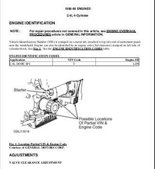
  • 1. 1998-99 ENGINES 2.4L 4-Cylinder ENGINE IDENTIFICATION Vehicle Identification Number (VIN) is stamped on a metal tab, attached to top left end of instrument panel, near the windshield. Engine can also be identified by an engine code (3rd character) stamped on left side of cylinder block. See Fig. 1 . See the ENGINE IDENTIFICATION CODES table. ENGINE IDENTIFICATION CODES Fig. 1: Locating Partial VIN & Engine Code Courtesy of GENERAL MOTORS CORP. ADJUSTMENTS VALVE CLEARANCE ADJUSTMENT NOTE: For repair procedures not covered in this article, see ENGINE OVERHAUL PROCEDURES article in GENERAL INFORMATION. Application VIN Code Engine ID 2.4L DOHC SFI T LD9 1999 Pontiac Grand Am GT 1998-99 ENGINES 2.4L 4-Cylinder 1999 Pontiac Grand Am GT 1998-99 ENGINES 2.4L 4-Cylinder me Wednesday, May 20, 2009 9:20:38 AM Page 1 © 2005 Mitchell Repair Information Company, LLC. me Wednesday, May 20, 2009 9:21:20 AM Page 1 © 2005 Mitchell Repair Information Company, LLC.
  • 2. Engine is equipped with non-adjustable hydraulic valve lifters. TROUBLE SHOOTING REMOVAL & INSTALLATION FUEL PRESSURE RELEASE Disconnect negative battery cable. Loosen fuel filler cap. Install Fuel Pressure Gauge (J-34730-1) on fuel pressure connector of fuel rail. Wrap shop towel around pressure connection when installing fuel pressure gauge to absorb fuel leakage. Install gauge bleed hose into container. Open bleed valve to bleed fuel pressure. COOLING SYSTEM BLEEDING 1. Fill radiator and surge tank to base of filler neck. Install pressure cap on surge tank. Block drive wheels and firmly apply parking brake. Shift automatic transaxle to Park or manual transaxle to Neutral. Start engine. Run until upper radiator hose is hot. Stop engine. 2. Observe coolant level in surge tank or radiator. If not above FULL mark, allow engine to cool and then remove surge tank cap. Add coolant. If low coolant light lights after servicing, remove surge tank cap and add coolant to bring level to COLD FULL mark when system is cold. ENGINE Removal (1998 Models) 1. Release fuel pressure. See FUEL PRESSURE RELEASE . Disconnect negative battery cable. Drain cooling system. Discharge air conditioning system (if equipped) using approved refrigerant NOTE: To trouble shoot mechanical engine components, see ENGINE MECHANICAL in GENERAL TROUBLE SHOOTING article in GENERAL INFORMATION. CAUTION: When battery is disconnected, vehicle computer and memory systems may lose memory data. Driveability problems may exist until computer systems have completed a relearn cycle. For 1998, see appropriate model under COMPUTER RELEARN PROCEDURES in COMPUTER RELEARN PROCEDURES article in GENERAL INFORMATION. For 1999, See appropriate model in COMPUTER RELEARN PROCEDURES article in GENERAL INFORMATION. NOTE: For reassembly reference, label all electrical connectors, vacuum hoses and fuel lines before removal. Also place mating marks on engine hood and other major assemblies before removal. NOTE: On 1998 models, remove engine and transaxle as an assembly through bottom of engine compartment. 1999 Pontiac Grand Am GT 1998-99 ENGINES 2.4L 4-Cylinder me Wednesday, May 20, 2009 9:20:38 AM Page 2 © 2005 Mitchell Repair Information Company, LLC.
  • 3. recovery/recycling equipment. 2. Remove left sound insulator and disconnect push rod from clutch pedal assembly (if equipped). Disconnect control cables, coolant hoses, electrical connectors, vacuum hoses, and fuel lines as necessary. Remove air cleaner assembly. Remove cooling fan. Disconnect air conditioning hose assembly from compressor (if equipped). Discard "O" rings. 3. Remove throttle cable and bracket. Remove power steering pump bolts and pump (leave hoses connected). Disconnect shift cables. Disconnect clutch actuator (slave cylinder) hydraulic line. Remove exhaust manifold and heat shield. See EXHAUST MANIFOLD . 4. Support engine from above with Engine Support Fixture (J-28467-A). Remove coolant recovery tank (leave hoses connected) and position aside. Remove engine mount from timing chain end of engine. Raise and support vehicle. Remove front wheels. Remove right splash shield. Remove engine mount strut and transaxle mount. Separate ball joints from steering knuckles. 5. Put a suitable supporting device under suspension support, crossmember and stabilizer shaft. Remove suspension support and stabilizer shaft. Remove heater outlet hose from radiator outlet pipe. Remove axle shaft from transaxle and intermediate shaft (manual transaxle only) and position aside. 6. Remove flywheel housing cover. Put a suitable supporting device under engine and transaxle assembly and lower vehicle onto support. Mark threads on engine upper support fixture hooks for installation reference. Remove engine upper support fixture hooks. Raise vehicle slowly from engine and transaxle assembly. Separate engine from transaxle (note bolt location for reassembly reference). Installation 1. Assemble engine to transaxle, ensuring bolts are in correct locations. On automatic transaxle models, clean torque converter bolts and bolt holes. Apply sealant to bolts. On all models, position engine and transaxle assembly under engine compartment. Lower vehicle until transaxle mount is aligned. Install transaxle mount bolt. 2. Install Engine Support Fixture (J-28467-A) above engine, adjusting it to previous setting. Install engine mount at timing chain end of engine. Install engine mount at transaxle. Raise vehicle. Remove supporting device from below engine and transaxle assembly. Install axle shafts. 3. Install suspension support, crossmember and stabilizer shaft assembly. Tighten suspension support rear bolts, center bolts and then front bolts to specification. See TORQUE SPECIFICATIONS table. Connect ball joints. Install engine mount strut. To complete installation, reverse removal procedure. Evacuate and charge air conditioning system. Fill cooling system and crankcase. Removal (1999 Models) 1. Release fuel pressure. See FUEL PRESSURE RELEASE . Disconnect negative battery cable. Drain cooling system and engine oil. Remove fuel rail assembly, air intake duct from air cleaner, ignition coil and module assembly. Disconnect control cables, coolant hoses, electrical connectors, vacuum hoses, and fuel lines as necessary. 2. Unbolt power steering pump and secure aside. Remove air intake duct bracket. Remove cruise control assembly and set aside. Install J 28467-360 engine support fixture. Remove fan belt and engine mount assembly. Raise engine using support fixture, then remove engine mount bracket. NOTE: On 1999 models, remove engine while leaving transmission in vehicle. 1999 Pontiac Grand Am GT 1998-99 ENGINES 2.4L 4-Cylinder me Wednesday, May 20, 2009 9:20:38 AM Page 3 © 2005 Mitchell Repair Information Company, LLC.
  • 4. 3. Raise and support vehicle. Remove front wheels and right splash shield. Remove crankshaft balancer. Remove torque converter bolts and oxygen sensor. Lower vehicle. Remove generator and starter. Remove exhaust brace bolt and exhaust manifold heat shield. Disconnect exhaust pipe from exhaust manifold. 4. Unbolt A/C compressor and secure aside. Remove oil pan-to-bellhousing bolts. Remove transmission mount. Remove transmission-to-engine bolts. Install engine hoist, then remove engine while supporting transaxle. Installation To install, reverse removal procedure. Tighten all fasteners to specifications. See TORQUE SPECIFICATIONS table. Fill engine fluids, and bleed cooling system. See COOLING SYSTEM BLEEDING . INTAKE MANIFOLD Removal 1. Disconnect negative battery cable. Disconnect electrical connectors and vacuum hoses from intake manifold components as necessary. Disconnect air intake tube. Remove throttle cable bracket. 2. Remove generator mount bolt. Remove EGR pipe from EGR adapter. Remove intake manifold nuts and bolts. Remove intake manifold and gasket. Installation Tighten all intake manifold nuts and bolts to specification in sequence. See Fig. 2 . See TORQUE SPECIFICATIONS table. To complete installation, reverse removal procedure. WARNING: Never remove intake manifold while engine is hot. Intake manifold is made of composite plastic and can be damaged if removed while engine is hot. NOTE: Intake manifold gasket is reusable unless damaged. Numbered side of intake manifold gasket must face intake manifold. 1999 Pontiac Grand Am GT 1998-99 ENGINES 2.4L 4-Cylinder me Wednesday, May 20, 2009 9:20:38 AM Page 4 © 2005 Mitchell Repair Information Company, LLC.
  • 5. Fig. 2: Intake Manifold Tightening Sequence Courtesy of GENERAL MOTORS CORP. EXHAUST MANIFOLD Removal 1. Disconnect negative battery cable. Disconnect oxygen sensor connector. Raise and support vehicle. Remove exhaust manifold brace bolt. Remove upper heat shield. Disconnect exhaust pipe flex decoupler from manifold. DO NOT allow flex decoupler to bend more than 3 degrees in any direction, as damage will result. 2. Pull down and back on exhaust pipe to disengage it from manifold. Lower vehicle. Remove exhaust manifold nuts. Remove exhaust manifold, seals and gaskets. Installation To install, reverse removal procedure using NEW gaskets. Tighten bolts to specification in sequence. See TORQUE SPECIFICATIONS table. See Fig. 3 . If oxygen sensor was removed, coat threads with Anti-Seize Compound (5612695) before installation. 1999 Pontiac Grand Am GT 1998-99 ENGINES 2.4L 4-Cylinder me Wednesday, May 20, 2009 9:20:39 AM Page 5 © 2005 Mitchell Repair Information Company, LLC.
  • 6. Fig. 3: Exhaust Manifold Tightening Sequence Courtesy of GENERAL MOTORS CORP. CYLINDER HEAD Removal 1. Disconnect negative battery cable. Drain cooling system. Remove throttle body-to-air cleaner duct. Disconnect heater hose and throttle body hose from water outlet. Remove power brake vacuum hose from throttle body. 2. Disconnect electrical connectors, vacuum hoses, and coolant hoses as necessary. Remove generator mount bolt. Remove intake manifold. See INTAKE MANIFOLD . Remove generator mount bolt. 3. Reinstall generator mount bolt. Install Engine Support Fixtures (J-28467-400 and J-28467-A). Remove exhaust manifold. See EXHAUST MANIFOLD . Remove ignition coil and module assembly connectors. Remove attaching bolts and remove coil assembly from camshaft housing by pulling it straight up. See Fig. 12 . 4. Disconnect camshaft position sensor connector. Remove power steering pump. Remove fuel line retaining clamp from bracket on top of intake camshaft housing. Remove fuel rail from cylinder head, and leaving fuel lines attached, position on top of master cylinder. Cover injector openings in head and injector nozzles. 5. Remove timing chain and sprocket. See TIMING CHAIN, SPROCKETS & TENSIONER . CAUTION: Turn camshaft housing upside down immediately after removing from vehicle, or valve lifters will fall out and may be damaged. 1999 Pontiac Grand Am GT 1998-99 ENGINES 2.4L 4-Cylinder me Wednesday, May 20, 2009 9:20:39 AM Page 6 © 2005 Mitchell Repair Information Company, LLC.
  • 7. Disconnect timing chain housing at intake camshaft housing but DO NOT remove from vehicle. Remove bolts attaching intake camshaft housing to cylinder head bolts in reverse of tightening sequence. See Fig. 13 . Remove camshaft housing. Repeat procedure with exhaust camshaft housing. 6. Disconnect radiator inlet hose from coolant outlet and disconnect coolant temperature sensor connectors. Remove cylinder head bolts in reverse order of tightening sequence. See Fig. 4 . Remove cylinder head and gasket. See CYLINDER HEAD under OVERHAUL. Installation Clean threads of cylinder head bolts and bolt holes. Lightly coat bolt threads with engine oil. Install NEW gasket, ensuring all holes are aligned with cylinder block. Install cylinder head and tighten cylinder head bolts to specification in sequence. See TORQUE SPECIFICATIONS table. To complete installation, reverse removal procedure. See Fig. 4 . Fig. 4: Cylinder Head Bolt Tightening Sequence Courtesy of GENERAL MOTORS CORP. FRONT COVER CAUTION: DO NOT use a thread tap to clean cylinder head bolt holes. Remove all fluids from bolt holes. 1999 Pontiac Grand Am GT 1998-99 ENGINES 2.4L 4-Cylinder me Wednesday, May 20, 2009 9:20:39 AM Page 7 © 2005 Mitchell Repair Information Company, LLC.
  • 8. Removal 1. Disconnect negative battery cable. Drain cooling system. Remove coolant recovery tank. Remove serpentine drive belt. Remove generator (leave wiring attached). Attach Engine Support Fixture (J-28467- 400 and J-28467-A) to engine and generator stud. Remove bolts from upper half of front cover. 2. Remove engine mount assembly from timing chain end of engine. Remove engine mounting bracket adapter. Raise and support vehicle. Remove right front wheel and splash shield. Remove crankshaft balancer bolt. Remove crankshaft balancer with a puller. Remove lower bolts from front cover. Lower vehicle. Remove front cover and gaskets. Installation To install, reverse removal procedure. Cover gasket is reusable if not damaged. Lubricate front seal with grease before installing crankshaft balancer. To complete installation, reverse removal procedure. Tighten nuts and bolts to specification. See TORQUE SPECIFICATIONS table. Fill cooling system. CRANKSHAFT FRONT SEAL Removal & Installation Disconnect negative battery cable. Remove front cover. See FRONT COVER . Support cover, and drive seal through rear of cover. Take care not to damage cover. Note direction of seal installation. To install seal, use Seal Installer (J-36010). TIMING CHAIN, SPROCKETS & TENSIONER Removal 1. Disconnect negative battery cable. Remove front cover. See FRONT COVER . See Fig. 5 . Rotate crankshaft in normal direction of rotation (clockwise, as viewed from front of engine) until cylinder No. 1 is at TDC of compression stroke. 2. The camshaft sprocket dowel pin hole should line up with holes on timing chain housing. The crankshaft sprocket keyway should point upwards. See Fig. 5 . Remove timing chain guides. Raise and support vehicle. Ensure slack in chain is above tensioner assembly, then remove chain tensioner. 3. Note that timing chain must be disengaged from any wear grooves in tensioner shoe before removing shoe. Slide a screwdriver blade between chain and tensioner shoe, while pulling shoe outward (this should disengage chain from wear grooves in shoe). If timing chain is not difficult to remove, go to step 5 . If it is difficult to remove timing chain shoe, go to next step. NOTE: This procedure has been revised due to GM service manual update (SMU) # 00- 06-01-002 dated Feb, 2000 CAUTION: To prevent severe engine damage, carefully follow procedure. 1999 Pontiac Grand Am GT 1998-99 ENGINES 2.4L 4-Cylinder me Wednesday, May 20, 2009 9:20:39 AM Page 8 © 2005 Mitchell Repair Information Company, LLC.
  • 9. 4. Lower vehicle. Hold intake camshaft sprocket with Sprocket Wrench (J-39579) and remove sprocket bolt. Remove washer from bolt and rethread bolt into camshaft by hand. Remove camshaft sprocket using a 3- jaw puller. DO NOT attempt to pry sprocket off or damage will result. 5. Remove tensioner assembly bolts and tensioner. Mark outer surface of timing chain and crankshaft sprocket for reassembly reference. Remove timing chain. Fig. 5: Assembled View Of Timing Chain, Sprockets & Tensioner Courtesy of GENERAL MOTORS CORP. Installation CAUTION: To prevent damage to sprocket or timing chain housing, use a puller to remove sprocket from camshaft. DO NOT pry sprocket from camshaft. 1999 Pontiac Grand Am GT 1998-99 ENGINES 2.4L 4-Cylinder me Wednesday, May 20, 2009 9:20:39 AM Page 9 © 2005 Mitchell Repair Information Company, LLC.
  • 10. 1. Install the camshaft sprockets. The sprockets are identical and interchangeable. Clean the old sealer off of the bolts with a wire brush. Clean the threaded hole in the camshaft with a nylon bristle brush. Coat the camshaft bolts with Adhesive/Sealant Compound (GM 1234593) or equivalent. See Fig. 6 . 2. Install the camshaft sprocket bolts and washers while holding the sprockets with Tool (J- 39579). Tighten the bolts to 52 ft. lbs. (70 N.m). 3. Install Tool (J-36008-A) through the holes in the camshaft sprockets and into the holes in the timing chain housing. This will position the camshaft for correct timing. Use the following steps if the camshafts are out of position and must be rotated more than 1/8 turn in order to install the alignment dowel pins: A. The crankshaft must be rotated 90 degrees clockwise from TDC to give the valves adequate clearance to open. B. Once the camshafts are in position and the dowels are installed, rotate the crankshaft counter clockwise back to TDC. 4. Install the timing chain over the exhaust camshaft sprocket around the coolant pump sprocket and around the crankshaft sprocket. Remove the alignment dowel pin from the intake camshaft. Use Tool (J-39579) in order to rotate the intake camshaft sprocket counter clockwise enough to allow the timing chain to slide over the intake camshaft sprocket. Release Tool (J-39579). The length of the chain between the two camshaft sprockets will tighten. 5. If properly timed, the intake camshaft alignment dowel pin will slide in easily. If the dowel pin does not fully index, the camshafts are not timed correctly and the procedure must be repeated. Leave the alignment dowel pins installed. The keyway on the crankshaft and the mark on the cylinder block should be aligned when the slack is removed from the chain between the intake camshaft sprocket and the crankshaft sprocket. If the mark and the keyway are not aligned, move the chain one tooth forward or rearward. Remove the slack and recheck the marks. NOTE: Ensure camshaft sprocket alignment pins are in the cylinder block and the timing chain housing, prior to installing the timing chain housing. The camshaft sprocket alignment pins ensure proper chain housing and front cover location for correct front oil seal to crankshaft alignment. CAUTION: DO NOT rotate the crankshaft clockwise to TDC. Valve or piston damage could occur. The timing chain and crankshaft sprocket must be put in a specific direction for chain noise and wear considerations. The surfaces that were marked during removal should be showing when the chain and crankshaft sprocket are installed. NOTE: Use the following steps in order to reset the timing chain tensioner assembly to the zero position: A. Reset the timing chain tensioner assembly. B. Insert the tensioner plunger assembly into the tensioner housing. C. With the tensioner plunger fully extended, turn the complete 1999 Pontiac Grand Am GT 1998-99 ENGINES 2.4L 4-Cylinder me Wednesday, May 20, 2009 9:20:39 AM Page 10 © 2005 Mitchell Repair Information Company, LLC.
  • 11. 6. Check the plunger to ensure the plunger is out of the cylinder at the correct dimension. The correct dimension for the plunger to extend out of the cylinder is .070" (1.7 mm) maximum. See Fig. 8 . Loosely install the tensioner assembly and bolts to the timing chain housing. See Fig. 9 . Install the timing chain tensioner shoe on the stud. Apply hand pressure to the timing chain tensioner shoe until the locking tab seats in the groove in the stud. Tighten the timing chain tensioner bolts. DO NOT over tighten. Tighten the bolts to 89 INCH lbs. (10 N.m). 7. Release the timing chain tensioner plunger using the following procedure: A. Using a flat blade screwdriver, cotter pin remover, or a similar tool, press firmly against the face of the timing chain tensioner plunger. See Fig. 10 . B. Depress the timing chain tensioner plunger until the plunger is bottomed out in the bore of the timing chain tensioner. See Fig. 8 . C. Release the tensioner plunger. See Fig. 10 . The plunger should press firmly against the back of the timing chain tensioner shoe. Remove Tool (J- 36008-A) from the camshaft sprockets. 8. Rotate the crankshaft clockwise two full rotations. Align the crankshaft keyway with the mark on the cylinder block and reinstall the alignment dowel pins. The alignment dowel pins will slide in easily if the engine is timed correctly. Install the timing chain guides. assembly upside down on a bench or other flat surface. See Fig. 7 . D. With the plunger face against the workbench, press firmly on the bottom of the tensioner housing. E. Compress the plunger until the plunger is seated flush in the tensioner. See Fig. 8 . CAUTION: If the timing chain tensioner plunger is not released from the installation position, engine damage will occur when the engine is started. NOTE: If the timing chain tensioner plunger cannot be depressed, the plunger is not properly reset and the procedure for resetting the timing chain tensioner should be repeated. CAUTION: Beginning with the 1998 model year, the timing chain on the LD9 (VIN T) Twin Cam Engine is different from the chain found on earlier versions of this engine, and is not to be replaced with a timing chain from earlier model year engines. The timing sprockets were also changed beginning in 1998, and the shape of the chain links matches the sprockets. Engine damage may result if the wrong timing chain is used. The timing chain and the crankshaft sprocket must be marked so that they are reinstalled in the same side facing out at the time of assembly. 1999 Pontiac Grand Am GT 1998-99 ENGINES 2.4L 4-Cylinder me Wednesday, May 20, 2009 9:20:39 AM Page 11 © 2005 Mitchell Repair Information Company, LLC.
  • 12. Fig. 6: Installing Timing Chain Sprockets Courtesy of GENERAL MOTORS CORP. 1999 Pontiac Grand Am GT 1998-99 ENGINES 2.4L 4-Cylinder me Wednesday, May 20, 2009 9:20:39 AM Page 12 © 2005 Mitchell Repair Information Company, LLC.
  • 13. Fig. 7: Released View Of Timing Chain Tensioner Assembly Courtesy of GENERAL MOTORS CORP. 1999 Pontiac Grand Am GT 1998-99 ENGINES 2.4L 4-Cylinder me Wednesday, May 20, 2009 9:20:39 AM Page 13 © 2005 Mitchell Repair Information Company, LLC.
  • 14. Fig. 8: Compressed View Of Timing Chain Tensioner Assembly Courtesy of GENERAL MOTORS CORP. 1999 Pontiac Grand Am GT 1998-99 ENGINES 2.4L 4-Cylinder me Wednesday, May 20, 2009 9:20:39 AM Page 14 © 2005 Mitchell Repair Information Company, LLC.
  • 15. Fig. 9: Installing Shoe & Timing Chain Tensioner Assembly Courtesy of GENERAL MOTORS CORP. 1999 Pontiac Grand Am GT 1998-99 ENGINES 2.4L 4-Cylinder me Wednesday, May 20, 2009 9:20:39 AM Page 15 © 2005 Mitchell Repair Information Company, LLC.
  • 16. Fig. 10: Releasing Timing Chain Tensioner Assembly Courtesy of GENERAL MOTORS CORP. TIMING CHAIN HOUSING 1999 Pontiac Grand Am GT 1998-99 ENGINES 2.4L 4-Cylinder me Wednesday, May 20, 2009 9:20:39 AM Page 16 © 2005 Mitchell Repair Information Company, LLC.
  • 17. Removal 1. Disconnect negative battery cable. Remove front cover. See FRONT COVER . Raise and support vehicle. Drain cooling system by disconnecting heater hose from thermostat housing. Remove nuts securing water pump to timing chain housing. Remove timing chain and tensioner, making sure to mark chain and sprocket outside surfaces. See TIMING CHAIN, SPROCKETS & TENSIONER . 2. Remove fasteners attaching timing chain housing to block. Remove 4 bolts securing oil pan to front cover. Remove stud from lowest point on timing chain housing (if left installed, stud prevents removal of housing). 3. Lower vehicle. Hold camshaft sprockets with Sprocket Wrench (J-39579) and remove sprocket bolts. Remove bolts securing timing chain housing to camshaft housings. Remove timing chain housing and gaskets (if necessary, raise engine slightly from above). 4. If necessary, remove timing chain idler sprocket and bearing. See TIMING CHAIN IDLER SPROCKET & BEARING . Installation 1. Replace oil pan gasket if damaged. If silicone bead at corner joints is damaged, repair it by applying just enough Silicone Sealant (12345739) to restore it to its original dimension (too much sealant may cause part misalignment, resulting in oil leaks). 2. Ensure dowel pins are installed in cylinder block. Install timing chain housing with NEW gaskets (without sealer). Install and hand-tighten all timing chain housing bolts, then tighten to specification. See TORQUE SPECIFICATIONS table. To install remaining components, reverse removal procedure. Fill cooling system. TIMING CHAIN IDLER SPROCKET & BEARING Removal 1. Remove timing chain housing. See TIMING CHAIN HOUSING . Remove snap ring securing bearing in housing. See Fig. 11 . Install Remover/Installer Plate (J-36998-4) on front side of housing, engaging alignment pins into bolt holes in housing. 2. Using Handle (J-36998-2), press sprocket out of bearing. Reposition remover/installer plate onto rear side of housing, engaging water pump studs into holes in plate. Using Remover/Installer (J-36998-1) and Handle (J-36998-2), press bearing out of housing. Installation Clean snap ring groove in housing. Coat surfaces of housing and NEW bearing with Sealant (12345493). Install remover/installer plate on front side of housing. Using remover/installer and handle, press bearing into housing. NOTE: Timing chain housing does not need to be completely removed if replacing gasket between cylinder head or cylinder block and timing chain housing. NOTE: Replace bearing whenever idler sprocket is removed. 1999 Pontiac Grand Am GT 1998-99 ENGINES 2.4L 4-Cylinder me Wednesday, May 20, 2009 9:20:39 AM Page 17 © 2005 Mitchell Repair Information Company, LLC.
  • 18. Reposition remover/installer plate to rear side of housing. Using remover/installer and handle, press idler sprocket through bearing. Install bearing snap ring. Install timing chain housing. See TIMING CHAIN HOUSING . Fig. 11: Exploded View Of Timing Chain Idler Sprocket Assembly Courtesy of GENERAL MOTORS CORP. INTAKE CAMSHAFT & HOUSING Removal 1. Disconnect negative battery cable. Disconnect ignition coil electrical connector. Remove bolts, and remove ignition coil and module assembly by pulling it straight up. See Fig. 12 . It may be necessary to use Spark Plug Wire Remover (J-36011) to break plug wire connectors loose by twisting and then pulling. 2. Disconnect camshaft position sensor connector. Remove power steering pump and set aside (leave hoses connected). Disconnect vacuum line from fuel pressure regulator. Disconnect fuel injector harness connector. Remove fuel line clamp from top of intake camshaft housing. Remove fuel rail bolts. 3. Remove fuel rail (leave fuel lines attached). Cover injector openings in cylinder head. Cover injector nozzles. Remove timing chain and camshaft sprockets. See TIMING CHAIN, SPROCKETS & TENSIONER . Remove bolts securing timing chain housing to camshaft housing. CAUTION: Any time camshaft housing bolts are loosened or removed, gasket between camshaft housing and cylinder head must be replaced. 1999 Pontiac Grand Am GT 1998-99 ENGINES 2.4L 4-Cylinder me Wednesday, May 20, 2009 9:20:39 AM Page 18 © 2005 Mitchell Repair Information Company, LLC.
  • 19. 4. Remove bolts that secure camshaft housing cover to camshaft housing. Working in reverse order of tightening sequence, evenly loosen and remove bolts securing camshaft housing to cylinder head (leave 2 bolts loosely in place to keep camshaft housing in place while separating cover from housing). See Fig. 13 . 5. Install 4 camshaft housing-to-cylinder head bolts into tapped holes in camshaft housing cover. Evenly tighten bolts to separate cover from housing. Remove 2 loosely installed camshaft housing bolts. Remove camshaft housing cover and seals. 6. Install and hand-tighten one camshaft housing bolt to keep camshaft housing in place while removing camshaft and lifters. For installation reference, note position of dowel pin (on timing chain sprocket) in relation to camshaft housing. Remove camshaft. Remove camshaft housing and lifters as an assembly. If necessary, remove lifters from camshaft housing. Inspection If camshaft journal diameter, lobe lift, end play or oil clearance is not within specification, replace components as necessary. See CAMSHAFT SPECIFICATIONS table under ENGINE SPECIFICATIONS. Check camshaft housing. See CAMSHAFT HOUSING under OVERHAUL. Installation 1. Ensure dowel pins aligning camshaft housing with cylinder head are installed. Install camshaft housing with a NEW gasket (no sealant required). Loosely install one camshaft housing bolt to keep camshaft housing in place while installing lifters and camshaft. 2. Coat lifters and camshaft with Prelube (12345501). Install lifters in their original locations. Install camshaft, ensuring dowel pin on timing chain sprocket is in same position as when removed. Dowel pin should point straight up and lined up with centerline of lifter bore. Install NEW Green camshaft housing cover seals into cover (no sealant is required). 3. Remove bolt installed to keep camshaft housing in place. Apply GM Pipe Sealant (1052080) to threads of bolts securing housing to cylinder head and cover to housing. Tighten camshaft housing bolts to specification in sequence. See Fig. 13 . Note that bolts 11 and 12 have a different final torque than bolts 1-10. See TORQUE SPECIFICATIONS table. 4. Install timing chain housing and timing chain in reverse order of removal. Lubricate NEW "O" ring seals with engine oil, and install them onto injectors. Install fuel rail. To install remaining components, reverse removal procedure. 5. If a spark plug boot connector remained on a spark plug when ignition coil and module assembly was removed, remove it from spark plug and install it onto ignition coil and module assembly. Set ignition coil and module assembly in place and press straight down to install assembly onto spark plugs. NOTE: If removing lifters, keep them in order; they must be installed in their original locations. To prevent bleed-down, store lifters upside down in clean engine oil. NOTE: If replacing camshaft or lifters, add Engine Oil Supplement (1052367) to crankcase. If camshaft is replaced, lifters must also be replaced. 1999 Pontiac Grand Am GT 1998-99 ENGINES 2.4L 4-Cylinder me Wednesday, May 20, 2009 9:20:39 AM Page 19 © 2005 Mitchell Repair Information Company, LLC.
  • 20. 6. Clean oil from threads of bolts securing assembly to camshaft housing. Apply GM Pipe Sealant (1052080) to ignition coil-to-camshaft housing bolt threads. To complete installation, reverse removal procedure. Fig. 12: Camshaft Housing & Ignition Coil/Module Assembly Courtesy of GENERAL MOTORS CORP. 1999 Pontiac Grand Am GT 1998-99 ENGINES 2.4L 4-Cylinder me Wednesday, May 20, 2009 9:20:39 AM Page 20 © 2005 Mitchell Repair Information Company, LLC.
  • 21. Fig. 13: Camshaft Housing Bolt Tightening Sequence Courtesy of GENERAL MOTORS CORP. EXHAUST CAMSHAFT & HOUSING Removal 1. Disconnect negative battery cable. Disconnect ignition coil electrical connector. Remove bolts, and remove ignition coil and module assembly by pulling it straight up. See Fig. 12 . It may be necessary to use Spark Plug Wire Remover (J-36011) to break plug wire connectors loose by twisting and then pulling. 2. Disconnect oil pressure switch connector. Disconnect timing chain housing at exhaust camshaft housing but DO NOT remove from vehicle. See TIMING CHAIN HOUSING . Remove exhaust camshaft cover CAUTION: Any time camshaft housing bolts are loosened or removed, gasket between camshaft housing and cylinder head must be replaced. 1999 Pontiac Grand Am GT 1998-99 ENGINES 2.4L 4-Cylinder me Wednesday, May 20, 2009 9:20:39 AM Page 21 © 2005 Mitchell Repair Information Company, LLC.
  • 22. and gasket. 3. Working in reverse order of tightening sequence, evenly loosen and remove bolts securing camshaft housing to cylinder head (leave 2 bolts loosely in place to keep camshaft housing in place while separating cover from housing). See Fig. 13 . Install 4 camshaft housing-to-cylinder head bolts into tapped holes in camshaft housing cover. 4. Evenly tighten bolts to separate cover from housing. Remove 2 loosely installed camshaft housing bolts. Remove camshaft housing cover and seals. 5. Install and hand-tighten one camshaft housing bolt to keep camshaft housing in place while removing camshaft and lifters. For installation reference, note position of dowel pin (on timing chain sprocket) in relation to camshaft housing. Remove camshaft. Remove camshaft housing and lifters as an assembly. If necessary, remove lifters from camshaft housing. Inspection If camshaft journal diameter, lobe lift, end play or oil clearance is not within specification, replace components as necessary. See CAMSHAFT SPECIFICATIONS table under ENGINE SPECIFICATIONS. Check camshaft housing. See CAMSHAFT HOUSING under OVERHAUL. Installation 1. Ensure dowel pins aligning camshaft housing with cylinder head are installed. Install camshaft housing with NEW gasket (no sealant required). Loosely install one camshaft housing bolt to keep camshaft housing in place while installing lifters and camshaft. 2. Coat lifters and camshaft with Prelube (12345501). Install lifters in their original locations. Install camshaft, ensuring dowel pin on timing chain sprocket is in same position as when removed. Dowel pin should point straight up and lined up with centerline of lifter bore. Install NEW Orange seals into cover (no sealant is required). 3. Remove bolt installed to keep camshaft housing in place. Apply GM Pipe Sealant (1052080) to threads of bolts securing housing to cylinder head and cover to housing. Tighten camshaft housing bolts to specification in sequence. See Fig. 13 . Note that bolts 11 and 12 have a different final torque than bolts 1-10. See TORQUE SPECIFICATIONS table. 4. Install timing chain housing and timing chain in reverse order of removal. To install remaining components, reverse removal procedure. If a spark plug boot connector remained on a spark plug when ignition coil and module assembly was removed, remove connector from spark plug and install it onto ignition coil and module assembly. 5. Set ignition coil and module assembly in place and press straight down to install assembly onto spark plugs. Clean oil from threads of bolts securing assembly to camshaft housing. Apply GM Pipe Sealant NOTE: If removing lifters, keep them in order; they must be installed in their original locations. To prevent bleed-down, store lifters upside down in clean engine oil. NOTE: If replacing camshaft or lifters, add Engine Oil Supplement (1052367) to crankcase. If camshaft is replaced, lifters must also be replaced. 1999 Pontiac Grand Am GT 1998-99 ENGINES 2.4L 4-Cylinder me Wednesday, May 20, 2009 9:20:39 AM Page 22 © 2005 Mitchell Repair Information Company, LLC.
  • 23. (1052080) to ignition coil-to-camshaft housing bolt threads. To complete installation, reverse removal procedure. CRANKSHAFT REAR OIL SEAL Removal 1. Disconnect negative battery cable. Remove transaxle. For M/T, see appropriate article in CLUTCHES. For A/T, see appropriate REMOVAL & INSTALLATION - A/T article in TRANSAXLE/TRANSMISSIONS. 2. On manual transaxle models, mark pressure plate in relation to flywheel for installation reference. Remove flexplate/flywheel assembly. Remove oil pan-to-seal housing bolts. Remove seal housing-to- block bolts and gasket. See Fig. 25 . 3. Note direction of seal installation. Lay seal housing onto 2 wood blocks, with transaxle side of seal housing facing down. To prevent seal housing damage, ensure wood blocks that seal housing are supported across dowel pin and center bolt holes on both sides of seal opening. Using a small chisel in seal relief grooves, evenly drive seal out of seal housing without scraping sealing surface. Installation 1. Using Crankshaft Rear Seal Installer (J-36005), press NEW seal into housing. Replace oil pan gasket if damaged. If silicone bead at corner joints is damaged, repair it by applying just enough Silicone Sealant (12345739) to restore it to its original dimension (too much sealant may cause part misalignment, resulting in oil leaks). 2. Set NEW seal housing-to-block gasket in place on dowel pins. Lubricate NEW seal lip with engine oil. Install seal housing, but DO NOT install oil pan bolts. Tighten bolts securing seal housing to cylinder block to specification. See TORQUE SPECIFICATIONS table. Install and tighten oil pan-to-seal housing bolts to specification. 3. To install remaining components, reverse removal procedure. Apply Sealant (12345493) to flexplate/flywheel bolts before installing them. Align reference marks on pressure plate and flywheel (manual transmission). OIL FLOW CHECK VALVE Removal 1. Oil flow check valve is located below surface of cylinder block deck, near front of engine, and is accessible with cylinder head removed. See Fig. 28 . Attach a slide hammer to check valve using Check Valve Remover (J-38123) or a modified common 3/16 x 4" round-head machine screw. To modify screw, grind 2 flat spots on outside diameter of screw head, parallel with screwdriver slot and 180 degrees across from each other. CAUTION: During check valve removal, DO NOT allow tool to impact ball at bottom of check valve, as this may cause ball to dislodge. If check ball is dislodged, it may fall into oil galley. Locate check ball if it is missing. 1999 Pontiac Grand Am GT 1998-99 ENGINES 2.4L 4-Cylinder me Wednesday, May 20, 2009 9:20:39 AM Page 23 © 2005 Mitchell Repair Information Company, LLC.
  • 24. 2. Insert check valve remover (or modified machine screw) into check valve, then rotate tool 90 degrees so it will lock into indentations in check valve. DO NOT allow tools to contact check ball as it can drop into engine oil galleries. Pull check valve out of its bore. Installation If check ball is missing, it has dropped into oil galleries and must be retrieved before installation. Using slide hammer and check valve remover (opposite end), or a hammer and drift punch, drive NEW check valve into its bore until it is seated (normally, check valve will seat slightly below surface). A distinct change of sound will result when check valve seats. VALVE LIFTERS Removal & Installation To remove and install valve lifters, remove camshafts and camshaft housings. See INTAKE CAMSHAFT & HOUSING . Also See EXHAUST CAMSHAFT & HOUSING . RADIATOR (ACHIEVA, GRAND AM & SKYLARK) Removal 1. Disconnect the negative battery cable 2. Drain the cooling system. Recover the coolant. 3. Remove the air intake duct assembly by removing the air cleaner outlet resonator mounting screws. Disconnect the air cleaner outlet resonator clamp at throttle body. Remove the air cleaner outlet duct from air cleaner outlet resonator and air cleaner assembly. Disconnect the crankcase vent hose from the air cleaner outlet resonator. Remove the air cleaner outlet resonator. 4. Disconnect the upper transaxle oil cooler line from the radiator (Automatic Transmission). 5. Disconnect the radiator inlet hose and the clamp from the radiator 6. Raise the vehicle. See JACKING & HOISTING in SPECIFICATIONS & PROCEDURES article in WHEEL ALIGNMENT. CAUTION: Before servicing any electrical component, the ignition key must be in the OFF or LOCK position and all electrical loads must be OFF, unless instructed otherwise in these procedures. If a tool or equipment could easily come in contact with a live exposed electrical terminal, also disconnect the negative battery cable. Failure to follow these precautions may cause personal injury and/or damage to the vehicle or its components. NOTE: When adding coolant, it is important that you use GM Goodwrench DEX-COOL (tm) coolant. If coolant other than DEX-COOL(tm) is added to the system, the engine coolant will require change sooner: at 30,000 miles (50 000 km) or 24 months. 1999 Pontiac Grand Am GT 1998-99 ENGINES 2.4L 4-Cylinder me Wednesday, May 20, 2009 9:20:39 AM Page 24 © 2005 Mitchell Repair Information Company, LLC.
  • 25. 7. Disconnect the lower transaxle oil cooler line from the radiator. 8. Remove the cooling fan by removing the cooling fan bracket bolt. Disconnect the wiring harness connector from the fan motor. Remove the cooling fan assembly. 9. Remove the splash shield that is below the radiator outlet hose. 10. Disconnect the radiator outlet hose from the radiator. 11. Lower the vehicle. 12. Remove the retaining clip from the condenser line 13. Remove the condenser to radiator bolts. 14. Disconnect the surge tank inlet hose and the clamp from the radiator. 15. Remove the radiator retaining bolts and the mounts. 16. Remove the radiator. Installation 1. Install the radiator 2. Install the radiator mounts and the bolts Tighten the bolts to 89 INCH lbs. (10 N.m). 3. Connect the surge tank inlet hose and the clamp to the radiator 4. Install the radiator to condenser bolts. Install the retaining clip to the condenser line. 5. Raise the vehicle. 6. Connect the radiator outlet hose and the clamp to the radiator. 7. Install the splash shield that is below the radiator outlet hose. 8. Install the cooling fan. 9. Connect the lower transaxle oil cooler line to the radiator (Automatic Transmission). Tighten the transaxle oil cooler line fitting to 22 ft. lbs. (30 N.m). 10. Lower the vehicle. 11. Connect the radiator inlet hose and the clamp to the radiator. 12. Connect the upper transaxle oil cooler line to the radiator (Automatic Transmission). Tighten the transaxle oil cooler line fitting to 22 ft. lbs. (30 N.m). 13. Connect the air intake duct assembly. 14. Fill the cooling system. Bleed cooling system and check for leaks. See COOLING SYSTEM BLEEDING . RADIATOR (ALERO) NOTE: After servicing the cooling system, an intermittent low coolant lamp may illuminate during extreme driving maneuvers. In order to eliminate this condition, remove the surge tank cap and add coolant to a level at or above the split line of the tank when the system is cold. CAUTION: Before servicing any electrical component, the ignition key must be in the 1999 Pontiac Grand Am GT 1998-99 ENGINES 2.4L 4-Cylinder me Wednesday, May 20, 2009 9:20:39 AM Page 25 © 2005 Mitchell Repair Information Company, LLC.
  • 26. Removal 1. Disconnect negative battery cable. Disconnect positive battery cable. Remove the retainer bolt and retainer. Remove the battery and battery insulator from vehicle. 2. Remove the battery tray screws and the battery tray. 3. Evacuate the A/C system using approved recover and recycling procedures. See EVACUATING A/C SYSTEM . 4. Drain the cooling system. Recover the coolant. 5. Remove the upper radiator hose. 6. Remove the upper transaxle cooler line. 7. Remove the coolant surge tank hose. 8. Remove the condenser inlet fitting from the discharge hose. 9. Disconnect the cooling fan electrical connection. 10. Raise the vehicle. See JACKING & HOISTING in SPECIFICATIONS & PROCEDURES article in WHEEL ALIGNMENT. 11. Remove the lower closeout panel. 12. Remove the lower radiator hose from the radiator. 13. Remove the lower transaxle cooler line. 14. Remove the evaporator line from the condenser outlet. 15. Remove the lower radiator mounting panel. 16. Remove the radiator, fan and condenser as an assembly from the vehicle. 17. Remove the condenser from the radiator. 18. Remove the fan shroud from the radiator. Installation 1. Install the fan shroud to the radiator. 2. Install the condenser to the radiator. Tighten the bolt to 44 INCH lbs. (5 N.m). 3. Install the radiator, fan, and condenser as an assembly to the vehicle. OFF or LOCK position and all electrical loads must be OFF, unless instructed otherwise in these procedures. If a tool or equipment could easily come in contact with a live exposed electrical terminal, also disconnect the negative battery cable. Failure to follow these precautions may cause personal injury and/or damage to the vehicle or its components. NOTE: When adding coolant, it is important that you use GM Goodwrench DEX-COOL (tm) coolant. If coolant other than DEX-COOL(tm) is added to the system, the engine coolant will require change sooner: at 30,000 miles (50 000 km) or 24 months. 1999 Pontiac Grand Am GT 1998-99 ENGINES 2.4L 4-Cylinder me Wednesday, May 20, 2009 9:20:39 AM Page 26 © 2005 Mitchell Repair Information Company, LLC.
  • 27. 4. Install the lower radiator mounting panel. Tighten the bolts to 89 INCH lbs. (10 N.m) 5. Install the condenser outlet to the evaporator line. Tighten the bolt to 18 ft. lbs. (25 N.m). 6. Install the lower radiator hose to the radiator. 7. Install the lower closeout panel. 8. Lower the vehicle. Install the cooling fan electrical connection. 9. Install the lower transaxle cooler line. Tighten the bolt to 22 ft. lbs. (30 N.m). 10. Install the condenser inlet fitting to the discharge hose. Tighten the bolt to 18 ft. lbs. (25 N.m). 11. Install the coolant surge tank hose. 12. Install the upper transaxle cooler line. Tighten the bolt to 22 ft. lbs. (30 N.m). 13. Install the upper radiator hose. 14. Refill the cooling system. 15. Recharge the A/C system. See CHARGING A/C SYSTEM in GENERAL SERVICING article in HEATING & AIR CONDITIONING. 16. Install the battery tray. 17. Install the battery. 18. Start engine. Bleed cooling system. See COOLING SYSTEM BLEEDING . Inspect the cooling system for leaks. RADIATOR (CAVALIER & SUNFIRE) Removal 1. Disconnect the negative battery cable. NOTE: After servicing the cooling system, and if the vehicle is equipped with an intermittent low coolant light, an occasional low coolant light may be encountered during some extreme driving maneuvers. This complaint should be eliminated by removing the surge tank cap and adding coolant to a level just at or above the full cold line when the system is cold. CAUTION: Before servicing any electrical component, the ignition key must be in the OFF or LOCK position and all electrical loads must be OFF, unless instructed otherwise in these procedures. If a tool or equipment could easily come in contact with a live exposed electrical terminal, also disconnect the negative battery cable. Failure to follow these precautions may cause personal injury and/or damage to the vehicle or its components. NOTE: When adding coolant, it is important that you use GM Goodwrench DEX-COOL (tm) coolant. If coolant other than DEX-COOL(tm) is added to the system, the engine coolant will require change sooner: at 30,000 miles (50 000 km) or 24 months. 1999 Pontiac Grand Am GT 1998-99 ENGINES 2.4L 4-Cylinder me Wednesday, May 20, 2009 9:20:39 AM Page 27 © 2005 Mitchell Repair Information Company, LLC.
  • 28. 2. Disable the SIR system. See DISABLING & ACTIVATING AIR BAG SYSTEM in AIR BAG RESTRAINT SYSTEMS article in RESTRAINTS. 3. Drain the engine coolant. Recover the coolant. 4. Remove the hood latch support from the radiator upper tie bar. 5. Remove the right and left headlamp assemblies by removing the upper air intake splash shield. Remove the headlamp assembly bolts. Remove the socket/bulb. Remove the housing/lens assembly from the bracket. Remove the screws and the adjusters if necessary. 6. Remove the radiator upper mounting bolts and the upper radiator mounts 7. Raise and suitably support the vehicle. See JACKING & HOISTING in SPECIFICATIONS & PROCEDURES article in WHEEL ALIGNMENT. 8. Remove the SIR Connector Position Assurance (CPA) from the inflatable restraint front end forward discriminating sensor harness connector. Disconnect the inflatable restraint front end discriminating sensor harness connector from the sensor. Note routing of harness for installation reference. 9. Remove the cooling fan assembly. Raise the vehicle. Remove the cooling fan mounting bolt. Disconnect the electrical connector from the cooling fan. Remove the cooling fan assembly by pulling the fan assembly out through the bottom of the vehicle. 10. Disconnect the radiator outlet hose from the radiator. 11. Disconnect the lower transmission oil cooler line from the radiator. 12. Lower the vehicle. 13. Remove the hood latch support bracket and the forward discriminating sensor with the harness. 14. Disconnect the upper transmission oil cooler line from the radiator. 15. Disconnect the radiator inlet hose from the radiator. 16. Disconnect the surge tank inlet hose and the clamp from the radiator. 17. Remove the condenser from the radiator, if equipped. It is not necessary to discharge the A/C System. 18. Remove the radiator assembly from the vehicle. Installation 1. Install the radiator assembly to the vehicle. 2. Install the condenser to the radiator. 3. Connect the surge tank overflow hose to the radiator. 4. Install the hood latch bracket. Route the forward discriminating sensor harness. 5. Raise the vehicle. 6. Install the cooling fan assembly. 7. Connect the lower transmission oil cooler line to the radiator. Tighten the lower transmission oil cooler line to 27 ft. lbs. (36 N.m). 8. Connect the radiator outlet hose to the radiator. 9. Connect the forward discriminating sensor harness connector. 10. Lower the vehicle. 11. Connect the radiator inlet hose to the radiator. 1999 Pontiac Grand Am GT 1998-99 ENGINES 2.4L 4-Cylinder me Wednesday, May 20, 2009 9:20:39 AM Page 28 © 2005 Mitchell Repair Information Company, LLC.
  • 29. 12. Connect the upper transmission oil cooler line to the radiator. Tighten the upper transmission oil cooler line to 27 ft. lbs. (36 N.m). 13. Install the upper radiator mount bolts to the upper tie bar. Tighten the radiator upper mount bolts to 89 INCH lbs. (10 N.m). 14. Install the hood latch support. 15. Install the right and the left headlamp assemblies. 16. Install and adjust the hood latch assembly. 17. Refill the cooling system. 18. Enable the SIR system. 19. Connect the negative battery cable. Tighten the negative battery cable bolt to 11 ft. lbs. (15 N.m). 20. Start the engine. Bleed cooling system as necessary. See COOLING SYSTEM BLEEDING . After the engine reaches normal operating temperature, inspect for coolant leaks. 21. Inspect the headlamp for proper operation. Adjust headlamps if necessary. RADIATOR (MALIBU) Removal 1. Remove the negative battery cable. 2. Evacuate and recover the A/C system refrigerant. See A/C SYSTEM GENERAL SERVICING article in HEATING & AIR CONDITIONING. 3. Drain the cooling system. 4. Remove the upper radiator hose. NOTE: After servicing the cooling system, and if the vehicle is equipped with an intermittent low coolant light, an occasional low coolant light may be encountered during some extreme driving maneuvers. This complaint should be eliminated by removing the surge tank cap and adding coolant to a level just at or above the full cold line when the system is cold. CAUTION: Before servicing any electrical component, the ignition key must be in the OFF or LOCK position and all electrical loads must be OFF, unless instructed otherwise in these procedures. If a tool or equipment could easily come in contact with a live exposed electrical terminal, also disconnect the negative battery cable. Failure to follow these precautions may cause personal injury and/or damage to the vehicle or its components. NOTE: When adding coolant, it is important that you use GM Goodwrench DEX-COOL (tm) coolant. If coolant other than DEX-COOL(tm) is added to the system, the engine coolant will require change sooner: at 30,000 miles (50 000 km) or 24 months. 1999 Pontiac Grand Am GT 1998-99 ENGINES 2.4L 4-Cylinder me Wednesday, May 20, 2009 9:20:39 AM Page 29 © 2005 Mitchell Repair Information Company, LLC.
  • 30. 5. Remove the upper transaxle cooler line. 6. Remove the coolant surge tank hose. 7. Remove the condenser inlet fitting from discharge hose. 8. Remove the lower transaxle cooler line. 9. Disconnect the cooling fan electrical connection. 10. Raise and suitably support the vehicle. See JACKING & HOISTING in SPECIFICATIONS & PROCEDURES article in WHEEL ALIGNMENT. 11. Remove the lower closeout panel. 12. Remove the lower radiator hose from the radiator. 13. Remove the evaporator line from the condenser outlet. 14. Remove the Lower Radiator Mounting Panel. 15. Remove the CRFM from the vehicle. 16. Remove the condenser from the radiator. 17. Remove the fan shroud from the radiator. Installation 1. Install the fan shroud to the radiator 2. Install the condenser to the radiator. Tighten the bolt to 44 INCH lbs. (5 N.m). 3. Install the CRFM to the vehicle. 4. Install the lower radiator mounting panel. Tighten the bolts to 89 INCH lbs. (10 N.m). 5. Install the condenser outlet to the evaporator line. Tighten the bolt to 18 ft. lbs. (25 N.m). 6. Install the lower radiator hose to the radiator. 7. Install the lower closeout panel. 8. Lower the vehicle. Install the cooling fan electrical connection. 9. Install the lower transaxle cooler line. Tighten the bolt to 22 ft. lbs. (30 N.m). 10. Install the condenser inlet fitting to the discharge hose. Tighten the bolt to 18 ft. lbs. (25 N.m). 11. Install the coolant surge tank hose. 12. Install the upper transaxle cooler line. Tighten the bolt to 22 ft. lbs. (30 N.m). 13. Install the upper radiator hose. 14. Refill the cooling system. 15. Recharge the A/C system. See CHARGING A/C SYSTEM in A/C SYSTEM GENERAL SERVICING article in HEATING & AIR CONDITIONING. 16. Connect the negative battery cable. Tighten the bolt to 12 ft. lbs. (16 N.m). 17. Inspect for leaks. NOTE: After servicing the cooling system, and if the vehicle is equipped with an intermittent low coolant light, an occasional low coolant light may be encountered during some extreme driving maneuvers. This complaint should 1999 Pontiac Grand Am GT 1998-99 ENGINES 2.4L 4-Cylinder me Wednesday, May 20, 2009 9:20:39 AM Page 30 © 2005 Mitchell Repair Information Company, LLC.
  • 31. THERMOSTAT Removal & Installation 1. Disconnect the negative battery cable. Drain the coolant until the coolant level is below the thermostat. See COOLING SYSTEM BLEEDING . 2. Remove the exhaust manifold heat shield. Remove the radiator outlet bolts (1). See Fig. 14 . Remove cover to the outlet pipe through exhaust manifold runners. Raise and support vehicle. 3. Disconnect the radiator outlet hose (1) and the clamp (2) from the radiator outlet pipe (3). See Fig. 15 . Remove the radiator outlet pipe (1) to oil pan (2) stud (3). See Fig. 16 . 4. Remove the cover to the outlet pipe bolt. Remove the thermostat (2) and the seal (1) from the outlet pipe (3). See Fig. 17 . Clean the mating surfaces of the radiator outlet pipe and the coolant pump cover. 5. To install, reverse removal procedure. Tighten all fasteners to specification. See TORQUE SPECIFICATIONS . Fill the cooling system. Connect the negative battery cable. Inspect for leaks. be eliminated by removing the surge tank cap and adding coolant to a level just at or above the full cold line when the system is cold. CAUTION: Before servicing any electrical component, the ignition key must be in the OFF or LOCK position and all electrical loads must be OFF, unless instructed otherwise in these procedures. If a tool or equipment could easily come in contact with a live exposed electrical terminal, also disconnect the negative battery cable. Failure to follow these precautions may cause personal injury and/or damage to the vehicle or its components. NOTE: When adding coolant, use DEX-COOL(R) coolant. If silicated coolant is added to the system, premature engine, heater core or radiator corrosion may result. In addition, the engine coolant will require change sooner at 30,000 miles or 24 months. NOTE: Use the correct fastener in the correct location. Replacement fasteners must be the correct part number for that application. Fasteners requiring replacement or fasteners requiring the use of thread locking compound or sealant are identified in the service procedure. DO NOT use paints, lubricants, or corrosion inhibitors on fasteners or fastener joint surfaces unless specified. These coatings affect fastener torque and joint clamping force and may damage the fastener. Use the correct tightening sequence and specifications when installing fasteners in order to avoid damage to parts and systems. 1999 Pontiac Grand Am GT 1998-99 ENGINES 2.4L 4-Cylinder me Wednesday, May 20, 2009 9:20:39 AM Page 31 © 2005 Mitchell Repair Information Company, LLC.
  • 32. Fig. 14: Removing/Installing Radiator Outlet Bolts Courtesy of GENERAL MOTORS CORP. 1999 Pontiac Grand Am GT 1998-99 ENGINES 2.4L 4-Cylinder me Wednesday, May 20, 2009 9:20:39 AM Page 32 © 2005 Mitchell Repair Information Company, LLC.
  • 33. Fig. 15: Disconnecting Radiator Outlet Hose Courtesy of GENERAL MOTORS CORP. 1999 Pontiac Grand Am GT 1998-99 ENGINES 2.4L 4-Cylinder me Wednesday, May 20, 2009 9:20:39 AM Page 33 © 2005 Mitchell Repair Information Company, LLC.
  • 34. Fig. 16: Removing/Installing Radiator Outlet Pipe-To-Oil-Pan Stud Courtesy of GENERAL MOTORS CORP. 1999 Pontiac Grand Am GT 1998-99 ENGINES 2.4L 4-Cylinder me Wednesday, May 20, 2009 9:20:39 AM Page 34 © 2005 Mitchell Repair Information Company, LLC.
  • 35. Thank you very much for your reading. Please Click Here Then Get More Information.