
Recommended
Recommended
More Related Content
Similar to Caterpillar Cat 623G Wheel Tractor (Prefix DBC) Service Repair Manual (DBC00001 and up).pdf
Similar to Caterpillar Cat 623G Wheel Tractor (Prefix DBC) Service Repair Manual (DBC00001 and up).pdf (13)
More from jiaozhao12657
More from jiaozhao12657 (12)
Recently uploaded
Recently uploaded (8)
Caterpillar Cat 623G Wheel Tractor (Prefix DBC) Service Repair Manual (DBC00001 and up).pdf
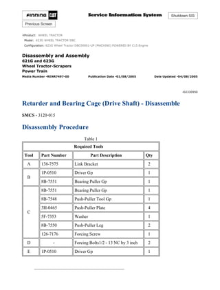
- 1. Shutdown SIS Previous Screen Product: WHEEL TRACTOR Model: 623G WHEEL TRACTOR DBC Configuration: 623G Wheel Tractor DBC00001-UP (MACHINE) POWERED BY C15 Engine Disassembly and Assembly 621G and 623G Wheel Tractor-Scrapers Power Train Media Number -RENR7497-00 Publication Date -01/08/2005 Date Updated -04/08/2005 i02330950 Retarder and Bearing Cage (Drive Shaft) - Disassemble SMCS - 3120-015 Disassembly Procedure Table 1 Required Tools Tool Part Number Part Description Qty A 138-7575 Link Bracket 2 B 1P-0510 Driver Gp 1 8B-7551 Bearing Puller Gp 1 C 8B-7551 Bearing Puller Gp 1 8B-7548 Push-Puller Tool Gp 1 3H-0465 Push-Puller Plate 4 5F-7353 Washer 1 8B-7550 Push-Puller Leg 2 126-7176 Forcing Screw 1 D - Forcing Bolts1/2 - 13 NC by 3 inch 2 E 1P-0510 Driver Gp 1 1/7(W) w 2021/4/10 https://127.0.0.1/sisweb/sisweb/techdoc/techdoc_print_page.jsp?returnurl=/sisweb/sisw...
- 2. Illustration 1 g01049519 1. Remove bolts (3) and retainer (4). Remove bolts (2) from stator (1) . Illustration 2 g01049520 2. Install Tooling (A) and a suitable lifting device to stator (1). Remove stator (1) from housing (5). The weight of stator (1) is approximately 23 kg (50 lb). Illustration 3 g01049526 2/7(W) w 2021/4/10 https://127.0.0.1/sisweb/sisweb/techdoc/techdoc_print_page.jsp?returnurl=/sisweb/sisw...
- 3. 3. Remove bolts (6) and spider (7) . Illustration 4 g01049534 Illustration 5 g01049535 4. Remove deflector (10) from spider (7). Use Tooling (B) and a suitable press to remove bearing (9). Remove retainer (8) . 3/7(W) w 2021/4/10 https://127.0.0.1/sisweb/sisweb/techdoc/techdoc_print_page.jsp?returnurl=/sisweb/sisw...
- 4. Illustration 6 g01049538 5. Install Tooling (A) and a suitable lifting device to rotor (12). Remove rotor (12) and shaft (11) from housing (5) . Illustration 7 g01049539 6. Remove rings (13) and rings (14) from both sides of the rotor. Illustration 8 g01049541 7. Use Tooling (C) to remove carriers (15) from both sides of rotor (12) . 4/7(W) w 2021/4/10 https://127.0.0.1/sisweb/sisweb/techdoc/techdoc_print_page.jsp?returnurl=/sisweb/sisw...
- 5. Illustration 9 g01049542 8. Remove gear (16) from shaft (11) . Illustration 10 g01049543 9. Remove bolts (17) . Illustration 11 g01049544 10. Use Tooling (D) in order to remove cover (18) from housing (5) . 5/7(W) w 2021/4/10 https://127.0.0.1/sisweb/sisweb/techdoc/techdoc_print_page.jsp?returnurl=/sisweb/sisw...
- 6. Illustration 12 g01049546 11. Remove nut (19), retainer (20), and gear (21) . Illustration 13 g01049547 Illustration 14 g01049548 12. Remove O-ring seal (22), washer (23), washer (25), and shaft (26) from gear (21) . 6/7(W) w 2021/4/10 https://127.0.0.1/sisweb/sisweb/techdoc/techdoc_print_page.jsp?returnurl=/sisweb/sisw...
- 7. 13. Use Tooling (E) and a suitable press to remove bearing (24) from gear (21) . Illustration 15 g01049549 14. Remove O-ring seal (27), bearing (28), and seal (29) from cover (18) . Illustration 16 g01049550 15. Remove plugs (30), (31), and (32) from housing (5) . Copyright 1993 - 2021 Caterpillar Inc. All Rights Reserved. Private Network For SIS Licensees. Sat Apr 10 18:44:37 UTC+0800 2021 7/7(W) w 2021/4/10 https://127.0.0.1/sisweb/sisweb/techdoc/techdoc_print_page.jsp?returnurl=/sisweb/sisw...
- 8. Shutdown SIS Previous Screen Product: WHEEL TRACTOR Model: 623G WHEEL TRACTOR DBC Configuration: 623G Wheel Tractor DBC00001-UP (MACHINE) POWERED BY C15 Engine Disassembly and Assembly 621G and 623G Wheel Tractor-Scrapers Power Train Media Number -RENR7497-00 Publication Date -01/08/2005 Date Updated -04/08/2005 i02042129 Retarder and Bearing Cage (Drive Shaft) - Assemble SMCS - 3120-016 Assembly Procedure Table 1 Required Tools Tool Part Number Part Description Qty A 138-7575 Link Bracket 2 E 1P-0510 Driver Gp 1 Illustration 1 g01049550 1. Install plugs (30), (31), and (32) into housing (5) . 1/6(W) w 2021/4/10 https://127.0.0.1/sisweb/sisweb/techdoc/techdoc_print_page.jsp?returnurl=/sisweb/sisw...
- 9. Illustration 2 g01049549 2. Install seal (29) and bearing (28) into cover (18). Install O-ring seal (27) onto cover (18) . Illustration 3 g01049547 2/6(W) w 2021/4/10 https://127.0.0.1/sisweb/sisweb/techdoc/techdoc_print_page.jsp?returnurl=/sisweb/sisw...
- 10. Illustration 4 g01049548 3. Use Tooling (E) and a suitable press to install bearing (24) into gear (21) . 4. Install washer (25), shaft (26), washer (23), and O-ring seal (22) into gear (21) . Illustration 5 g01049546 5. Install gear (21), retainer (20), and nut (19) . Illustration 6 g01049663 3/6(W) w 2021/4/10 https://127.0.0.1/sisweb/sisweb/techdoc/techdoc_print_page.jsp?returnurl=/sisweb/sisw...
- 11. 6. Install cover (18) and bolts (17) onto housing (5) . Illustration 7 g01049542 7. Install gear (16) onto shaft (11) . Illustration 8 g01049666 8. Install carriers (15) (not shown) onto both sides of rotor (12). Install rings (13) and rings (14) onto both sides of rotor (12) . 4/6(W) w 2021/4/10 https://127.0.0.1/sisweb/sisweb/techdoc/techdoc_print_page.jsp?returnurl=/sisweb/sisw...
- 12. Illustration 9 g01049538 9. Install shaft (11) into housing (5) . 10. Install Tooling (A) and a suitable lifting device to rotor (12). Install rotor (12) onto housing (5) . Illustration 10 g01049535 11. Install retainer (8) onto spider (7). Use Tooling (E) and a suitable press to install bearing (9). Install deflector (10) onto spider (7) . 5/6(W) w 2021/4/10 https://127.0.0.1/sisweb/sisweb/techdoc/techdoc_print_page.jsp?returnurl=/sisweb/sisw...
- 13. Illustration 11 g01049526 12. Install spider (7) and bolts (6) . Illustration 12 g01049520 13. Install Tooling (A) and a suitable lifting device to stator (1). Install stator (1) onto housing (5). The weight of stator (1) is approximately 23 kg (50 lb). Illustration 13 g01049519 14. Install bolts (2) into stator (1). Tighten bolts (2) to a torque of 50 ± 7 N·m (37 ± 5 lb ft). Install retainer (4) and bolts (3) . Copyright 1993 - 2021 Caterpillar Inc. All Rights Reserved. Private Network For SIS Licensees. Sat Apr 10 18:45:32 UTC+0800 2021 6/6(W) w 2021/4/10 https://127.0.0.1/sisweb/sisweb/techdoc/techdoc_print_page.jsp?returnurl=/sisweb/sisw...
- 14. Shutdown SIS Previous Screen Product: WHEEL TRACTOR Model: 623G WHEEL TRACTOR DBC Configuration: 623G Wheel Tractor DBC00001-UP (MACHINE) POWERED BY C15 Engine Disassembly and Assembly 621G and 623G Wheel Tractor-Scrapers Power Train Media Number -RENR7497-00 Publication Date -01/08/2005 Date Updated -04/08/2005 i02042131 Retarder and Bearing Cage (Drive Shaft) - Install SMCS - 3120-012 Installation Procedure Table 1 Required Tools Tool Part Number Part Description Qty A 2D-1201 Eyebolt 1 B 140-7742 Sleeve 1 NOTICE Keep all parts clean from contaminants. Contamination of the hydraulic system with foreign material will reduce the service life of the hydraulic system components. To prevent contaminants from entering the hydraulic system, always plug or cap the lines, fittings, or hoses as they are disconnected. Cover any disassembled components and clean them properly before assembly. Clean the hydraulic system properly after any major component exchange or especially after a component failure, to remove any contamination. 1/3(W) w 2021/4/10 https://127.0.0.1/sisweb/sisweb/techdoc/techdoc_print_page.jsp?returnurl=/sisweb/sisw...
- 15. 1. Clean all parts and inspect all parts. If any parts are worn or damaged, use new parts for replacement. Illustration 1 g01049725 Illustration 2 g01049810 2. Install Tooling (A) into retarder (2). Use Tooling (B) in order to protect the lifting strap from other components of the machine. The weight of retarder (2) is approximately 109 kg (240 lb). 3. Position retarder (2) and install bolts (7) . 4. Connect hose assembly (3) . 2/3(W) w 2021/4/10 https://127.0.0.1/sisweb/sisweb/techdoc/techdoc_print_page.jsp?returnurl=/sisweb/sisw...
- 16. Illustration 3 g01049726 5. Install tube assembly (4). Install hose (6) and tighten clamps (5) . Illustration 4 g01049724 6. Connect hose assembly (1) . End By: a. Install the retarder hydraulic control valve. Refer to Disassembly and Assembly, "Retarder Hydraulic Control Valve - Install". b. Install the flywheel scavenge pump. Refer to Disassembly and Assembly, "Flywheel Scavenge Pump - Install". c. Install the drive shaft. Refer to Disassembly and Assembly, "Drive Shaft - Remove and Install". d. Install the secondary steering pump. Refer to Disassembly and Assembly, "Secondary Steering Pump - Install". Copyright 1993 - 2021 Caterpillar Inc. All Rights Reserved. Private Network For SIS Licensees. Sat Apr 10 18:46:28 UTC+0800 2021 3/3(W) w 2021/4/10 https://127.0.0.1/sisweb/sisweb/techdoc/techdoc_print_page.jsp?returnurl=/sisweb/sisw...
- 17. Shutdown SIS Previous Screen Product: WHEEL TRACTOR Model: 623G WHEEL TRACTOR DBC Configuration: 623G Wheel Tractor DBC00001-UP (MACHINE) POWERED BY C15 Engine Disassembly and Assembly 621G and 623G Wheel Tractor-Scrapers Power Train Media Number -RENR7497-00 Publication Date -01/08/2005 Date Updated -04/08/2005 i02301147 Bearing Cage (Drive Shaft) - Remove SMCS - 3267-011 Removal Procedure Table 1 Required Tools Tool Part Number Part Description Qty A 2D-1201 Eyebolt 1 B 140-7742 Sleeve 1 C Forcing Bolt7/16 - 14 NC by 3.5 inch 2 ZZ 6V-9832 Cap As 2 6V-9511 Plug 2 Start By: A. Remove the secondary steering pump. Refer to Disassembly and Assembly, "Secondary Steering Pump - Remove". B. Remove the drive shaft. Refer to Disassembly and Assembly, "Drive Shaft - Remove and Install". C. Remove the flywheel scavenge pump. Refer to Disassembly and Assembly, "Flywheel Scavenge Pump - Remove". Note: SERVICE DATA: TOOLING (ZZ) WILL NOT BE IDENTIFIED IN PHOTOGRAPHS IN THE REMOVAL OR THE INSTALLATION. THIS TOOLING IS SHOWN IN ORDER TO ASSIST THE EXPERIENCED SERVICEMAN. 1/4(W) w 2021/4/10 https://127.0.0.1/sisweb/sisweb/techdoc/techdoc_print_page.jsp?returnurl=/sisweb/sisw...
- 18. At operating temperature, the hydraulic oil is hot and under pressure. Hot oils can cause burns. To prevent possible personal injury, release the pressure in the work tool hydraulic circuit (boom, stick, bucket, and swing), travel circuits, and the hydraulic oil tank at the filler cap before any hydraulic lines or components are disconnected or removed. Remove the filler cap only when the engine is stopped and the filler cap is cool enough to touch. NOTICE Keep all parts clean from contaminants. Contamination of the hydraulic system with foreign material will reduce the service life of the hydraulic system components. To prevent contaminants from entering the hydraulic system, always plug or cap the lines, fittings, or hoses as they are disconnected. Cover any disassembled components and clean them properly before assembly. Clean the hydraulic system properly after any major component exchange or especially after a component failure, to remove any contamination. NOTICE Care must be taken to ensure that fluids are contained during performance of inspection, maintenance, testing, adjusting and repair of the product. Be prepared to collect the fluid with suitable containers before opening any compartment or disassembling any component containing fluids. Refer to Special Publication, NENG2500, "Caterpillar Tools and Shop Products Guide" for tools and supplies suitable to collect and contain fluids on Caterpillar products. Dispose of all fluids according to local regulations and mandates. 2/4(W) w 2021/4/10 https://127.0.0.1/sisweb/sisweb/techdoc/techdoc_print_page.jsp?returnurl=/sisweb/sisw...
- 19. Illustration 1 g01050146 1. Disconnect hose assembly (1) . Illustration 2 g01050143 2. Install Tooling (A) into retarder housing (2). Use Tooling (B) in order to protect the lifting strap from other components of the machine. The weight of retarder housing (2) is approximately 109 kg (240 lb). 3. Disconnect hose assembly (3) . 3/4(W) w 2021/4/10 https://127.0.0.1/sisweb/sisweb/techdoc/techdoc_print_page.jsp?returnurl=/sisweb/sisw...
- 20. Illustration 3 g01050144 4. Loosen clamps (5) and remove hose (6). Remove tube assembly (4). Use a suitable container to catch fluid leakage. Illustration 4 g01050145 5. Remove bolts (7). Use Tooling (C) and remove retarder housing (2). The weight of retarder housing (2) is approximately 109 kg (240 lb). Copyright 1993 - 2021 Caterpillar Inc. All Rights Reserved. Private Network For SIS Licensees. Sat Apr 10 18:47:24 UTC+0800 2021 4/4(W) w 2021/4/10 https://127.0.0.1/sisweb/sisweb/techdoc/techdoc_print_page.jsp?returnurl=/sisweb/sisw...
- 21. Shutdown SIS Previous Screen Product: WHEEL TRACTOR Model: 623G WHEEL TRACTOR DBC Configuration: 623G Wheel Tractor DBC00001-UP (MACHINE) POWERED BY C15 Engine Disassembly and Assembly 621G and 623G Wheel Tractor-Scrapers Power Train Media Number -RENR7497-00 Publication Date -01/08/2005 Date Updated -04/08/2005 i02301148 Bearing Cage (Drive Shaft) - Disassemble SMCS - 3267-015 Disassembly Procedure Table 1 Required Tools Tool Part Number Part Description Qty A Forcing Bolts1/2 - 13 NC by 3 inch 2 B 1P-0520 Driver Gp 1 C 1P-0510 Driver Gp 1 D 8B-7551 Bearing Puller Gp 1 Start By: A. Remove the bearing cage. Refer to Disassembly and Assembly, "Bearing Cage (Drive Shaft) - Remove". 1/6(W) w 2021/4/10 https://127.0.0.1/sisweb/sisweb/techdoc/techdoc_print_page.jsp?returnurl=/sisweb/sisw...
- 22. Illustration 1 g01049201 1. Remove bolts (1) and retainer (2) . 2/6(W) w 2021/4/10 https://127.0.0.1/sisweb/sisweb/techdoc/techdoc_print_page.jsp?returnurl=/sisweb/sisw...
- 23. Illustration 2 g01049202 2. Remove bolts (3). Use Tooling (A) in order to remove cover (4) . 3/6(W) w 2021/4/10 https://127.0.0.1/sisweb/sisweb/techdoc/techdoc_print_page.jsp?returnurl=/sisweb/sisw...
- 24. Illustration 3 g01049203 3. Remove spacer (9), gear (8), bearing (7), and shaft (6) from cover (4). Use Tooling (B) to remove seal (5) . 4. Remove nut (10), retainer (11), bolt (17), seal (16), thrust washer (15), gear (14), and bearing (13). Use Tooling (C) to remove thrust washer (12) . 4/6(W) w 2021/4/10 https://127.0.0.1/sisweb/sisweb/techdoc/techdoc_print_page.jsp?returnurl=/sisweb/sisw...
- 25. Illustration 4 g01049204 5. Remove bolts (20), spider (19), and deflector (18) . Illustration 5 g01049206 6. Use Tooling (C), Tooling (D), and a suitable press to remove bearing (21) and retainer (22) from spider (19) . Copyright 1993 - 2021 Caterpillar Inc. All Rights Reserved. Sat Apr 10 18:48:19 UTC+0800 2021 5/6(W) w 2021/4/10 https://127.0.0.1/sisweb/sisweb/techdoc/techdoc_print_page.jsp?returnurl=/sisweb/sisw...
- 26. Private Network For SIS Licensees. 6/6(W) w 2021/4/10 https://127.0.0.1/sisweb/sisweb/techdoc/techdoc_print_page.jsp?returnurl=/sisweb/sisw...
- 27. Shutdown SIS Previous Screen Product: WHEEL TRACTOR Model: 623G WHEEL TRACTOR DBC Configuration: 623G Wheel Tractor DBC00001-UP (MACHINE) POWERED BY C15 Engine Disassembly and Assembly 621G and 623G Wheel Tractor-Scrapers Power Train Media Number -RENR7497-00 Publication Date -01/08/2005 Date Updated -04/08/2005 i02040714 Bearing Cage (Drive Shaft) - Assemble SMCS - 3267-016 Assembly Procedure Table 1 Required Tools Tool Part Number Part Description Qty B 1P-0520 Driver Gp 1 1/5(W) w 2021/4/10 https://127.0.0.1/sisweb/sisweb/techdoc/techdoc_print_page.jsp?returnurl=/sisweb/sisw...
- 28. Illustration 1 g01049301 1. Install retainer (22) onto spider (19). Raise the temperature of bearing (21). Install bearing (21) onto spider (19) . Illustration 2 g01049204 2. Install deflector (18), spider (19), and bolts (20) . 2/5(W) w 2021/4/10 https://127.0.0.1/sisweb/sisweb/techdoc/techdoc_print_page.jsp?returnurl=/sisweb/sisw...
- 29. Illustration 3 g01049203 3. Install thrust washer (12), bearing (13), gear (14), thrust washer (15), seal (16), bolt (17), retainer (11), and nut (10) onto cover (4) . 4. Use Tooling (B) to install seal (5). Install shaft (6), bearing (7), gear (8), and spacer (9) onto cover (4) . 3/5(W) w 2021/4/10 https://127.0.0.1/sisweb/sisweb/techdoc/techdoc_print_page.jsp?returnurl=/sisweb/sisw...
- 30. Please write to us. Our email: aservicemanualpdf@yahoo.com Please go to the homepage to get the full manual, or other brand PDF manuals. Home Site: aservicemanualpdf.com
- 31. Thank you very much for your reading. Please Click Here. Then Get COMPLETE MANUAL. NO WAITING NOTE: If there is no response to click on the link above, please download the PDF document first and then click on it. GET MORE OTHER MANUALS https://www.aservicemanualpdf.com/ GET MORE OTHER MANUALS https://www.aservicemanualpdf.com/
- 32. Illustration 4 g01049202 5. Install cover (4) and bolts (3) . 4/5(W) w 2021/4/10 https://127.0.0.1/sisweb/sisweb/techdoc/techdoc_print_page.jsp?returnurl=/sisweb/sisw...
- 33. Illustration 5 g01049201 6. Install retainer (2) and bolts (1) . End By: Install the bearing cage. Refer to Disassembly and Assembly, "Bearing Cage (Drive Shaft) - Install". Copyright 1993 - 2021 Caterpillar Inc. All Rights Reserved. Private Network For SIS Licensees. Sat Apr 10 18:49:15 UTC+0800 2021 5/5(W) w 2021/4/10 https://127.0.0.1/sisweb/sisweb/techdoc/techdoc_print_page.jsp?returnurl=/sisweb/sisw...
- 34. Shutdown SIS Previous Screen Product: WHEEL TRACTOR Model: 623G WHEEL TRACTOR DBC Configuration: 623G Wheel Tractor DBC00001-UP (MACHINE) POWERED BY C15 Engine Disassembly and Assembly 621G and 623G Wheel Tractor-Scrapers Power Train Media Number -RENR7497-00 Publication Date -01/08/2005 Date Updated -04/08/2005 i02044770 Bearing Cage (Drive Shaft) - Install SMCS - 3267-012 Installation Procedure Table 1 Required Tools Tool Part Number Part Description Qty A 2D-1201 Eyebolt 1 B 140-7742 Sleeve 1 NOTICE Keep all parts clean from contaminants. Contamination of the hydraulic system with foreign material will reduce the service life of the hydraulic system components. To prevent contaminants from entering the hydraulic system, always plug or cap the lines, fittings, or hoses as they are disconnected. Cover any disassembled components and clean them properly before assembly. Clean the hydraulic system properly after any major component exchange or especially after a component failure, to remove any contamination. 1/3(W) w 2021/4/10 https://127.0.0.1/sisweb/sisweb/techdoc/techdoc_print_page.jsp?returnurl=/sisweb/sisw...