
Recommended
Recommended
More Related Content
What's hot
What's hot (19)
Viewers also liked
Similar to G04102032035
Similar to G04102032035 (20)
G04102032035
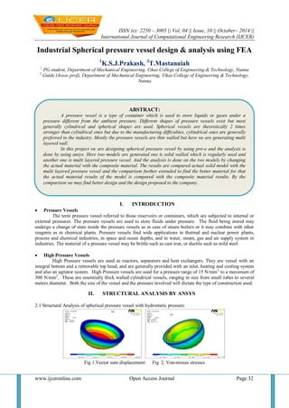
- 1. ISSN (e): 2250 – 3005 || Vol, 04 || Issue, 10 || October– 2014 || International Journal of Computational Engineering Research (IJCER) www.ijceronline.com Open Access Journal Page 32 Industrial Spherical pressure vessel design & analysis using FEA 1K.S.J.Prakash, 2T.Mastanaiah 1 PG student, Department of Mechanical Engineering, Vikas College of Engineering & Technology, Nunna 2 Guide (Assoc.prof), Department of Mechanical Engineering, Vikas College of Engineering & Technology, Nunna I. INTRODUCTION Pressure Vessels The term pressure vessel referred to those reservoirs or containers, which are subjected to internal or external pressures. The pressure vessels are used to store fluids under pressure. The fluid being stored may undergo a change of state inside the pressure vessels as in case of steam boilers or it may combine with other reagents as in chemical plants. Pressure vessels find wide applications in thermal and nuclear power plants, process and chemical industries, in space and ocean depths, and in water, steam, gas and air supply system in industries. The material of a pressure vessel may be brittle such as cast iron, or ductile such as mild steel. High Pressure Vessels High Pressure vessels are used as reactors, separators and heat exchangers. They are vessel with an integral bottom and a removable top head, and are generally provided with an inlet, heating and cooling system and also an agitator system. High Pressure vessels are used for a pressure range of 15 N/mm2 to a maximum of 300 N/mm2. These are essentially thick walled cylindrical vessels, ranging in size from small tubes to several meters diameter. Both the size of the vessel and the pressure involved will dictate the type of construction used. II. STRUCTURAL ANALYSIS BY ANSYS 2.1 Structural Analysis of spherical pressure vessel with hydrostatic pressure. Fig 1.Vector sum displacement Fig 2. Von-misses stresses ABSTRACT: A pressure vessel is a type of container which is used to store liquids or gases under a pressure different from the ambient pressure. Different shapes of pressure vessels exist but most generally cylindrical and spherical shapes are used. Spherical vessels are theoretically 2 times stronger than cylindrical ones but due to the manufacturing difficulties, cylindrical ones are generally preferred in the industry. Mostly the pressure vessels are thin walled but here we are generating multi layered wall. In this project we are designing spherical pressure vessel by using pro-e and the analysis is done by using ansys. Here two models are generated one is solid walled which is regularly used and another one is multi layered pressure vessel. And the analysis is done on the two models by changing the actual material with the composite material. The results are compared actual solid model with the multi layered pressure vessel and the comparison further extended to find the better material for that the actual material results of the model is compared with the composite material results. By the comparison we may find better design and the design proposed to the company.
- 2. Industrial Spherical pressure vessel design & analysis using FEA www.ijceronline.com Open Access Journal Page 33 2.2 Structural Analysis of spherical pressure vessel with burst pressure Fig 3.Vector sum displacement Fig 4. Von-misses stresses 2.3 Structural Analysis of dished end of the multi layer pressure vessel with hydrostatic pressure 27.3 N/mm2 Fig 5.Vector sum displacement Fig 6. Von-misses stresses 2.4 Structural Analysis of dished end of the multi layer pressure vessel with burst pressure 64.52 N/mm2 Fig 7.Vector sum displacement Fig 8.Von-misses stresses 2.5 Structural Analysis of dished end of the multi layer pressure vessel with hydrostatic pressure 27.3 N/mm2 Fig9.Vector sum displacement Fig 10.Von-misses stresses
- 3. Industrial Spherical pressure vessel design & analysis using FEA www.ijceronline.com Open Access Journal Page 34 2.6 Structural Analysis of dished end of the multi layer pressure vessel with burst pressure 64.52 N/mm2 Fig 11.Vector sum displacement Fig 12.Von-misses stresses III. RESULTS & DISCUSSION 3.1 Structural Analysis of dished end of the mono layer pressure vessel with hydrostatic pressure 27.3 N/mm2 Stresses & Deformation Minimum ( N/mm2) Maximum ( N/mm2) Von Mises Stresses 5.825 147.778 Vector sum deformation 0.0000 0.46268 Table 1.Results at pressure of 27.3 N/mm2 3.2 Structural Analysis of burst pressure in dished end of the mono layer pressure vessel with burst pressure 85.37 N/mm2 Stresses & Deformation Minimum (mm) Maximum (mm) Vector sum deformation 0.0000 1.447 Von Mises Stresses 18.216 462.118 Table 2.Results at pressure of 85.37 N/mm2 3.3 Structural Analysis of dished end of the multi - layer pressure vessel with hydrostatic pressure 27.3 N/mm2 Stresses & Deformation Minimum (mm) Maximum (mm) Vector sum deformation 0.0000 0.536567 Von Mises Stresses 11.871 133.147 Table 3.Results at pressure of 27.3 N/mm2 3.4 Structural Analysis of burst pressure in dished end of the multi - layer pressure vessel with burst pressure 64.52 N/mm2 Stresses & Deformation Minimum (mm) Maximum (mm) Vector sum deformation 0.0000 1.268 Von Mises Stresses 28.056 314.676 Table 4.Results at pressure of 64.52 N/mm2 3.5 Structural Analysis of dished end of the multi - layer pressure vessel with hydrostatic pressure 27.3 N/mm2 Deformation Minimum (mm) Maximum (mm) Vector sum deformation 0.0000 1.984 Von Mises Stresses 46.031 386.136 Table 5.Results at pressure of 27.3 N/mm2 3.6 Structural Analysis of burst pressure in dished end of the multi - layer pressure vessel with burst pressure 64.52 N/mm2 Deformation Minimum (mm) Maximum (mm) Vector sum deformation 0.0000 4.689 Von Mises Stresses 108.787 912.582 Table 6.Results at pressure of 64.52 N/mm2
- 4. Industrial Spherical pressure vessel design & analysis using FEA www.ijceronline.com Open Access Journal Page 35 IV. CONCLUSIONS AND FUTURE SCOPE 4.1 Conclusions 1. At present multilayered vessels are being used extensively in many industries when compare to solid wall pressure vessels. Because, there is a huge difference in weight of the vessel and uniform stress distribution among the vessel wall thickness. 2. There is a percentage saving in material of 28.48% by using multilayered vessels in the place of solid walled vessel when both the vessels are manufactured with same material i.e. SA515 Grade 70 steel . 3. There is a percentage saving in material of 91.62% by using multilayered CFRP material vessels when compared to multilayered SA515 Grade 70 steel material vessels. 4. This decreases not only the overall weight of the component but also the cost of the material required to manufacture the pressure vessel. This is one of the main aspects of designer to keep the weight and cost as low as possible. 5. The Stress variation from inner side to outer side of the multilayered pressure vessel is around 11.76%, where as to that of solid wall vessel is 17.32%. This means that the stress distribution is uniform when compared to that of solid wall vessel. 6. Minimization of stress concentration is another most important aspect of the designer. It also shows that the material is utilized most effectively in the fabrication of shell. 7. Owing to the advantages of the multi layered pressure vessels over the conventional single walls pressure vessels, it is concluded that multi layered pressure vessels are superior for high pressures and high temperature operating conditions. 8. The burst pressures for various fiber orientations are predicted using the Tsai-Wu failure criteria. The ± 25° fiber orientation angle is obtained as the optimum fiber orientation angle for the composite pressure vessel subjected to high internal pressure loading. 4.2 Future Scope 1. Analysis on different layer materials to reduce cost of production 2. Optimization of shell thickness for the given conditions. REFERENCES [1]. BHPV manual on Multilayer Pressure Vessels. [2]. ASME Code Book Section VIII & Division I. [3]. International Journal of Engineering Trends and Technology- Volume3 Issue5- 2012, ISSN: 2231-5381. [4]. R.S.Khurmi and J.K.Gupta., “A Test Book of Machine Design” S.Chand publications. [5]. Brownell and Young, “Process Equipment Design” Seely, F.B., and Smith, [6]. John F.Henvey “ Pressure Vessel Design -Nuclear and Chemical Applications” An East-west Edition, Newyork [7]. Henry H.Bednar “ Pressure Vessel Code Book” [8]. Fratcher, G.E : New alloys for Multilayer Vessels” Vol. 33 [9]. Harold.H.Wait e, “Pressure Vessel and Piping Design Analysis” [10]. Mc Cabe, J.S and Rothrock, E.W., “Multilayer Vessels for High Pressure,” ASME Mechanical Engineering PP 34-39. [11]. Mc Cabe, J.S and Rothrock, E.W., “ Recent Developments in Multilayer Vessels,” British chemical engineering Vol.16, No6,1971 [12]. Noel, M.R., “Multiwall Pressure Vessels,” British chemical Engineering Vol.15, No7, 1970. [13]. O.C.Zienkeewz.”The Finite Element Method in Structural and Continuum Mechanics. [14]. Ansys User’s Manual, Swanson Anlysis Systems, Inc.1995. [15]. E.N. Buarque, J.R.M.Almeida, “The effect of cylindrical defects on the tensile strength of glass fiber/vinyl-ester matrix reinforced composite pipes”, Composite Structures, Vol. 79, pp. 270–279, 2007. [16]. J.M. Duell, J.M. Wilson, M.R. Kessler, “Analysis of a carbon composite overwrap pipeline repair system”, International Journal of Pressure Vessels and Piping, Vol. 85, pp. 782–788, 2008. [17]. R.R. Chang, “Experimental and theoretical analyses of first-ply failure of laminated composite pressure vessels”, Composite Structures, Vol. 49, pp. 237-243, 2000 [18]. L. Parnas, N. Katırcı, “Design of fiber-reinforced composite pressure vessels under various loading conditions”, Composite Structures, Vol. 58, pp. 83-95, 2002. [19]. M.A. Wahab, M.S. Alam, S.S. Pang, J.A. Peck, R.A. Jones, “Stress analysis of non-conventional composite pipes”, Composite Structures,Vol. 79, pp. 125–132, 2007. [20]. R.M. Guedes, “Stress–strain analysis of a cylindrical pipe subjected to a transverse load and large deflections”, Composite Structures, Vol.88, pp. 188–194, 2009. [21]. H. Bakaiyan, H. Hosseini, E. Ameri, “Analysis of multi-layered filament-wound composite pipes under combined internal pressure and thermo mechanical loading with thermal variations”, Composite Structures, Vol. 88, pp. 532–541, 2008. [22]. F. Ratter, D. Lueddeke, S.C. Huang, “Finite Element Analysis of the Lateral Crushing Behaviour of Segmented Composite Tubes”, Journal of Engineering Technology and Education, Vol. 6, No.1, , pp. 1-16, 2009. [23]. DOT CCFC standards. [24]. Nagesh, “Finite-element Analysis of Composite Pressure Vessels with Progressive Degradation”, Defence Science Journal, Vol. 53, No. 1, pp. 75-86, 2003.