2. INDUCTION MOTORS
1.0 COMMON STANDARDS
1.1 Great Britain : BS 4999 1987
: BS 5000 Part 16 1988
1.2 Germany : VDE 0530
1.3 France : NF C51-111/11.1975
1.4 IEC : IEC 34, IEC 72
1.5 NEMA : MG1 Part 4, MG1-1.26B
2.0 PROTECTION CLASS
Designation 1st Numeral 2nd Numeral
Protection against contact and against Protection against water
ingress of foreign bodies
IP44 Protection against contact with live or Water splashed against the
moving parts inside the motor enclosure any direction shall have no
by tools, wires or such objects of
thickness greater than 1mm
(exclude the ventilating openings
of cooling fan)
IP54 Complete protection against contact Water splashed against the
with live or moving parts inside the any direction shall have no
motor
IP55 Protection against harmful deposit of Water projected by a nozzle
dust. The ingress of dust is not totally motor from any direction sh
prevented but dust cannot enter in an harmful effect
amount sufficient to interfere with
satisfactory operation of the motor
IP56 Protection against harmful deposit of A flood with a wave or a str
dust. The ingress of dust is not totally water should not penetrate
prevented but dust cannot enter in an of the motor in an amount c
amount sufficient to interfere with results
satisfactory operation of the motor
3.0) INSULATION CLASS
CLASS OF INSULATION
A B F
MAXIMUM DESIGN TEMPERATURE 105 130 155
LIMITING OPERATING TEMPERATURE 100 120 145
3. LIMITING AMBIENT TEMPARATURE 40 40 40
MAXIMUM TEMPERATURE RISE 60 80 105
4.0 DUTY CYCLES
Designation Duty Type Explanation
S1 Continuous Duty Operation at constant load of sufficie
equilibrium to be reached
S2 Short Time Duration Operation at constant load during a g
that required to reach thermal equilib
and de-energised period of sufficient
machine temperature within 2
S3 Intermittent Periodic Duty A sequence of identical duty cycles,
without influence of running of operation at constant load and a re
up period period. In this duty the cycle is such t
does not significantly affect the temp
S4 Intermittent Periodic Duty As S3, but with each cycle, including
with influence of running up of starting
period
S5 Intermittent Periodic Duty As S4, but with each cycle, including
with influence of running up electric braking
period and electrical braking
S6 Continuous Operation Periodic A sequence of identical duty cycles,
Duty of a period of operation at constant lo
operation at no load.There is no rest
S7 Continuous Operation Periodic As S6, with each cycle, including a p
Duty with starting and electrical a period of electric braking
braking
S8 Continuous Operation Periodic Continuous operation with load and s
Duty with relative load speed include electric braking
changes
S9 Duty With No Periodic Load A series of non identical load cycles
and Speed Variations and braking
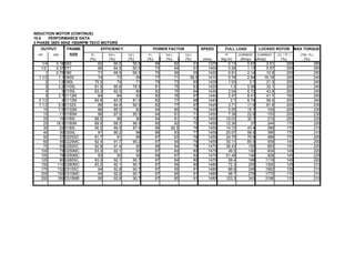
5.0 OUTPUT POWER CORRECTIONS
Ambient Temperatures (oC) 30 40 45
4. Rated Ouput Reduced To (%) 100 100 96
Altitude of Site (m) 1000 1050 2000 2500
Rated Ouput Reduced To (%) 100 97 94 90
6.0 VOLTAGE
Standard Voltages = 220, 380 and 415 Volts
Voltage Tolerance = ± 5%
Sustained operation on voltages exceeding ± 5% rated voltage will result in overheating
7.0 TYPES OF MOUNTING
a) Horizontal Foot Mounted
b) Vertical Flange Mounted
c) Horizontal Foot & Flange Mounted
8.0 BEARINGS
ELECTRIM MOTORS TECO MOTORS
Motors Roller Bearings Motors
Type Pole DE NDE Type
ANTI FRICTION DOUBLE SHIELDED PRE-PACKED WITH ANTI FRICTION DOUBLE
GREASE
63 2, 4, 6, 8 6202 2RS D63D
71 2, 4, 6, 8 6203 2RS D71D
80 2, 4, 6, 8 6204 2RS D80D
90S,L 2, 4, 6, 8 6205 2RS D90SD, LD
100L 2, 4, 6, 8 6206 2RS D100D
112M 2, 4, 6, 8 6306 2RS D112MD
132S,M 2, 4, 6, 8 6203 2RS D132SD, MD
160M,L 2, 4, 6, 8 6309 2ZC3 D160SD,MD
180M,L 2, 4, 6, 8 6311 2ZC3 D180SD,MD
STRV
WITH GREASE NIPPLES AND GREASE RELIEF WITH GREASE NIPP
VALVES DE NDE
200 2 6212 C3 6312 C3 D200LD
200 4, 6, 8 6212 C3 6312 C3 D225SCD
225 2 6213 C3 6313 C3 D225MAD
225 4, 6, 8 6212 C3 6313 C3 D225MCD
250 2 6215 C3 6315 C3
250 4, 6, 8 6212 C3 6315 C3 Note 1 :
280 2 6217 C3 6317 C3
280 4, 6, 8 6217 C3 6317 C3
Type of Grease = Lithium Based Alvania 3
STRV : Strengthened Version
5. 9.0 TERMINAL BOXES
FRAME SIZES TERMINAL BOX POSITION
63 - 180 Top
200 - 280 RH or LH
a) Terminal boxes of frame sizes 63 - 180 can be rotated in steps of 180 Degree
b) Terminal boxes of frame sizes 200 - 280 can be rotated in steps of 90 Degree
10.0 MOTOR HOUSING
The motor housing are made from pressure cast aluminium alloy or cast iron and have intergral fee
Motor feet are detachable from frame size 80-132.
11.0 ROTOR AND SHAFT
a) Rotors are cast from aluminium and are dynamically balance
b) Motor shafts on frame sizes 63 and above have a drilled and tapped hole
in the drive end.
12.0 FANS
a) Motors are surface cooled
b) Fans supplied on frame sized 63-112 are made from plastic
c) Fans supplied on frame sized 132-280 are made from either plastic or aluminium aloy
13.0 OPTIONAL FEATURES
13.1 Over Temperature Protection
a) Manufacturer can fit PTC Thermistors in the stator windings to give temperature protection.
b) The PTC Thermistors need a thermal relay to trip off the motor supply
13.2 Anti-Condensation Heaters (ACH)
a) Anti-Condensation Heaters (ACH) can be fitted on motors which may be subjected to wide variation
in ambient temperature and humidity
b) Heaters are of the tape type applied to the end-windings
14.0 ORDERING
Specify the following information:
a) Make
b) Frame Size
c) Type of Mounting
d) KW Output
e) Rated Speed
f) Rated Voltage
g) Rated Frequency
h) Optional Features
i) Quantity
6. ction against water
r splashed against the motor from
irection shall have no harm effect
r splashed against the motor from
irection shall have no harm effect
r projected by a nozzle against the
r from any direction shall have no
od with a wave or a strong stream
should not penetrate to the inside
e motor in an amount causing destructive
SULATION
H
180
165
7. 40
125
onstant load of sufficient duration for thermal
be reached
onstant load during a given time, less than
o reach thermal equilibrium, followed by a rest
ed period of sufficient duration to re-establish
erature within 2oC of the ambient temperature
identical duty cycles, each including a period
constant load and a rest and de-energised
duty the cycle is such that the starting current
cantly affect the temperature rise.
each cycle, including a significant period
each cycle, including a period of rapid
identical duty cycles, each cycle consisting
peration at constant load and a period of
load.There is no rest or de-energised period
ch cycle, including a period of starting and
ctric braking
eration with load and speed changes which
identical load cycles which includes starting
50
10. 17) AC MOTOR PROBLEMS AND CORRECTIVE ACTIONS
No. Trouble
1 Motor stalls a)
b)
c)
d)
e)
f)
2 Motor connected but does not start a)
b)
c)
d)
e)
f)
g)
3 Motor runs and then dies down a)
b)
c)
4 Motor does not come up to speed a)
b)
11. c)
d)
e)
f)
g)
5 Motor takes too long to accelerate a)
b)
c)
d)
6 Motor runs reverse a)
b)
7 Motor overheats while running under a)
load
b)
c)
d)
e)
f)
g)
h)
12. i)
8 Motor vibrates a)
b)
c)
d)
e)
f)
g)
h)
9 Unbalance line current at 3-phase a)
motor during normal operation
b)
c)
d)
10 Hot bearings a)
b)
c)
d)
e)
11 f)
g)
13. h)
i)
12 Mechanical noise a)
b)
c)
d)
e)
f)
g)
13 Magnetic noise a)
b)
c)
14. RECTIVE ACTIONS
Probable Cause Corrections
Wrong application / selection a) Change type or size. Consult manufacturer
Overlaoded motor b) Reduce load or replace with higher
capacity motor
Low voltage motor c) See the nameplate voltage is restored
Open circuit d) Fuses may be blown. Reset overload relay,
check for open leads
Rotor rubbing e) Replace defective bearings
Incorrect control resistance of wound f) Check control sequence. Replace any
rotor circuits broken resistors. Repair any open circuits.
Check brushes.
One phase open circuit a) Repair lead
Motor may be overlaoded b) Reduce load
Rotor defective c) Look for broken bars or rings.
Replace rotor
Poor stator coil copnnection d) Locate open wire and repair
Blown fused, tripped breaker e) Replace or reset
Rotor rub or frozen bearing(s) f) Replace defective bearings
Starting relay open (single phase) g) Repair or replace relay
Power failure a) Check for loose connections to line, fuses
and to control
Overload b) Reduce load
Rotor rub on increased temperature c) Replace defective bearings
Not applied properly a) Consult supplier for proper type
Voltage too low at motor terminals b) Use higher voltage on transformer terminals
15. because of line drop or increase conductor size
If wound rotor, improper control operation c) Correct secondary control
of secondary resistance
Starting load too high d) Investigate unloading until at full speed or increase motor s
All brushes are riding on rings e) Reseat brushes
(wound rotor)
Broken rotor bars f) Look for cracks near the rings.
Replace if defective
Open primary circuit g) Locate fault and repair
Excessive loading a) Reduce load or increase motor size
Poor circuit b) Check for high resistance connections, repair
Defective squirrel cage rotor c) Replace with new rotor
Applied voltage too low d) Apply correct voltage
Wrong connection or wrong sequence a Reverse any two leads of a 3 phase motor
of phase
Wrong connection (single phase motor) b) Reverse starting winding leads
Check for overload a) Reduce load or increase motor size
Air passages may be clogged with dirt b) Clean all air passages
and prevent proper ventilation at motor
Motor may have one phase open c) Check all leads are well connected
Grounded coil d Locate and repair
Unbalanced terminal voltage e) Check for faulty lead, connections and wiring
Shorted stator coil f) Repair or replace stator
Faulty connection g Check and repair
High or low voltage h) Check terminals of motor with AVO.
Adjust to proper voltage
16. Rotor rubs stator core i) Replace worn bearings
Motor misaligned a) Realign motor with driven equipment
Weak foundations b) Strengthen base
Coupling out of balance c) Balance coupling
Driven equipment unbalance d) Rebalance driven equipment
Defective bearing(s) e Replace bearing(s)
Bearings not in line f) Line up bearings properly
Balancing weights shifted g Rebalance rotor
Polyphase motor running single phase h) Check for open circuit
Unequal terminal volts a) Check leads and connections
Balance applied voltages
Single phase operation b) Check for open contacts or wiring
Poor rotor brush contact to wound rotor c) Renew and reseat brushes
resistance
Shorted turns at stator coils d) Repair or replace stator
Bent or sprung shaft a) Straighten or replace shaft
Ecessive belt pull b) Decrease belt tension
Misalignment c) Correct by realignment of drive
Insufficient lubrication d) Replenish lubricant
Dterioration of grease or lubricant e) Remove old grease, wash bearings
contaminated thoroughly in kerosene, replace with
new grease
Excessive lubricant f) Reduce quantity of grease.
Bearing should not be one-half filled
Heat from hot motor or external source g) Provide shield or extra cooling
17. Overloaded bearing h) Check alignment, side thrust, and end thrust
Broken ball or rough races i) Replace bearing. Also clean housing
thoroughly
Fan rubbing air shield a) Remove interference
Fan striking insulation b) Remove interference
Motor loose on bedplate c) Tighten holding bolts
Failing bearing(s) d) Replace bearing(s)
Excessive vibration e) Rebalance rotor
Rotor rub f) Replace bearings
Loose coupling g) Tighten coupling bolts
Air gap not uniform a) Check and correct bracket fit and bearings
Loose bearings b) Replace bearings
Rotor unbalance c) Rebalance the rotor